Amada IP-500A User manual

Z11OM1203975-03
OPERATION MANUAL
INVERTER WELDING POWER SUPPLY
IP-500A

IP-500A
Contents
1
Thank you for purchasing our Inverter Welding Power Supply IP-500A.
This operation manual describes its method of operation and precautions for use.
Read this operation manual carefully prior to use. Store appropriately for ready reference.
Contents
1. Special Precautions ...................................................................................................... 1-1
(1) Safety Precautions..................................................................................................... 1-1
(2) Precautions for Handling............................................................................................ 1-4
(3) On Disposal ............................................................................................................... 1-5
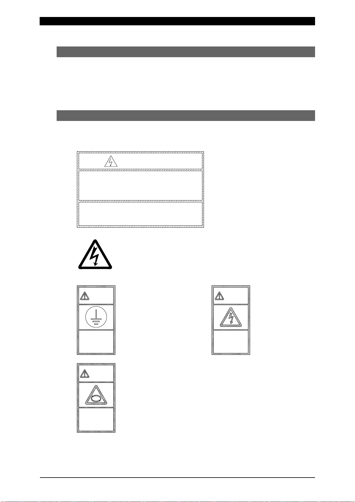
(4) Warning Labels for Safety.......................................................................................... 1-5
2. Features ......................................................................................................................... 2-1
3. Name and Functions of Each Section.......................................................................... 3-1
(1) Front ..........................................................................................................................3-1
(2) Rear...........................................................................................................................3-3
4. How to Operate Screens ............................................................................................... 4-1
(1) STARTING Screen .................................................................................................... 4-1
(2) SCHEDULE Screen ................................................................................................... 4-3
(3) MONITOR Screen...................................................................................................... 4-7
(4) MONITOR SET Screen.............................................................................................. 4-9
(5) MONITOR MODE Screen ........................................................................................ 4-11
(6) MODE SELECT Screen ........................................................................................... 4-14
(7) SETUP Screen ........................................................................................................ 4-20
(8) I/O CHECK Screen .................................................................................................. 4-22
(9) INITIALIZE Screen................................................................................................... 4-23
(10) SCHEDULE COPY Screen .................................................................................... 4-24
(11) ERROR Screen...................................................................................................... 4-26
5. Installation and Connection.......................................................................................... 5-1
(1) Installation Place........................................................................................................ 5-1
(2) Grounding Work......................................................................................................... 5-2
(3) Basic Connection....................................................................................................... 5-2
(4) Connection Procedure ............................................................................................... 5-5
6. Interface ......................................................................................................................... 6-1
(1) Connection Diagram for External Input/Output Signals .............................................. 6-1
(2) Description of External I/O Signals............................................................................. 6-3
(3) Connection of Input Signals ....................................................................................... 6-7
7. Basic Operation............................................................................................................. 7-1
8. Timing Chart .................................................................................................................. 8-1
(1) Basic Sequence......................................................................................................... 8-1
(2) Sequence when the Monitor Judgment is NG ............................................................ 8-3
(3) Occurrence of an Error during Welding Sequence ..................................................... 8-5
(4) Sequence in TRANS SCAN ....................................................................................... 8-6
(5) Sequence when the Monitor Judgment of TRANS SCAN is NG................................. 8-7
9. External Communication Function .............................................................................. 9-1

IP-500A
Contents
2
(1) Introduction ................................................................................................................ 9-1
(2) Data Transmission ..................................................................................................... 9-1
(3) Configuration ............................................................................................................. 9-2
(4) Protocol (Single-Directional Communication) ............................................................. 9-3
(5) Protocol (Bi-Directional Communication).................................................................... 9-6
(6) Data Code Table...................................................................................................... 9-19
10. Specifications .............................................................................................................. 10-1
(1) Specifications........................................................................................................... 10-1
(2) Options (Sold Separately) ........................................................................................ 10-3
(3) Duty Cycle Graph..................................................................................................... 10-4
(4) Schematic................................................................................................................ 10-5
11. Outline Drawing........................................................................................................... 11-1
12. Maintenance................................................................................................................. 12-1
(1) Cleaning and Replacement of Filter ......................................................................... 12-1
13. Troubleshooting .......................................................................................................... 13-1
(1) Fault Code List......................................................................................................... 13-1
14. Schedule Data Table ................................................................................................... 14-1

IP-500A
1. Special Precautions
1-1
These symbols denote
"prohibition". They are
warnings about actions
out of the scope of the
warranty of the product.
These symbols denote
actions which operators
must take.
Each symbol with a
triangle denotes that
the content gives
DANGER, WARNING
or CAUTION to the
operator.
1. Special Precautions
(1) Safety Precautions
Before using, read "Safety Precautions" carefully to understand the correct method
of use.
These precautions are shown for safe use of our products and for prevention of
damage or injury to operators or others. Be sure to read each of them, since all
of them are important for safety.
The meaning of the words and symbols is as follows.
Do not touch the inside of the Power Supply except as instructed.
The interior of this Power Supply carries high voltage. It is very dangerous to
touch any parts except as instructed. When inspecting the interior of the
Power Supply, be sure to turn off the power source of the Power Supply and
wait for at least 5 minutes.
Never disassemble, attempt to repair, or modify the Power Supply.
These actions can cause electric shock and fire.
Consult us or your distributor for inspection and repair.
Never burn, destroy, cut, crush or chemically decompose the Power
Supply.
This product incorporates parts containing gallium arsenide (GaAs).
Denotes operations and practices
that may imminently result in serious
injury or loss of life if not correctly
followed.
Denotes operations and practices
that may result in serious injury or
loss of life if not correctly followed.
WARNING
!
Denotes operations and practices that
may result in personal injury or
damage to the equipment if not
correctl
y
followed.
CAUTION
!
!
DANGER
!
DANGER
!

IP-500A
1. Special Precautions
1-2
Do not insert your fingers or hands between the electrodes.
When welding, keep your fingers and hands away from the electrodes.
Do not touch any welded part or electrode during welding or just after
completion of welding.
The welded parts of a workpiece, electrodes, and the arm are very hot.
Do not touch them; burns may result.
Ground the equipment.
If the Power Supply is not grounded, you may receive an electric shock in
the event of malfunction or current leak. Be sure to perform grounding work.
400 V AC of input voltage: at least class C
!
Connect the specified cables securely.
Cables of insufficient current capacities and loose connections can cause
fire and electric shock.
Do not damage the power cable and connecting cables.
Do not tread on, twist, or apply force to any cable. Doing so may cause the
power cable and connecting cables to become broken, leading to electric
shock and fire.
If any part must be replaced or requires repair, consult us or your distributor.
!
Stop the operation if any trouble occurs.
Continuous operation after occurrence of a trouble such as burning smell,
abnormal sound, abnormal heat, smoke, etc. can cause electric shock and
fire.
If such a trouble occurs, immediately consult us or your distributor.
!
Persons with pacemakers must stay clear of the welding machine.
A person who uses a pacemaker must not approach the welding machine or
walk around the welding site while the welding machine is in operation,
without being permitted by his/her doctor. The welding machine generates a
magnetic field and has effects on the operation of the pacemaker while it is
turned on.
!
Protective gear must be worn.
Put on protective gear such as protective gloves, long-sleeve jacket, leather
apron, etc. Surface flash and expulsion can burn the skin if they touch the
skin.
!
Wear protective glasses.
If you look at the flash directly during welding, your eyes may be damaged.
If any surface flash and expulsion gets in your eye, you may lose your
eyesight.
WARNING
!

IP-500A
1. Special Precautions
1-3
!
Apply the specified supply voltage.
Application of a voltage outside the specified range may result in fire or
electric shock.
Do not allow water to come in contact with the equipment.
Water on the electric parts can cause electric shock and short circuit.
!
Use proper tools (wire strippers, pressure wire connectors, etc.) for
terminal treatment of the connecting cables.
Do not cut the wire conductor; fire or electric shock may result.
!
Install the equipment on a firm and level surface.
Injury may result if the equipment falls or is dropped.
Do not sit on or place objects on the Power Supply.
Failure to observe this precaution may lead to malfunction.
!
Keep combustible matter away from the Power Supply.
Surface flash and expulsion may ignite combustible matter. If it is
impossible to remove all combustible matter, cover it with non-combustible
material.
Do not cover the Power Supply with a blanket, cloth, etc.
Do not cover the Power Supply with a blanket, cloth, etc. while it is in use.
The cover may be overheated and burned.
Do not use this Power Supply for purposes other than welding.
Use of this Power Supply in a manner other than specified can cause
electric shock and fire.
!
Use ear protectors.
Loud noises can damage hearing.
!
Keep a fire extinguisher nearby.
Keep a fire extinguisher in the welding shop in case of fire.
!
Maintain and inspect the Power Supply periodically.
Maintain and inspect the Power Supply periodically, and repair any damage
nearby before starting operation.
CAUTION
!

IP-500A
1. Special Precautions
1-4
(2) Precautions for Handling
When transporting or moving the Power Supply, do not lay it down. Also, handle the
Power Supply with care so as not to make an impact such as drop on it.
Install this Power Supply on a firm and level surface. If it is inclined, malfunction
may result. For ventilation, provide 100 mm clearances to the intake and exhaust
(See 5. (1)).
Do not install the Power Supply in the following locations:
Damp areas (where the humidity is higher than 90%),
areas where temperatures are above 40°C or below 5°C,
areas near a high noise source,
areas where chemicals are handled,
areas where water may condense,
dusty areas,
areas exposed to large amounts of vibration or shock, and
areas at an altitude above 1000 meters.
Clean the exterior of the Power Supply using a soft, dry cloth or one slightly
dampened with water. If the Power Supply is very dirty, use diluted neutral detergent
or alcohol. Do not use paint thinner, benzine, etc., as they may discolor or deform
the Power Supply.
Do not insert a screw, coin, etc. into the Power Supply, as they may cause
malfunction.
Operate the Power Supply in accordance with the method described in this
operation manual.
Press switches/buttons carefully by hand. Handling them roughly (using a
screwdriver or the tip of pen) may result in a malfunction or failure.
Press switches/buttons one at a time. Pressing more than one switch/button at a
time may result in a malfunction or failure. (However, the screen switching
operations in 4. (8) I/O CHECK Screen, (9) INITIALIZE Screen, and (10)
SCHEDULE COPY Screen are excluded.)
The Power Supply is not equipped with auxiliary power such as an outlet for
lighting.
Following cables are separately needed to use the Power Supply:
Power cable, and cables connecting between the Power Supply and welding
transformer,
welding transformer,
welding head, and
secondary conductor connecting between welding head and welding transformer.
The RS-485 communication signal line is not attached. Prepare the crimp-on
terminal and line for wiring to the terminal strip.
The I/O signal line to start the Power Supply is not attached. Prepare the crimp-on
terminal and line for wiring to the terminal strip.
The Power Supply should be used with the industry power transmission and
distribution network (industrial distribution equipment). Do not connect it to the
public low-voltage distribution network (distribution equipment for non-industrial
office or home use).

IP-500A
1. Special Precautions
1-5
(3) On Disposal
This product incorporates parts containing gallium arsenide (GaAs). At the time
of disposal, separate it from general industrial waste or domestic waste and carry
out the disposal in accordance with applicable laws and regulations.
(4) Warning Labels for Safety
On the main body are warning labels for safety. Their locations and meanings are
as noted below.
DANGER
NOT TO GET AN ELECTRIC SHOCK.
TO TURN OFF MAIN CIRCUIT BREAKER
WHEN INSPECTING INTERNAL, MAKE SURE
点検を行う際は必ず溶接電源の供給を止めた後、
本製品内部には非常に高い電圧が掛かっています。
AND WAIT FOR AT LEAST 20 MINUTES
20分間待ってから行って下さい。
Location: Power Supply interior, side surface of acrylic cover and
output terminal cover
Meaning: Shock hazard
注意
CAUTION
CONNECT GROUNDING WIRE.
アース線を接続する事
注意
DO NOT OPEN COVER.
TOUCHING THE INSIDE
MAY CAUSE AN ELECTRIC SHOCK.
CAUTION
感電の恐れあり
カバーを開けるな
注意
CAUTION
ROTATING!
DONOTINSERTAROD
OR OTHER FOREIGN OBJECTS.
回転物注意
指、物等を入れるな
P-00202-003
Location: Power Supply interior, side
surface of acrylic cover
Meaning: Shock hazard
Location: Main unit cover
Meaning: Shock hazard
Location: Main unit cover
Meaning: Caution for rotating object
Location: Main unit cover
Meaning: Caution for grounding
connection

IP-500A
1. Special Precautions
1-6
Location: Input breaker cover
Meaning: Shock hazard,
Cautions for high voltage
HIGH
VOLTAGE
DANGER

IP-500A
2. Features
2-1
2. Features
The IP-500A is an inverter-type power supply, specially designed to be used
for spot welding and fusing.
In addition, it is small in size and convenient to move or shift. Monitor
function is provided, which enables judging defective or non-defective
welding.
Welding-current monitoring function for judgment of weld quality
Three control systems (Primary constant-current peak value control, Secondary
constant-current effective value control, and Secondary constant-power effective
value control) for stable weld quality.
Upslope (downslope) can be set for Weld 1 and Weld 2, respectively.
Use of an inverter allows for high power factor and stable power conditions
Easy setting of a variety of items through the menu selection system
Five protective functions for maximum ease of operation
• No-current
• No-voltage
• Overcurrent
• Temperature
• Self diagnostics error

IP-500A
3. Name and Functions of Each Section
3-1
3. Name and Functions of Each Section
(1) Front
②READY lamp
③START lamp
④TROUBLE lamp
Detailed view of Operation panel
⑤RESET key
⑦WELD lamp
⑧Cursor key
⑨+/- key
⑩MENU key
⑪ENTER key
①LCD display
⑥WELD key
Operation panel
(See “Detailed view of
operation panel.”)
⑫Cooling fan filter cover

IP-500A
3. Name and Functions of Each Section
3-2
LCD display
Displays 20 characters × 4 lines.
READY lamp (green)
Blinks until the preparation for welding is complete (about 10 seconds) and
lights when the IP-500A is ready to start welding.
The conditions to light this are as follows:
- The WELD lamp (see ) is lighting up.
- The WELD ON/OFF (Pin 15) of the external interface is closed.
- No error occurs.
- The welding sequence is not in progress.
- The external communication is not in progress.
START lamp
Lights while the 1ST and 2ND input pins are input. However, when the start
signal is turned off during a welding sequence, this remains lit until the
sequence ends.
TROUBLE lamp (orange)
Lights up when an error is detected. At this time, the IP-500A makes a peeping
sound, and the work done is interrupted.
RESET key
Used to reset the error display.
Eliminate the cause of the error before pressing this key to reset the error
display.
WELD key
One of those required to activate the READY lamp. Pressing this key
alternately lights and shuts off the lamp.
WELD lamp (green)
Turns on when the WELD key is set to ON and turns off when it is set to OFF.
Cursor keys
Used to move the cursor.
Used to move the cursor vertically or horizontally when selecting an item or
inputting a value.
+/- key
Used to increase or decrease values of the selected item.
MENU key
Used to switch the screen.
Used to switch the screen to various setting screens or the monitor screen.
⑪ENTER key
Used to write the setting.
After inputting the setting, be sure to press the ENTER key to write the data. If
you move the cursor without pressing the ENTER key, the set contents are not
switched.
⑫Cooling fan filter cover
The cooling fan works when the internal temperature becomes 40°C or higher.
A filter is provided inside this cover. To be removed for maintenance of the filter
(See 12. Maintenance).

IP-500A
3. Name and Functions of Each Section
3-3
(2) Rear
Terminal strip for external input/output signal
Used to input the schedule signals and output error signals.
Welding power supply breaker
Used to accept the three-phase power supply for welding.
(Note) This is not an earth leakage breaker. Prepare one separately if
necessary.
Breaker lever
Pulling up this lever supplies power; pushing down, disconnect power supply.
Trip button
Checks trip operation of the Breaker. Periodic checks are recommended.
Welding transformer I/O connector
For connecting the SENS cable of our welding transformer.
Terminal block for welding power output
Used to connect to the input of the welding transformer.
Screw for connecting shielded line
Connect the I/O shielded line.
COIL connector
Used to connect the toroidal coil when another manufacturer's inverter
transformer is used. (For the toroidal coil, see 10. (2) Options.)
⑧COIL connector
⑦Screw for connecting
shielded line
①Terminal strip for
external input/output
signal
⑤Welding transformer I/O
connecto
r
②Welding power supply
breaker
③Breaker lever
④Trip button
⑥Terminal block for
welding power output

IP-500A
4. How to Operate Screens
4-1
4. How to Operate Screens
(1) STARTING Screen
(1) STARTING screen
The STARTING screen is displayed when the welding power supply is started.
After the welding power supply is started, this screen is displayed for 10 seconds
until welding is ready, the buzzer sounds once, and then the last displayed
screen is displayed.
Each time the MENU key on the operation panel is pressed, screens are
sequentially switched. (See figures below.)
(2) SCHEDULE screen (7) SETUP screen
(3) MONITOR screen (6) MODE SELECT screen
(4) MONITOR SET screen (5) MONITOR MODE screen

IP-500A
4. How to Operate Screens
4-2
Performing predetermined operation while a screen (2) to (7) is displayed
displays a screen (8) to (10).
(8) I/O CHECK screen
When the ENTER, + and - keys are pressed simultaneously for a second, the I/O CHECK
screen is displayed.
(9) INITIALIZE screen
When the RESET, + and - keys are pressed simultaneously for a second, the INITIALIZE
screen is displayed.
(10) SCHEDULE COPY screen
When the MENU, + and - keys are pressed simultaneously for a second, the SCHEDULE
COPY screen is displayed.
(11) ERROR screen
When an error occurs, the ERROR screen is displayed. (See 13. (1) Fault Code List.)

IP-500A
4. How to Operate Screens
4-3
(2) SCHEDULE Screen
On the SCHEDULE screen, welding schedules are set. 63 schedules (SCH#01
to 63) can be set. The weld time, current and others of each SCH can be set.
The initial position of the cursor is the first digit of the SCH number and the
number blinks.
The 1st line is fixed and shows SCH#□□ and CTRL (see 4. (6) ④CTRL) settings.
The display of the 2nd to 10th lines is switched to the display block of 5th, 6th and
7th lines and that of 8th, 9th and 10th lines by moving the cursor.
Welding schedule and sign
UP1 DN1
COOL
UP2 DN2
WEL1 WEL2SQZ HOLD
HEAT1 HEAT2
2nd line
①
②
⑥
③ ④ ⑤
10th line
9th line
8th line
7th line
1st line
3rd line
5th line
4th line
6th line
⑮
⑭
⑬
⑫
⑦ ⑧ ⑨
⑩ ⑪

IP-500A
4. How to Operate Screens
4-4
Setting
item Setting contents Unit Setting
range
Initial
value CTRL setting
①SCH# Schedule number - 01 to 63 01
②UP1 Upslope 1 time ms 00 to 99 00
③WEL1 Weld 1 time ms 000 to 999 000
④DN1 Downslope 1 time ms 00 to 99 00
⑤HEAT1 Weld 1 current kA 0.20 to 5.00 0.20 Effective in
PRIMARY/SECONDARY
Weld 1 voltage V 0.20 to 9.99 0.20 Effective in VOLTAGE
⑥UP2 Upslope 2 time ms 00 to 99 00
⑦WEL2 Weld 2 time ms 000 to 999 000
⑧DN2 Downslope 2 time ms 00 to 99 00
⑨HEAT2 Weld 2 current kA 0.20 to 5.00 0.20 Effective in
PRIMARY/SECONDARY
Weld 2 voltage V 0.20 to 9.99 0.20 Effective in VOLTAGE
⑩SQZ Squeeze time ms 0000 to
9999 0000
⑪COOL Cooling time ms 00 to 99 00
⑫HOLD Hold time ms 000 to 999 000
⑬TRANS
No.
Transformer
number - 1 to 5 1
⑭TURN
RATIO Turns ratio - 001.0 to
199.9 001.0 Effective in PRIMARY
⑮GAIN Control gain - 1 to 9 1 Effective in
SECONDARY/VOLTAGE
①SCH#
Sets the welding schedule number. Select from 01 to 63.
②UP1
Set the upslope time (to increase the welding current gradually) for Weld 1.
The setting range is 0 to 99 ms.
③WEL1
Set the length of time to allow welding current to flow for Weld 1.
The setting range is 0 to 999 ms.
Set the total time of UP1 and DN1 to be shorter than WEL1. If not, “E-07 SCHEDULE
SET ERROR” (Schedule setting error) will be displayed.
④DN1
Set the downslope time (to decrease the welding current gradually) for Weld 1.
The setting range is 0 to 99 ms.
⑤HEAT1
Set the current or voltage for Weld 1.
When CTRL (see 4. (6) ④CTRL) is changed, the items to be set also change.
⑥UP2
Set the upslope time (to increase the welding current gradually) for Weld 2.
⑦WEL2
Set the length of time to allow welding current to flow for Weld 2.

IP-500A
4. How to Operate Screens
4-5
The setting range is 0 to 999 ms.
Set the total time of UP2 and DN2 to be shorter than WEL2. If not, “E-07 SCHEDULE
SET ERROR” (Schedule setting error) will be displayed.
⑧DN2
Set the downslope time (to decrease the welding current gradually) for Weld 2.
The setting range is 0 to 99 ms.
⑨HEAT2
Set the current or voltage for Weld 2.
When CTRL (see 4. (6) ④CTRL) is changed, the items to be set also change.
⑩SQZ
Set the length of time until proper squeeze is applied to workpiece (squeeze time).
The setting range is 0 to 9999 ms.
⑪COOL
Set the length of time to cool workpiece after turning off welding current (cooling time).
The setting range is 0 to 99 ms.
⑫HOLD
Set the length of time to hold workpiece after turning off welding current (hold time).
The setting range is 0 to 999 ms.
⑬TRANS No.
Sets the transformer number used in each welding schedule. The setting range is 1 to
5.
Functions when the transformer selector MA-650A is used.
⑭TURN RATIO
Set the welding transformer turns ratio.
The setting range is 1.0 to 199.9.
Caution
When using in Primary constant-current peak value control, always set the correct
turns ratio. An incorrect ratio will result in malfunction.
⑮GAIN
Sets the amount of feedback correction in Secondary constant-current effective value
control and Secondary constant-voltage effective value control. The setting range is 1
to 9.
Though 1 is the initial value, the larger value will give the shorter rise time. (Invalid in
Primary constant-current peak value control.)
Caution
Control gain refers to a correction amount in feedback control.
Although the current rises more rapidly with greater control gain, the current waveform
may experience overshoot. On the other hand, a smaller control gain suppresses
current waveform overshoot but causes a slower increase in current. The Power
Supply offers nine (9) choices of gain levels (1–9).

IP-500A
4. How to Operate Screens
4-6
Large control gain
Setting
Overshoot
Small control gain
Setting
Slow increase in current

IP-500A
4. How to Operate Screens
4-7
(3) MONITOR Screen
Example display of no measurement (initial display)
Example display of GOOD (normal welding) Example display of NG (abnormal welding)
On the MONITOR screen, the work state at welding is checked. The welding
result of each SCH is displayed.
The initial position of the cursor is the first digit of the SCH number and the
number blinks.
The 1st line shows the judgment result and the SCH number.
The 2nd line shows the unit of each measured value.
The 3rd line shows the monitor result of Weld 1.
The 4th line shows the monitor result of Weld 2.
① ②
③ ④ ⑤ ⑥
1st line
2nd line
3rd line
4th line ⑧ ⑦ ⑨ ⑩
Table of contents
Other Amada Power Supply manuals

Amada
Amada CL-P115A User manual

Amada
Amada IS-800CR User manual

Amada
Amada MIH-200A User manual

Amada
Amada HF2 User manual

Amada
Amada IP-100D User manual

Amada
Amada PULSETIG MAWA-050A User manual

Amada
Amada CD-A Series User manual

Amada
Amada IP-400B User manual

Amada
Amada UNIFLOW UF-R4000A User manual

Amada
Amada S-2200CA User manual
Popular Power Supply manuals by other brands

EXAIR
EXAIR 7961 Installation & maintenance

Phoenix Mecano
Phoenix Mecano Dewert Okin HE-300 SMPS installation instructions

Phoenix Contact
Phoenix Contact QUINT-PS-100-240AC/12DC/10 manual

Honeywell
Honeywell NOTIFIER FCPS-24S6 installation manual

Alpha Technologies
Alpha Technologies CSM56 Installation & operation manual

Panasonic
Panasonic NX-5 series user manual