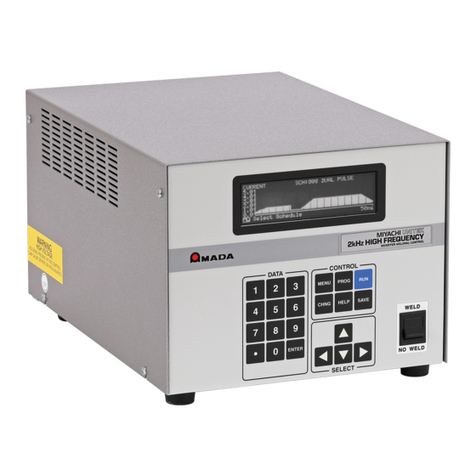
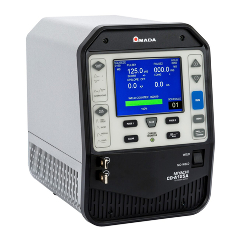
Amada S-2200CA User manual

990-412 REV G
INVERTER POWER SUPPLY
IS-2200CA/4500CA
OPERATION MANUAL

IS-2200CA/4500CA INVERTER POWER SUPPLY
ii 990-412
Copyright
2016 - 2020 AMADA WELD TECH INC.
The engineering designs, drawings and data contained herein are the proprietary work ofAMADAWELD
TECH and may not be reproduced, copied, exhibited or otherwise used without the written authorization
of AMADA WELD TECH.
Printed in the United States of America
Revision Record
Revision EO Date Basis of Revision
A 44470 11/16 Original publication
B 44551 02/17 Manual updates
C 44980 06/18 Update info on IS-2200CR & IS-4500CR
D 45546 07/19 Update EtherNet/IPTM terminology + content
E 45804 04/20 Update Company Name (Amada Weld Tech) + Model Names
F 45984 07/20 Update Fuse values in Maintenance section
G 46130 12/20 Update I/O Schematics in Appx B

IS-2200CA/4500CA INVERTER POWER SUPPLY
990-412 iii
FOREWORD
About This Equipment
Thank you for purchasing an AMADA WELD TECH IS-2200CA/4500CA Inverter Power Supply. For
the rest of this manual, the IS-2200CA/4500CA will be referred to simply as the Power Supply.
Upon receipt of your equipment, please thoroughly inspect it for shipping damage prior to its installation.
Should there be any damage, please immediately contact the shipping company to file a claim, and notify
us at: AMADA WELD TECH INC.
1820 South Myrtle Avenue
Monrovia, California 91016
Phone: (626) 303-5676
FAX: (626) 358-8048
E-mail: info@amadaweldtech.com
About This Manual
The purpose of this manual is to supply operating and maintenance personnel with the information needed
to properly and safely operate and maintain the IS-2200CA/4500CA Inverter Power Supply.
We have made every effort to ensure that the information in this manual is accurate and adequate. The
contents of this manual are subject to change without notice.
Should any questions arise, or if you have suggestions for improvement of this manual, please contact us
at the above location/numbers.
AMADA WELD TECH is not responsible for any loss due to improper use of this product.
This manual covers the following models:
Original Model Name
Original P/N
Current Model Name
Current P/N
IS-2200CR, 380V
IS-2200CR-xx-xx
→
IS-800CA/380
IS-800CA-xx-xx
IS-2200CR, 480V IS-2200CR-xx-xx
→
IS-800CA/480V IS-800CA-xx-xx
IS-4500CR, 480V IS-4500CR-xx-xx →IS-4500CA/480 IS-4500CA-xx-xx

IS-2200CA/4500CA INVERTER POWER SUPPLY
iv 990-412
CONTENTS Page
Chapter 1. System Description
Section I: Features .................................................................................................................................. 1-1
Basic and Advanced Units ...............................................................................................................1-1
Section II: System Components for IS-2200CA....................................................................................1-3
Front Panel .....................................................................................................................................1-3
WELD POWER Lamp .............................................................................................................1-3
READY Lamp ..........................................................................................................................1-3
START Lamp ........................................................................................................................... 1-3
WELD Lamp ............................................................................................................................1-3
TROUBLE Lamp .....................................................................................................................1-3
RESET Pushbutton Switch .......................................................................................................1-3
WELD ON/OFF Pushbutton Switch ........................................................................................1-3
Internal Components ........................................................................................................................1-4
Connecting Terminal Strip for External Input / Output Signals .............................................. 1-5
Charge Indicator Lamp .............................................................................................................1-6
External Connections ....................................................................................................................... 1-7
Cooling Water Pipe Connectors ...............................................................................................1-7
RS-485/RS-232C Connector ....................................................................................................1-8
Transformer Sensing Connector (Optional Toroidal Coil) ......................................................1-8
Section III: System Components for IS-4500CA...................................................................................1-9
Front Panel .....................................................................................................................................1-9
CONTROL and MONITOR Unit Connector .........................................................................1-10
WELD POWER Lamp ...........................................................................................................1-10
READY Lamp ........................................................................................................................1-10
START Lamp ......................................................................................................................... 1-10
WELD Lamp ..........................................................................................................................1-10
TROUBLE Lamp ...................................................................................................................1-10
RESET Pushbutton Switch .....................................................................................................1-10
WELD ON/OFF Pushbutton Switch ......................................................................................1-10
Internal Components ......................................................................................................................1-10
Power Module ........................................................................................................................1-12
Main PCB ............................................................................................................................... 1-12
ME-3050 Expansion Board .................................................................................................... 1-12
I/O Terminal Block .................................................................................................................1-12
Valve Transformer ..................................................................................................................1-12
Standby Transformer ..............................................................................................................1-12
Control Transformer ............................................................................................................... 1-12
Fuse Block .............................................................................................................................. 1-12
Driver Interface PCB ..............................................................................................................1-12
Capacitor Discharge Indicator ................................................................................................1-12

IS-2200CA/4500CA INVERTER POWER SUPPLY
990-412 v
CONTENTS (Continued) Page
Power and Ground Connections .................................................................................................... 1-13
Input Power Connections .......................................................................................................1-13
Circuit Breaker .......................................................................................................................1-14
Grounding Lug ....................................................................................................................... 1-14
Output Power Connections .....................................................................................................1-14
Rear Panel Base Connections ........................................................................................................ 1-14
Cooling Water Fittings ...........................................................................................................1-14
Secondary Current Sensor Input Connector ........................................................................... 1-14
Section IV: MA-660A Program Unit (“The Pendant”) ........................................................................1-15
TROUBLE RESET key .................................................................................................................1-16
CURSOR Keys ..............................................................................................................................1-16
+ON/-OFF Keys ............................................................................................................................1-16
ENTER Key ................................................................................................................................... 1-16
MENU Key ...................................................................................................................................1-17
Chapter 2. Installation And Setup
Section I: Planning .................................................................................................................................2-1
Environmental Factors ..................................................................................................................... 2-1
Space and Mounting Requirements ................................................................................................. 2-1
Power Requirements ........................................................................................................................2-2
Section II: Installation of IS-2200CA ....................................................................................................2-3
Unpacking .....................................................................................................................................2-3
Installation .....................................................................................................................................2-3
Mounting the Power Supply ..................................................................................................... 2-3
Electrical Connections .....................................................................................................................2-4
Input Power Connections ................................................................................................................. 2-5
Output Power Connections ..............................................................................................................2-7
Signal Sensing Connections ............................................................................................................ 2-8
IS-2200CA Cooling Water Requirements ......................................................................................2-9
IS-2200CA Cooling Water Hose Connections ................................................................................2-9
Section III: Installation of IS-4500CA ................................................................................................2-10
Unpacking ...................................................................................................................................2-10
Installation ...................................................................................................................................2-10
Mounting the Power Supply ................................................................................................... 2-10
Electrical Connections ...................................................................................................................2-11
Input Power Connections .......................................................................................................2-11
Output Power Connections .....................................................................................................2-12
Signal Sensing Connections ................................................................................................... 2-13
Breaker ...................................................................................................................................2-14
Input /Output Cable ....................................................................................................................... 2-15
This manual suits for next models
1
Table of contents
Other Amada Power Supply manuals

Amada
Amada CL-P115A User manual

Amada
Amada HF2 User manual

Amada
Amada MIH-200A User manual

Amada
Amada 125ADP User manual

Amada
Amada DC25 User manual

Amada
Amada IP-400B User manual

Amada
Amada PULSETIG MAWA-050A User manual

Amada
Amada 125DP User manual

Amada
Amada IS-800CR User manual

Amada
Amada CD-A Series User manual
Popular Power Supply manuals by other brands

Videx
Videx 520MR Installation instruction

Poppstar
Poppstar 1008821 Instructions for use

TDK-Lambda
TDK-Lambda LZS-A1000-3 Installation, operation and maintenance manual

TDK-Lambda
TDK-Lambda 500A instruction manual

Calira
Calira EVS 17/07-DS/IU operating instructions

Monacor
Monacor PS-12CCD instruction manual