Amada CL-H601A User manual

Scanner Head Unit
CL-H601A
OPERATION MANUAL
AA05OM1208351-06
Original instructions


1
CL-H601A
About This Documentation
Thank you for purchasing our CL-H601A Scanner Head Unit.
Please read this manual carefully to ensure correct use of the product. Keep the
manual handy after reading for future reference.
This document for the CL-H601A Scanner Head Unit describes installation,
maintenance and system specifications. For instructions for welding control using the
SWDraw3 application, refer to the manual for SWDraw3.
1. Note
•SUPERSCAN IV (SSIV) is either registered trademarks or trademarks of
RAYLASE GmbH in Germany and other countries.
•Company and product names in this manual are trademarks or registered
trademarks of their respective owners.
•Unauthorized reproduction of this manual in whole or part is prohibited.
•The contents of this manual are subject to change without notice.
•Every effort has been made to ensure the accuracy of this information. If you come
across oversights or errors, please notify your dealer.
•Be sure to read the user's manuals for any equipment used in conjunction with the
system (e.g., documentation for computer systems).
2. Symbols Used in this Manual
About This Documentation
Indicates instructions that must be followed to prevent hardware or software
damage or operating errors.
Indicates additional information on a particular topic.
Menus, icons, buttons,
windows, tabs Enclosed in brackets.
Example: Click the [OK] button.
Keyboard keys Enclosed in angle brackets.
Example: Press the <Tab> key.
References Enclosed in quotes.
Example: Refer to "Chapter 8-3.2 Changing Passwords" (page 5).
CAUTION
㪘㪫㪫㪜㪥㪫㪠㪦㪥

Contents
2
CL-H601A
Contents
About This Documentation....................................................................... 1
1 Note...................................................................................................................... 1
2 Symbols Used in this Manual............................................................................... 1
Chapter 1 Special Precautions ............................................................ 3
1 Safety Precautions ............................................................................................... 3
2 Operating Precautions.......................................................................................... 6
Chapter 2 Features.............................................................................. 8
Chapter 3 System Configuration.......................................................... 9
1 Overall Configuration............................................................................................ 9
2Name and Functions of Each Section................................................................ 10
Chapter 4 Installation......................................................................... 12
1 Unpacking .......................................................................................................... 12
2 Installation .......................................................................................................... 13
Chapter 5 Specifications.................................................................... 16
1 Basic Specifications ........................................................................................... 16
2 Lens Unit Lineup ................................................................................................ 17
3 Option................................................................................................................. 18
Chapter 6 Outline Drawing................................................................. 21
1 Scanner Head Unit............................................................................................. 21
2 Dimension of the Mounting Hole ........................................................................ 24
Chapter 7 Inspection and Parts Replacement ................................... 25
1 Before Inspection and Parts Replacement......................................................... 25
2 Parts Replacement............................................................................................. 25
3Protective Glass Inspection and Replacement................................................... 26

1. Safety Precautions
3
CL-H601A
Chapter 1 Special Precautions
1. Safety Precautions
Read these Safety Precautions thoroughly before use to ensure correct use of the
system.
•The precaution points indicated here are intended to ensure safe operation of the
system and prevent hazards or injury to users and other personnel.
They are important details relating to safety and must be read carefully.
•The indications have the following meanings.
Chapter 1 Special Precautions
Indicates that incorrect operation risks death or serious injury to personnel.
Indicates that incorrect operation may result in death or serious injury to
personnel.
Indicates that incorrect operation may result in injury to personnel or damage to
property.
Indicates prohibited actions and warns of actions not covered by the product warranty.
Indicates actions that must be performed by users.
The triangular symbol indicates details that supplement DANGER, WARNING, or CAUTION points.
DANGER
WARNING
CAUTION

1. Safety Precautions
4
CL-H601A
Never dismantle, repair, or modify the system. Doing so may result in electric
shock or fire.
Otherwise there is a risk of electric shock or fire. Do not attempt maintenance other than
that described in the Operation Manual.
Do not look into or touch the beam.
Direct and scattered laser light is dangerous. Looking directly at the laser source risks
blindness.
Wear protective goggles.
Protective goggles must always be worn when using the system.
Care must be taken even when wearing protective goggles, as looking directly at the laser
source through protective goggles risks blindness. Protective goggles attenuate the laser
beam, but does not block it.
Never subject parts of the body to laser radiation.
Otherwise there is a risk of burn injuries.
Do not damage power or connector cables.
Do not crush, twist, or pull cables. Damaged cables may result in electric shock, short-
circuiting, or fire.
Contact your dealer or us. if repair or replacement is necessary.
Connect securely using the specified cables.
Using cables with inadequate capacity or improper connections may result in fire or
electric shock.
Connect optical fibers securely.
Improper connection may result in burn injuries or fire.
Stop using the system if a problem arises.
If a problem occurs such as a burning smell, abnormal noise, overheating, or smoke
emission, continuing to use the system may result in electric shock or fire.
Contact your dealer or us immediately.
Use a stopper.
Laser radiation is hazardous to personnel.When operating the laser during maintenance
work, use a stopper (light-absorbing/scattering body capable of withstanding high
temperatures) to prevent laser emission beyond the stopper.
Wear protective work clothing.
Wear protective clothing such as gloves, long-sleeved clothing, and a leather apron.
Spatter will cause burn injuries if it lands on the skin.
DANGER
WARNING

1. Safety Precautions
5
CL-H601A
Chapter 1 Special Precautions
Keep away from water.
Subjecting electrical components to water may result in electric shock or short-circuiting.
Install in a firm location.
Otherwise there is a risk of injury if the system topples or falls from the installation
location.
Keep away from flammable materials.
Otherwise there is a risk of fire if spatter created during laser emission lands on
flammable materials.
If flammable materials cannot be removed from the vicinity, they must be covered with a
non-flammable cover.
Provide fire extinguishers.
Fire extinguishers must be provided in the welding work area in case of fire.
Inspect and maintain the system periodically.
Inspect and maintain the system periodically, repairing damaged parts and components
before use.
Do not point the laser beam at flammable materials.
Do not point the laser beam at flammable or combustible materials. Otherwise there is a
risk of fire.
Keep connector plugs clean and insert fully.
There is a risk of overheating and fire if dust is allowed to accumulate or if plugs are not
fully inserted.
Hold the plug body when inserting or removing.
There is a risk of damage to the cable and electric shock or fire if the cable is pulled to
unplug.
Do not cover with blankets or sheets.
Do not cover the system with blankets or sheets while in use. Otherwise there is a risk of
over-heating and fire.
CAUTION

2. Operating Precautions
6
CL-H601A
2. Operating Precautions
(1) When scanning highly reflective materials (such as gold, silver, copper, or aluminum),
be sure to contact us.
Depending on use conditions, the inside of the scanner head unit may be burnt.
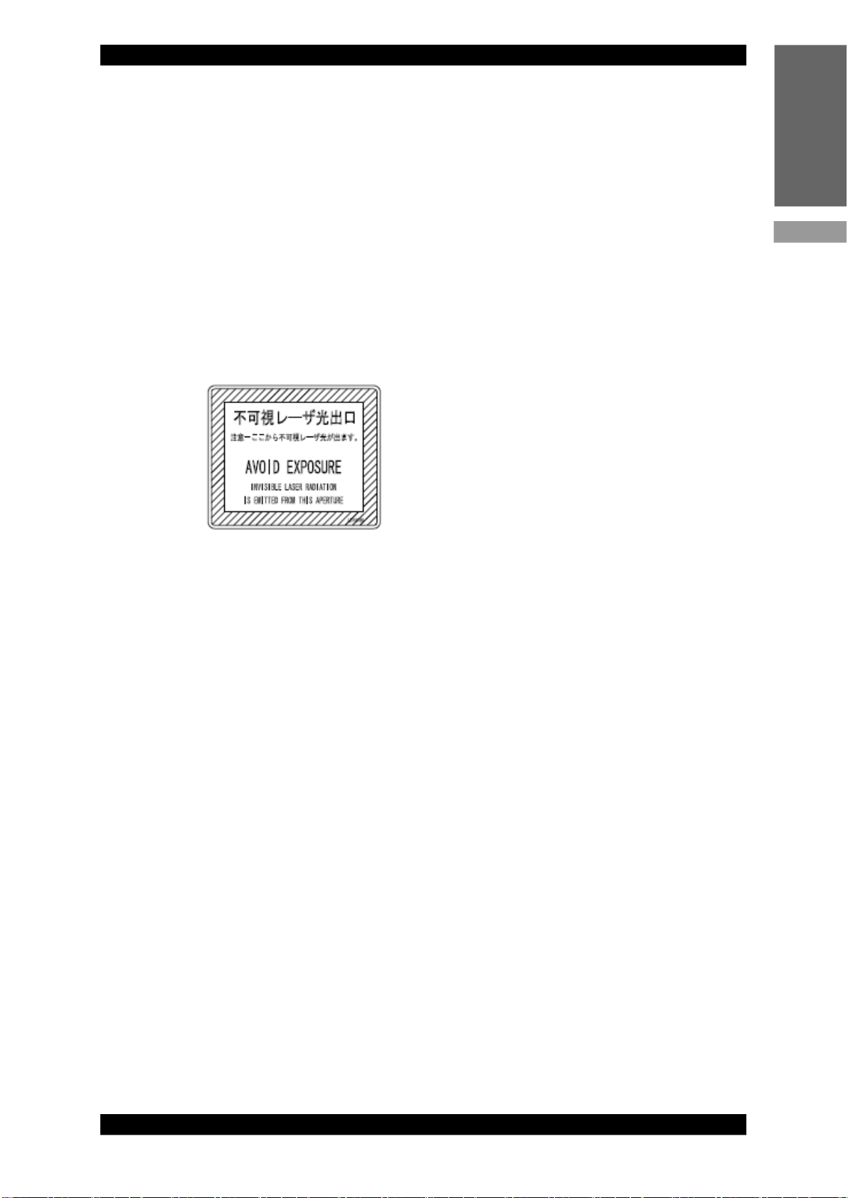
(2) A person knowledgeable about laser radiation and laser systems should be
appointed as a laser safety manager.
The laser safety manager should be responsible for managing the system key
switches, providing safety instruction to laser operators, and supervising
operations.
(3) Areas in which lasers are used must be partitioned from other areas by enclosing
with fences.
These areas should be managed by a supervisor and marked with signs to
prevent entry by unauthorized personnel.
(4) The system should be used in an ambient temperature range of 15°C to 35°C and
humidity 80% RH or lower with no sudden temperature fluctuations. Avoid using the
system in the following locations.
•Locations with dust or oil mist present
•Locations subject to vibration or impact
•Locations in which chemicals are used
•Locations subject to high noise
•Locations susceptible to condensation
•Locations with high concentrations of CO2, NOx, or SOx(The ion-exchange
resin life may be reduced by exposure to CO2concentrations of 0.1% or more.)
(5) There is a risk of condensation forming on the lens surface and debris adhering if the
ambient temperature changes suddenly such as when turning on the heating in cold
conditions. Avoid sudden temperature fluctuations. There is a likelihood that
condensation has formed if the output decreases during initial operation. Stop using
the system immediately, and check the lens surface if there is a likelihood of
condensation.
(6) The exterior of the system should be wiped clean using a soft or moist cloth. If the
exterior is particularly dirty, wipe clean using diluted detergent or alcohol.
(7) Do not drop foreign objects such as screws inside the system, as this may result in
failure of the system.
(8) Operate the system as described in the attached Operation Manual.
(9) Do not turn off the power switch of the laser control unit while a computer is
connected to the laser control unit.
(10) If a computer is connected, it will continue to access the memory card for about 15
seconds after going offline. During this time, do not turn off the power switch of the
laser control unit.
(11) If a computer is connected, never disconnect the LAN cable before turning off the
power switch of the laser control unit.

2. Operating Precautions
7
CL-H601A
Chapter 1 Special Precautions
(12) For more consistent scanning allow the unit to warm up for about 10 to 30 minutes
after turning it on. The warmup time varies depending on the temperature and
workpiece material.
(13) When a supervisor or operator enters the area where the laser is used, safety
measures not to exceed the MPE* level must be provided.
* MPE: The maximum level of permissible exposure of the eyes or skin to laser beams. Abbreviation of
Maximum Permissible Exposure.
* For other information on managing laser equipment or the MPE level, refer to the
following standards.
IEC Standards IEC60825-1 “Safety of laser products Part1: Equipment
Classifications, requirements and use’s guide”
[Warning/Caution label details]

8
CL-H601A
This product is a high-precision laser scanning system for welding which is used in the
emitter for laser light sent via optical fiber from the laser equipment and combined
with a laser control unit.
By combining the optional camera unit with the PC application SWDraw3 attached to
our laser control unit CL-E100A, scanning can be used more conveniently.
By combining the collimator and the fθlens, various spot diameters can be realized.
Chapter 2 Features

1. Overall Configuration
9
CL-H601A
Chapter 3 System Configuration
1. Overall Configuration
Chapter 3 System Configuration
Computer
Laser equipment
Scanner head unit
Laser control unit
Scanner power supply unit
Optical fiber
LAN cable
Scanner
connecting
cable
Power cable for scanner
Power cable for
control unit
Laser
equipment
connecting
cable
Camera
connecting
cable
Camera unit

2. Name and Functions of Each Section
10
CL-H601A
2. Name and Functions of Each Section
(1) Head I/F connector (XY2-100)
For connection to the XY2-100 connector of the laser control unit (CL-E100A)
using the scanner cable.
(2) Head I/F connector (SL2-100)
Not used.
(3) Power supply connector
For connection to the scanner power supply unit (CL-P148A) using the scanner
power cable.
(4) Collimator unit
For converting laser light output from the transmission fiber to parallel light.
(5) Image adjusting unit
For adjusting the focal point and the imaging position of the camera unit.
(6) CCD camera (option)
For observing the processing point.
For types, see "Chapter 5-3. Option" (page 18) .
(7) For observing the processing point.
(8) Scanner unit
The main unit of the scanner (SUPERSCAN IV manufactured by RAYLASE
GmbH).
(9) Mounting plate
For dimensions of the mounting hole, see "Chapter 6-2. Dimension of the
Mounting Hole" (page 24) .
(10) Water-cooled tube connector
Not used.
(11) fθlens
㻔㻠㻕
㻔㻢㻕
㻔㻡㻕
㻔㻥㻕
㻔㻣㻕
㻔㻞㻕
㻔㻤㻕
㻔㻟㻕
㻔㻝㻕
㻔㻝㻜㻕
㻔㻝㻝㻕

2. Name and Functions of Each Section
11
CL-H601A
Chapter 3 System Configuration
(12) Handle
Carry the Head Unit by holding this handle. Do not hold the collimator unit.
The positional relationship between coordinate axes XY and the center of
lens is as shown below.
CAUTION
㼄
㼅
㻔㻲㼞㼛㼚㼠㻕
㻔㻮㼍㼏㼗㻕

1. Unpacking
12
CL-H601A
1. Unpacking
1.1. Lifting and Transporting Container
1.2. Checking the Contents of Container
Verify that contents of the container agree with the following list.
The components marked with * are built in the scanner head unit.
Chapter 4 Installation
When moving the container, use a cart or ensure at least two people carry it.
Dimension Mass
(including contents)
Container for scanner
head unit and
accessories
Approx. 435 (H) x 570 (W) x 500 (D) mm Approx. 14 kg
Component Quantity
Scanner head unit 1
Label (LB1173123) 1
Label (LB1191496) 1
Operation manual 1
fθ lens * 1
Collimator lens unit * 1
Camera unit * 1
CAUTION

2. Installation
13
CL-H601A
Chapter 4 Installation
2. Installation
2.1. Installation Requirements
Refer to the following figure when installing the scanner head unit.
Scanning may produce dust and others, we recommend installing a dust collector.
The required clearance changes depending on the direction of the collimator unit.
㻰
㻱
㻯㻮
㻭
㻳
㻲
䊼
㻰
㻱
㻭
㻮
㻔㻮㼍㼏㼗㻕
㻻㼜㼠㼕㼏㼍㼘㻌㼒㼕㼎㼑㼞
㼙㼕㼚㻚㻌㼎㼑㼚㼐㼕㼚㼓㻌㼞㼍㼐㼕㼡㼟
㻹㼍㼏㼔㼕㼚㼕㼚㼓㻌㼟㼡㼞㼒㼍㼏㼑
㻔㻲㼞㼛㼚㼠㻕
㻔㼀㼛㼜㻕
㻔㻮㼍㼏㼗㻕
㻔㻲㼞㼛㼚㼠㻕
㼂㼑㼞㼠㼕㼏㼍㼘㻙㼠㼥㼜㼑㻌㼏㼛㼘㼘㼕㼙㼍㼠㼛㼞㻌㼡㼚㼕㼠
㻴㼛㼞㼕㼦㼛㼚㼠㼍㼘㻙㼠㼥㼜㼑㻌㼏㼛㼘㼘㼕㼙㼍㼠㼛㼞㻌㼡㼚㼕㼠

2. Installation
14
CL-H601A
* The type and size of the optical fiber connector are different according to the manufacturer and type
of the laser equipment to use, and a sufficient clearance may not be secured. Refer to the operation
manual for the laser equipment to be combined to install the scanner head unit.
Keep the following points in mind when installing the scanner head unit.
(1) The work distance is the distance from the outermost surface of the fθ lens’ protective
glass to the focal position. Depending on differences in scanning conditions and from
device to device, the work distance may result in slight variations. Make sure the
scanner head unit is installed to permit adjustment in the range of ±10 mm relative to
these values.
(2) Install the scanner head unit so that you can adjust and maintain level after
installation.
(3) For the scanner head unit mounting platform, use a sheet of metal at least 10 mm
thick.
(4) Protect the mounting platform from vibrations.
Vibrations of 0.1 G or less during operations are generally acceptable, but even
lesser vibrations under certain conditions may affect or distort scanning or lead
to damage.
(5) Keep the mounting platform separate from conveyor lines or other equipment to
prevent vibration and impact.
(6) When using two opposing scanner head units, install them so that the laser of neither
head is aimed at the other head.
A laser directed at parts within the other scanner head unit may burn the unit
interior.
Required Clearance and Mass Support
A. Clearance on fiber insertion part At least 400 mm *1
B. Clearance on right side At least 300 mm
C. Clearance on left side At least 300 mm
D. Clearance in front At least 300 mm
E. Clearance in back At least 350 mm *1
F. Mass Approx. 12 kg
G. Work distance See "Chapter 5-2. Lens Unit Lineup" (page 17) .
The optical fiber has its minimum bending radius. Refer to the operation
manual for the laser equipment connected to install the scanner head unit so
as not to bend the optical fiber beyond its minimum bending radius.
When moving the scanner head unit, support the head on right and left to
avoid touching the collimator unit or the lens. Do not hold the fiber or other
cables.
CAUTION
CAUTION

2. Installation
15
CL-H601A
Chapter 4 Installation
(7) When scanning highly reflective materials (such as gold, silver, copper, aluminum,
steel, or stainless steel), make sure the focal distance is correct.
Putting workpieces in a position other than the lens focal position may burn the
inside of the scanner head unit due to reflected light from the workpiece.
(8) Install the scanner head unit so that the laser is not aimed at the ceiling.
This precaution is intended to protect users from looking directly into laser
output unit and to facilitate maintenance.
2.2. Connections
(1) Avoid bundling control cables with other power cables.
The resulting electromagnetic noise may cause malfunctions.
(2) When connecting optical fibers, take care to avoid soiling or damaging the ends of
the fiber.
Retain the caps originally attached to the scanner head unit and optical fiber in a
safe location for future use. You will need them again if the optical fiber is
removed.
(3) Use the corresponding MF-C series or CL-P148A for the scanner power supply.
(4) In case of the camera unit attached, a camera and peripheral components are
coming with it. A camera and peripheral components have been assembled. Since
the angle and the focal point have been already adjusted, do not remove or move
them carelessly.
㻵㼙㼍㼓㼑㻌㼍㼐㼖㼡㼟㼠㼕㼚㼓㻌㼡㼚㼕㼠
㻱㼤㼜㼍㼚㼐㼑㼞
㻯㻯㻰㻌㼏㼍㼙㼑㼞㼍

1. Basic Specifications
16
CL-H601A
1. Basic Specifications
Chapter 5 Specifications
Item Specifications
Corresponding wavelength 1060 to 1080 nm, 650 nm (Guide beam)
Maximum allowable laser power 2000 W
Fiber connector type QBH
Ambient temperature 15°C to 35°C
Note: Contact us when using in ambient temperature below 5°C.
Ambient humidity 80% RH or lower (with no condensation or freeze)
Temperature during storage -10°C to 60°C (with no condensation or freeze)
Humidity during storage 80% RH or lower (with no condensation or freeze)
Vibration during transport (with
packaged) ASTM D 4728 Level2
Impact during transport (with packaged) ASTM D 4169-05 Level2
Dust, Oil mist IP54 (scanner unit only)
Electromagnetic
compatibility
standards
Immunity
Complied with the following:
IEC61000-4-2 (Electro-static immunity)
IEC61000-4-3 (Radiated field)
IEC61000-4-4 (Fast transient burst noise)
IEC61000-4-5 (Lightning surge)
IEC61000-4-6 (Conducted immunity)
IEC61000-4-8 (Magnetic field immunity)
IEC61000-4-11 (Dips/Interrupts)
Emission
Complied with the following:
EN55011 (Radiated disturbance)
EN55011 (Conducted disturbance)
Power supply voltage ±48 V
Current consumption Average: Approx. 2 A, Maximum: Approx. 5 A
External dimensions 233(W) mm × 480(D) mm × 375(H) mm (when using fθ lens: f306
and collimator: f150)
Mass Approx. 12 kg (excluding fθ lens and collimator)

2. Lens Unit Lineup
17
CL-H601A
Chapter 5 Specifications
2. Lens Unit Lineup
2.1. Fθ Lens
2.2. Collimator Lens
Depending on the laser equipment you use, some collimator lenses are not available.
f (mm) Work distance (mm) Machining area (mm)
f306 373.6±5 □150
f (mm)
f60
f80
f100
f120
f150

3. Option
18
CL-H601A
3. Option
3.1. Camera
The processing point can be observed by using the optional cameras.
By combining with the PC application SWDraw3, the USB3.0 camera SET and the
PoE camera SET can also use the Gridwork function and the Auto position alignment
function. For details of each function, see the operation manual for SWDraw3.
Each camera and image adjusting unit have been assembled to the scanner head unit
and adjusted. Do not remove them carelessly or rotate it.
3.1.1. USB3.0 camera SET
•Accessories
•Block diagram
Name Specification
Monochrome USB3.0 camera Monochrome 400,000 pixcels, USB3.0-supported camera
Image adjusting unit (x1.5) Magnification: x1.5
Cable for USB3.0 camera 5 m, black
Corresponding laser control unit
Corresponding MF-C series
Monochrome USB camera
Connect to either.
USB3.0 cable
* This connector is not used.
LAN
PC
Table of contents
Other Amada Welding System manuals

Amada
Amada MH-D500D User manual

Amada
Amada MH-H500D User manual

Amada
Amada ML-2050A-CE User manual

Amada
Amada IPB-5000B User manual

Amada
Amada ST-100A User manual

Amada
Amada LW500A User manual

Amada
Amada ML-2350AF User manual

Amada
Amada Thin-Line TL-080B Series User manual

Amada
Amada ML-7 Series User manual

Amada
Amada TCW User manual

Amada
Amada Miyachi Unitek STA-200A User manual

Amada
Amada ML-3030AS User manual

Amada
Amada PU-G User manual

Amada
Amada HF28/240 User manual

Amada
Amada GP-500A-P-DUAL User manual

Amada
Amada ML-2550A User manual

Amada
Amada MA-660A User manual

Amada
Amada 301H/115V User manual

Amada
Amada MH-1H-01 User manual

Amada
Amada MF-C300A-SF User manual