MH-D500D
1
Thank you for purchasing our Motor-Driven Resistance Welding Head MH-D500D.
・This operation manual explains its method of operation and precautions for use.
・Before using, read this operation manual carefully; after reading, save it in a proper place
where you can easily access.
Contents
1. Special Precautions
(1) Safety Precautions········································································ 1-1
(2) Precautions for Handling ································································ 1-4
(3) On Disposal ················································································ 1-4
2. Features ························································································· 2-1
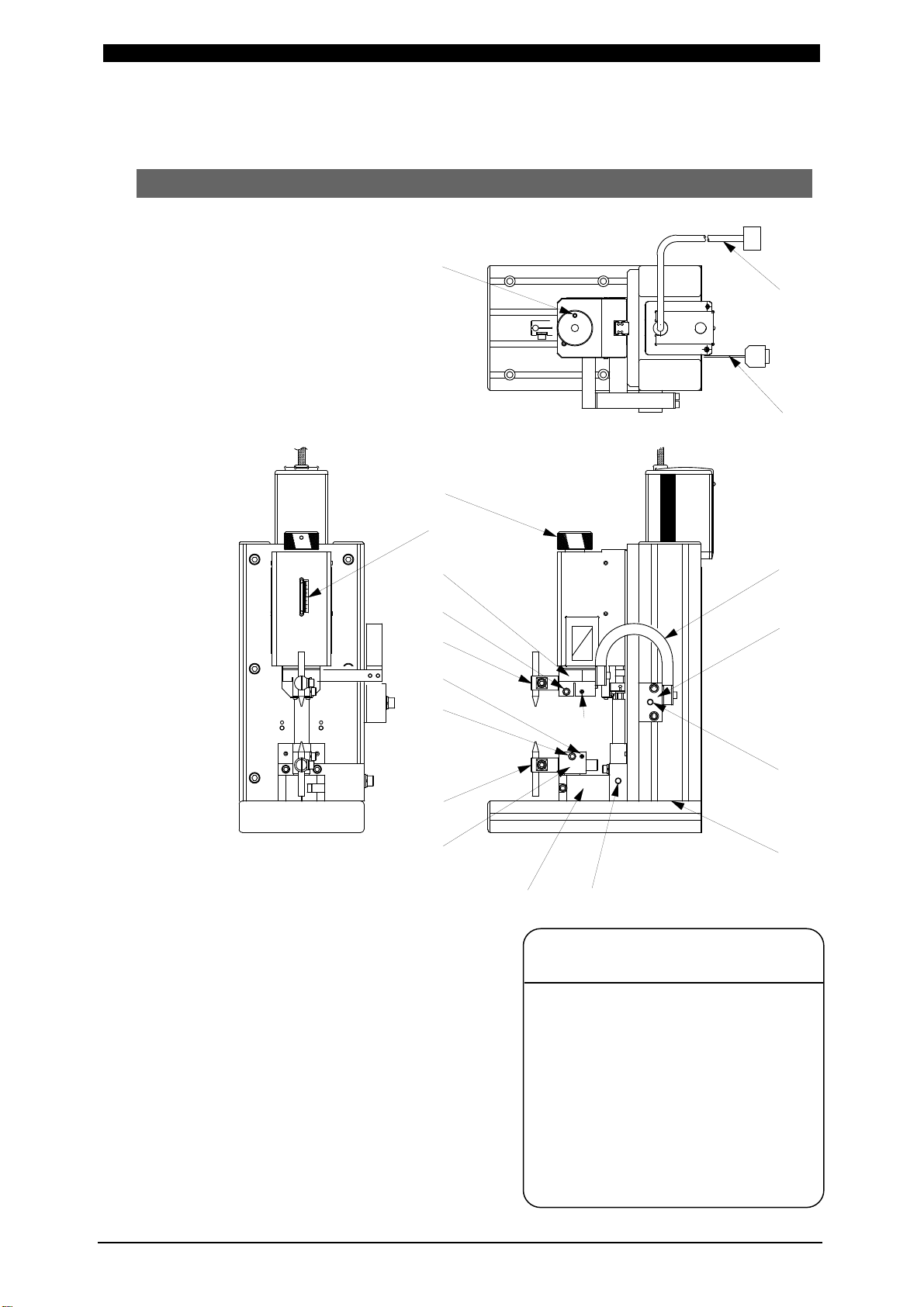
3. Name and Functions of Each Section
(1) Head·························································································· 3-1
(2) Controller Front Panel ··································································· 3-3
(3) Controller Rear Panel ···································································· 3-5
4. Interface
(1) Connection Diagram of External Input/Output Signal···························· 4-1
(2) I/O Connector ·············································································· 4-3
5. Installation and Connection ······························································ 5-1
6. Operation
(1) Getting Started············································································· 6-1
(2) Mode Setting ··············································································· 6-2
(3) Applying Power and Moving to Start Point ········································· 6-3
(4) Auto-Setting of Electrode Position ···················································· 6-4
(5) Manual Setting of Electrode Position ················································ 6-5
(6) Welding Work ·············································································· 6-10
(7) Measuring Weld Force··································································· 6-11
7. Fault Indications ·············································································· 7-1
8. User’s Maintenance
(1) Installing and Replacing Electrode (Separately sold)···························· 8-1
(2) Adjustment of Weld Force ······························································ 8-1
9. Specifications
(1) Specifications ·············································································· 9-1
(2) Accessories················································································· 9-1
(3) Separately Sold Items ··································································· 9-2
(4) Timing Chart················································································ 9-3
10. Data Communication
(1) Communication Specifications························································· 10-1
(2) Connection of Communication Connector·········································· 10-1
(3) Bidirectional Communication··························································· 10-3
11. Welding Head with Load Cell
(1) Connection of Load Cell Sensor to Indicator······································· 11-1
(2) Comparison Functions of Indicator ··················································· 11-1
(3) How to Hold HI-LO Limit Judging and Indicated Value at Indicator ·········· 11-3
(4) Calibration of Load Cell·································································· 11-4
12. Outline Drawings
(1) MH-D500D-00-00/01/30/31 Head····················································· 12-1
(2) MH-D500D-00-40/41 Head ····························································· 12-2