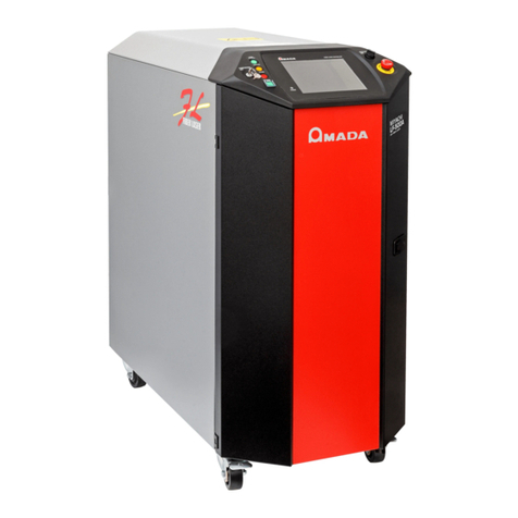
Amada Miyachi Unitek STA-200A User manual

990-351 Rev H
AC WELDER
STA SERIES
OPERATION MANUAL

STA SERIES AC CONTROLS
ii 990-351
Copyright © 2001, 2002, 2014 Amada Miyachi America
The engineering designs, drawings and data contained herein are the proprietary work of AMADA
MIYACHI AMERICA and may not be reproduced, copied, exhibited or otherwise used without the
written authorization of AMADA MIYACHI AMERICA .
Printed in the United States of America
Revision Record
Revision EO Date Basis of Revision
A 19123 12/01 Initial Release
B 19373 7/02
Addition of technical upgrades and features and inclusion of other
STA models.
C 19557 11/02
Inclusion of all STA Controls, and software upgrade to version
3.0.
D 20369 3/05 Updated technical information.
E 21467 7/07 Updated Schematics.
F 42840 10/13 Updated to Miyachi America name and logo.
G 43479 11/14 Updated to Amada Miyachi America name and logo.
H 43808 8/15 Updated to Amada Miyachi format, deleted obsolete models.

STA SERIES AC CONTROLS
990-351 iii
CONTACT US
Thank you for purchasing a Miyachi Unitek STA Series AC Control. This
unit is a component of a larger resistance welding system. Upon receipt,
please inspect it thoroughly for shipping damage before you install it. If
there is any damage, contact the shipping company immediately to file a
claim, and notify us at:
Amada Miyachi America
1820 South Myrtle Avenue
P.O. Box 5033
Monrovia, CA 91017-7133
Telephone: (626) 303-5676
FAX: (626) 358-8048
e-mail: [email protected]
Amada Miyachi America is not responsible for any losses due to improper
use of this product. The contents of this manual are subject to change
without notice. If you have any questions, find any errors/omissions, or if
you have suggestions for improving this manual, please contact us.
About This Equipment
The Control consists of a cabinet which contains the AC Main Timer
Board, SCR Driver Board, Control Panel Assembly, valve and power
transformers; SCR assemblies and snubbers and surge resistors. Unless
ordered otherwise, STA-200 Controls contain a circuit breaker that
disconnects when the front panel is opened. Four tabs on the rear surface
provide convenient mounting of the unit. The Control provides the user
with all of the controls for establishing all weld modes and timing.
Control options include a Valve Expansion Board, communication
capability, voltage monitoring, electronic pressure regulator control, force
monitoring and either primary current sensor or input connector(s) for
secondary current sensor(s). WeldLab software to extract and analyze
weld data is also available.
We have made every effort to ensure that the information in this manual is
accurate and adequate.
Should questions arise, or if you have suggestions for improvement of this
manual, please contact us at the above location/numbers.
Amada Miyachi America is not responsible for any loss due to improper
use of this product.

STA SERIES AC CONTROLS
iv 990-351
SAFETY NOTES
This instruction manual describes how to operate, maintain and service STA Series AC Controls, and
provides instructions relating to their SAFE use.
For SAFETY, and to effectively take advantage of the full capabilities of the workstation, please read
these instructions before attempting to use the workstation.
Procedures other than those described in this manual or not performed as prescribed in it, may expose
personnel to electrical hazards.
After reading this manual, retain it for future reference when any questions arise regarding the proper
and SAFE operation of the unit.
Please note the following conventions used in this manual:
WARNING: Comments marked this way warn the reader of actions, which, if not followed, might
result in immediate death or serious injury.
CAUTION: Comments marked this way warn the reader of actions which, if not followed, might result
in either damage to the equipment, or injury to the individual if subject to long-term exposure to the
indicated hazard.
WARNINGS
HIGH VOLTAGE is used in the operation of this equipment.
DEATH ON CONTACT may result if personnel fail to observe the
safety precautions labeled on the equipment and noted in this manual.
WHEN WELDING always wear safety glasses.

STA SERIES AC CONTROLS
990-351 v
CONTENTS Page
Revision Record ......................................................................................................................................... ii
Contact Us ..............................................................................................................................................iii
Safety Notes .............................................................................................................................................. iv
Chapter 1. Description
Section I: Features ..................................................................................................................................1-1
Overview ..........................................................................................................................................1-1
Standard Features .............................................................................................................................1-1
Optional Features .............................................................................................................................1-1
Section II: Major Components ................................................................................................................1-3
Major Components ..........................................................................................................................1-3
Front Panel Controls and Indicators ................................................................................................1-5
LCD Display .............................................................................................................................1-5
Ready ........................................................................................................................................1-5
Error ..........................................................................................................................................1-5
Weld .........................................................................................................................................1-5
Start ...........................................................................................................................................1-5
Program/Save ...........................................................................................................................1-5
Weld ON/OFF ..........................................................................................................................1-6
Data + ON | OFF ......................................................................................................................1-6
Cursor .......................................................................................................................................1-6
Schedule ...................................................................................................................................1-6
Valves .......................................................................................................................................1-6
Modes .......................................................................................................................................1-7
Reset .........................................................................................................................................1-7
Monitor .....................................................................................................................................1-7
Stepper ......................................................................................................................................1-7
Programming Lock ...................................................................................................................1-7
External Connectors .........................................................................................................................1-7
Cylinder Air Hose Connections ....................................................................................................... 1-8
Internal Access .................................................................................................................................1-8
Option Cards ....................................................................................................................................1-9
Electrical Connections .....................................................................................................................1-9
Chapter 2. Installation and Setup
Section I: Planning for Installation ..........................................................................................................2-
1
Environmental Factors .....................................................................................................................2-1
Space and Mounting Requirements .................................................................................................2-1
Power Requirements ........................................................................................................................2-1
Cooling Water Requirements .........................................................................................................2-1

STA SERIES AC CONTROLS
vi 990-351
CONTENTS (Continued) Page
Section II: Control Set-up ......................................................................................................................2-2
Unpacking ........................................................................................................................................2-2
Installation .......................................................................................................................................2-2
Mounting the Control ......................................................................................................................2-2
Connecting Electrical Power ...........................................................................................................2-2
Secondary Current Sensing ..............................................................................................................2-3
Placement of Secondary Current Coils .....................................................................................2-3
Valve Transformer Wiring Connections ..................................................................................2-3
Cooling Water Hose Connections ...................................................................................................2-3
Input/Output Signal Connections ....................................................................................................2-3
Chapter 3. Using STA Series Control Functions
Section I: Overview ............................................................................................................................... 3-1
Section II: Schedule Screen ...................................................................................................................3-2
SCHEDULE # ................................................................................................................................3-2
PROGRAM/SAVE ..........................................................................................................................3-2
Links ............................................................................................................................................3-2
SQD (Squeeze Delay) ......................................................................................................................3-2
SQZ (Squeeze Time) .......................................................................................................................3-2
UP1 (Weld 1 Upslope Time) ...........................................................................................................3-2
W1 (Weld 1 Time) ...........................................................................................................................3-2
DN1 (Weld 1 downslope time) ........................................................................................................3-3
CO (cool time) .................................................................................................................................3-3
UP2 (Weld 2 Upslope Time) ...........................................................................................................3-3
W2 (Weld 2 Time) ...........................................................................................................................3-3
DN2 (Weld 2 Downslope Time) ......................................................................................................3-3
HLD –hold time ...............................................................................................................................3-3
OFF ............................................................................................................................................3-3
MODE ............................................................................................................................................3-3
CURRENT SETTING .....................................................................................................................3-3
CH (Force Output Channel) .............................................................................................................3-3
FORCE ...........................................................................................................................................3-3
ElecValve (Valve Associated with Electrode) ................................................................................3-3
SCR # (SCR Number) .....................................................................................................................3-3
IMPULSE (Quantity of Weld 2 Operations) ...................................................................................3-3
COPY TO # – Copying a schedule .................................................................................................3-4
Section III: Valves Screen .....................................................................................................................3-5

SCHEDULE # .................................................................................................................................3-5
PROGRAM/SAVE ..........................................................................................................................3-5
ELECTRODE VALVE .................................................................................................................... 3-5
STATUS ..........................................................................................................................................3-5
COUNT ............................................................................................................................................3-5


STA SERIES AC CONTROLS
990-351 vii
Page
Section IV: Monitor Screen ...................................................................................................................3-6
CURR (Weld Current) .....................................................................................................................3-6
COND (Conduction Angle) .............................................................................................................3-6
VOLTS ............................................................................................................................................3-6
FORCE(LBS) ..................................................................................................................................3-6
LO (Low Current Limit) .................................................................................................................. 3-6
HI (High Current Limit) ..................................................................................................................3-6
COND. LIMIT (Conduction Angle Limit) ......................................................................................3-7
Counts (MONITOR COUNTS Screen) ......................................................................................3-7
Section V: Monitor Counts Screen ........................................................................................................3-8
SCHEDULE # (Schedule number) ..................................................................................................3-8
WELD COUNT ...............................................................................................................................3-8
WELD COUNT LIMIT ...................................................................................................................3-8
SET WELD COUNT = 0 .................................................................................................................3-8
STEP # (Step Number) ....................................................................................................................3-8
STEP COUNT .................................................................................................................................3-8
ELECT. VALVE .............................................................................................................................3-8
STEP COUNT .................................................................................................................................3-8
ELECT. VALVE .............................................................................................................................3-8
Section VI: Mode Screen .......................................................................................................................3-9
SCHEDULE # (Schedule Number) ................................................................................................3-9
PROGRAM/SAVE ..........................................................................................................................3-9
START ............................................................................................................................................3-9
WELD MODE .............................................................................................................................. 3-10
Spot Weld Mode .....................................................................................................................3-10
Repeat Mode ...........................................................................................................................3-10
Successive Mode ....................................................................................................................3-10
Chaining Mode .......................................................................................................................3-10
LINKED SCHED .......................................................................................................................3-11
Section VII: Linked Schedules Screen ................................................................................................3-12
Reference .......................................................................................................................................3-12
SCHD ..........................................................................................................................................3-12
CURR WELD CNT (Weld Counts for Schedule) .........................................................................3-12
WELD MODE ...............................................................................................................................3-12
ERROR ..........................................................................................................................................3-12
Section VIII: System Values Screens ..................................................................................................3-13
System Values Screen 1 .................................................................................................................3-13
FULL CURR. (Full Current) ..................................................................................................3-13
MAX # OF SCR (SCRs in Control) .......................................................................................3-13
TURNS RATIO ......................................................................................................................3-13

STA SERIES AC CONTROLS
viii 990-351
CONTENTS (Continued) Page
CNTRL MODE (Control Mode) ............................................................................................3-13
BIN. SCHED. SELECT (Binary Schedule Select) ................................................................3-13
FIRING SWITCH ..................................................................................................................3-13
COIL .......................................................................................................................................3-13
CONTRAST+/– ......................................................................................................................3-13
NUM VALVES (Number of Valves)......................................................................................3-14
VALVES STATUS ................................................................................................................3-14
MODE ....................................................................................................................................3-14
MORE (System Value Screen 2) ............................................................................................3-14
System Values Screen 2 .................................................................................................................3-14
87° DELAY (ON or OFF) ......................................................................................................3-14
END OUTPUT .......................................................................................................................3-14
STEP END OUTPUT .............................................................................................................3-14
WELD ON/OFF .....................................................................................................................3-14
LOW LINE ALARM ............................................................................................................3-14
AUTO RESET ........................................................................................................................3-14
ERROR OUTPUT ..................................................................................................................3-15
SET DEFAULTS ....................................................................................................................3-15
MASTER CNTL ....................................................................................................................3-15
UNIT ADDRESS ....................................................................................................................3-15
System Values Screen 3 .................................................................................................................3-15
RETRACTION .......................................................................................................................3-15
Pressure Switch ......................................................................................................................3-16
Output Force ...........................................................................................................................3-16
Monitored Volts ..............................................................................................................3-16
Monitored Time ...............................................................................................................3-16
Back Pressure .........................................................................................................................3-16
Screen 2 ...............................................................................................................................3-16
Section IX. System Valve Status Screen ............................................................................................. 3-17
VALVE (Valve Numbers) ......................................................................................................3-17
CNT (Weld Count) .................................................................................................................3-17
RESET (Reset Count to Zero) ................................................................................................ 3-17
SCR (SCR Used With Each Valve) ........................................................................................3-17
Section X: Force Calibration Screen ....................................................................................................3-18
Section XI. Stepper Screen ..................................................................................................................3-19
VALVE NUM ...............................................................................................................................3-19
SCR# (SCR Number) ...................................................................................................................3-19
STEPPER (ON/OFF) ....................................................................................................................3-19
COUNT ..........................................................................................................................................3-19
HEAT% .........................................................................................................................................3-19

STA SERIES AC CONTROLS
990-351 ix
Page
Chapter 4. Operating Instructions
Section I: Introduction ........................................................................................................................... 4-1
Overview ..........................................................................................................................................4-1
General Operator Safety ..................................................................................................................4-1
Section II: Preparing for Operation ........................................................................................................4-2
Turning the Equipment ON .............................................................................................................4-2
Pre-Operational Setup ......................................................................................................................4-3
Section III: Setup Messages ....................................................................................................................4-4
Section IV. Operation ............................................................................................................................ 4-6
Spot Welds .......................................................................................................................................4-7
Continuous Seam Weld ...................................................................................................................4-8
Cascading (Multiple SCRs) .............................................................................................................4-9
Section V: Operational Messages ........................................................................................................4-11
Major Run-Time Error Messages ..................................................................................................4-11
Minor Run-Time Error Messages ..................................................................................................4-13
Section VI: Shutdown ..........................................................................................................................4-15
Emergency Shutdown ....................................................................................................................4-15
Normal Shutdown ..........................................................................................................................4-15
Chapter 5. Maintenance
Section I: Precautions ............................................................................................................................5-1
Section II: General Information .............................................................................................................5-1
General Maintenance Procedures ....................................................................................................5-1
Cooling Maintenance – Water Draining ..........................................................................................5-1
Fuse Replacement ............................................................................................................................5-2
Principles of Operation ....................................................................................................................5-2
Wiring Diagram ...............................................................................................................................5-3
Section III. Standard Components Replacement ...................................................................................5-5
AC Timer Main Board .....................................................................................................................5-5
Power Transformer T1 .....................................................................................................................5-7
Power Transformer T2 .....................................................................................................................5-7
Valve Transformer, T3 ....................................................................................................................5-7
Surge Resistors ...............................................................................................................................5-7
Snubber ............................................................................................................................................5-8
SCR Drive Board .............................................................................................................................5-8
Control Panel Assembly ..................................................................................................................5-9
Section IV. Optional Components Replacement .................................................................................5-10
Optional Primary Current Sensor ..................................................................................................5-10
Optional Secondary Current Sensor Connector .............................................................................5-10
Optional Key Lock ........................................................................................................................5-11
Optional SCR Assembly, 600,1200, 1800, and 2200 Amp ........................................................... 5-11

STA SERIES AC CONTROLS
x 990-351
CONTENTS (Continued) Page
Section V. Spare Parts ..........................................................................................................................5-12
Section VI. Repair ................................................................................................................................5-13
Section VII. Storage and Shipment ......................................................................................................5-13
Preparation for Storage or Shipment .............................................................................................5-13
Packing for Storage or Shipment ................................................................................................... 5-13
Appendix A. Technical Specifications ............................................................................................... A-1
Appendix B. Electrical And Data Connections .................................................................................B-1
Appendix C. SCR, Wire Gauge, And Circuit Breaker Selection ....................................................C-1
Appendix D. System Timing .............................................................................................................. D-1
Appendix E. Cascade Option ..............................................................................................................E-1
Appendix F. Valve Expansion Board Option ....................................................................................F-1
Appendix G. Voltage Monitor Board Option ................................................................................... G-1
Appendix H. Force Control Option.................................................................................................... H-1
Appendix I. Pressure Control Option..................................................................................................I-1
Appendix J. Communications ..............................................................................................................J-1
Appendix K. Circuit Modification for External Transformer Thermostat .................................. K-1
Appendix L. Default Initializations ....................................................................................................L-1
Index .....................................................................................................................................Index-1

STA SERIES AC CONTROLS
990-351 xi
LIMITED WARRANTY
1. (a) Subject to the exceptions and upon the conditions set forth herein, Seller warrants to Buyer that
for a period of one (1) year from the date of shipment (“Warranty Period”), that such Goods will be free
from material defects in material and workmanship.
(b) Notwithstanding the foregoing and anything herein to the contrary, the warranty set forth in this
Section 1 shall be superseded and replaced in its entirety with the warranty set forth on Exhibit A
hereto if the Goods being purchased are specialty products, which include, without limitation, laser
products, fiber markers, custom systems, workstations, Seller-installed products, non-catalogue
products and other custom-made items (each a “Specialty Products.”
(c) EXCEPT FOR THE WARRANTY SET FORTH IN SECTION 1(A), SELLER MAKES NO
WARRANTY WHATSOEVER WITH RESPECT TO THE GOODS (INCLUDING ANY SOFTWARE) OR
SERVICES, INCLUDING ANY (a) WARRANTY OF MERCHANTABILITY; (b) WARRANTY OF
FITNESS FOR A PARTICULAR PURPOSE; (c) WARRANTY OF TITLE; OR (d) WARRANTY
AGAINST INFRINGEMENT OF INTELLECTUAL PROPERTY RIGHTS OF A THIRD PARTY;
WHETHER EXPRESS OR IMPLIED BY LAW, COURSE OF DEALING, COURSE OF
PERFORMANCE, USAGE OF TRADE OR OTHERWISE.
(d) Products manufactured by a third party and third party software (“Third Party Product”) may
constitute, contain, be contained in, incorporated into, attached to or packaged together with, the
Goods. Third Party Products are not covered by the warranty in Section 1(a). For the avoidance of
doubt, SELLER MAKES NO REPRESENTATIONS OR WARRANTIES WITH RESPECT TO ANY
THIRD PARTY PRODUCT, INCLUDING ANY (a) WARRANTY OF MERCHANTABILITY; (b)
WARRANTY OF FITNESS FOR A PARTICULAR PURPOSE; (c) WARRANTY OF TITLE; OR (d)
WARRANTY AGAINST INFRINGEMENT OF INTELLECTUAL PROPERTY RIGHTS OF A THIRD
PARTY; WHETHER EXPRESS OR IMPLIED BY LAW, COURSE OF DEALING, COURSE OF
PERFORMANCE, USAGE OF TRADE OR OTHERWISE. Notwithstanding the foregoing, in the event
of the failure of any Third Party Product, Seller will assist (within reason) Buyer (at Buyer’s sole
expense) in obtaining, from the respective third party, any (if any) adjustment that is available under
such third party’s warranty.
(e) Seller shall not be liable for a breach of the warranty set forth in Section 1(a) unless: (i) Buyer gives
written notice of the defect, reasonably described, to Seller within five (5) days of the time when Buyer
discovers or ought to have discovered the defect and such notice is received by Seller during the
Warranty Period; (ii) Seller is given a reasonable opportunity after receiving the notice to examine such
Goods; (iii) Buyer (if requested to do so by Seller) returns such Goods (prepaid and insured to Seller at
1820 South Myrtle Avenue, Monrovia, CA 91016or to such other location as designated in writing by
Seller) to Seller pursuant to Seller’s RMA procedures and Buyer obtains a RMA number from Seller
prior to returning such Goods for the examination to take place; and (iii) Seller reasonably verifies
Buyer’s claim that the Goods are defective and that the defect developed under normal and proper use.
(f) Seller shall not be liable for a breach of the warranty set forth in Section 1(a) if: (i) Buyer makes any
further use of such Goods after giving such notice; (ii) the defect arises because Buyer failed to follow
Seller’s oral or written instructions as to the storage, installation, commissioning, use or maintenance of
the Goods; (iii) Buyer alters or repairs such Goods without the prior written consent of Seller; or (iv)
repairs or modifications are made by persons other than Seller’s own service personnel, or an
authorized representative’s personnel, unless such repairs are made with the written consent of Seller
in accordance with procedures outlined by Seller.
(g) All expendables such as electrodes are warranted only for defect in material and workmanship
which are apparent upon receipt by Buyer. The foregoing warranty is negated after the initial use.

STA SERIES AC CONTROLS
xii 990-351
(h) Subject to Section 1(e) and Section 1(f) above, with respect to any such Goods during the Warranty
Period, Seller shall, in its sole discretion, either: (i) repair or replace such Goods (or the defective part)
or (ii) credit or refund the price of such Goods at the pro rata contract rate, provided that, if Seller so
requests, Buyer shall, at Buyer’s expense, return such Goods to Seller.
(i) THE REMEDIES SET FORTH IN SECTION 1(H) SHALL BE BUYER’S SOLE AND EXCLUSIVE
REMEDY AND SELLER’S ENTIRE LIABILITY FOR ANY BREACH OF THE LIMITED WARRANTY
SET FORTH IN SECTION 1(A). Representations and warranties made by any person, including
representatives of Seller, which are inconsistent or in conflict with the terms of this warranty, as set
forth above, shall not be binding upon Seller.

STA SERIES AC CONTROLS
990-351 xiii
Exhibit A
Warranty for “Specialty Products”
Limited Warranty
EXCEPT FOR THE WARRANTY SET FORTH BELOW IN THIS EXHIBIT A, SELLER MAKES NO
WARRANTY WHATSOEVER WITH RESPECT TO THE GOODS (INCLUDING ANY SOFTWARE) OR
SERVICES, INCLUDING ANY (a) WARRANTY OF MERCHANTABILITY; (b) WARRANTY OF
FITNESS FOR A PARTICULAR PURPOSE; (c) WARRANTY OF TITLE; OR (d) WARRANTY
AGAINST INFRINGEMENT OF INTELLECTUAL PROPERTY RIGHTS OF A THIRD PARTY;
WHETHER EXPRESS OR IMPLIED BY LAW, COURSE OF DEALING, COURSE OF
PERFORMANCE, USAGE OF TRADE OR OTHERWISE.
Warranty Period: The Warranty Period for Specialty Products is for one (1) year, and the Warranty
Period for laser welders and laser markers is two (2) years (unlimited hours), and the Warranty Period
for the laser pump diodes or modules is two (2) years or 10,000 clock hours, whichever occurs first (as
applicable, the “Warranty Period”). The Warranty Period begins as follows: (i) on orders for Goods
purchased directly by Buyer, upon installation at Buyer’s site or thirty (30) days after the date of
shipment, whichever occurs first; or (ii) on equipment purchased by a Buyer that is an OEM or systems
integrators, upon installation at the end user’s site or six (6) months after the date of shipment,
whichever occurs first.
Acceptance Tests: Acceptance Tests (when required) shall be conducted at Amada Miyachi
America, Inc., Monrovia, CA, USA (the “Testing Site”) unless otherwise mutually agreed in writing prior
to issuance or acceptance of the Acknowledgement. Acceptance Tests shall consist of a final visual
inspection and a functional test of all laser, workstation, enclosure, motion and accessory hardware.
Acceptance Tests shall include electrical, mechanical, optical, beam delivery, and software items
deliverable under the terms of the Acknowledgement. Terms and conditions for Additional Acceptance
Tests either at Seller’s or Buyer’s facility shall be mutually agreed in writing prior to issuance or
acceptance of the Acknowledgement.
Performance Warranty: The system is warranted to pass the identical performance criteria at Buyer’s
site as demonstrated during final Acceptance Testing at the Testing Site during the Warranty Period, as
provided in the Acknowledgement. Seller explicitly disclaims any responsibility for the process results
of the laser processing (welding, marking, drilling, cutting, etc.) operations.
Exclusions: Seller makes no warranty, express or implied, with respect to the design or operation of
any system in which any Seller’s product sold hereunder is a component.
Limitations: The limited warranty set forth on this Exhibit A does not cover loss, damage, or defects
resulting from transportation to Buyer’s facility, improper or inadequate maintenance by Buyer, Buyer-
supplied software or interfacing, unauthorized modification or misuse, operation outside of the
environmental specifications for the equipment, or improper site preparation and maintenance. This
warranty also does not cover damage from misuse, accident, fire or other casualties of failures caused
by modifications to any part of the equipment or unauthorized entry to those portions of the laser which
are stated. Furthermore, Seller shall not be liable for a breach of the warranty set forth in this Exhibit A
if: (i) Buyer makes any further use of such Goods after giving such notice; (ii) the defect arises because
Buyer failed to follow Seller’s oral or written instructions as to the storage, installation, commissioning,
use or maintenance of the Goods; (iii) Buyer alters or repairs such Goods without the prior written
consent of Seller; or (iv) repairs or modifications are made by persons other than Seller’s own service
personnel, or an authorized representative’s personnel, unless such repairs are made with the written
consent of Seller in accordance with procedures outlined by Seller.

STA SERIES AC CONTROLS
xiv 990-351
Seller further warrants that all Services performed by Seller’s employees will be performed in a good
and workmanlike manner. Seller’s sole liability under the foregoing warranty is limited to the obligation
to re-perform, at Seller’s cost, any such Services not so performed, within a reasonable amount of time
following receipt of written notice from Buyer of such breach, provided that Buyer must inform Seller of
any such breach within ten (10) days of the date of performance of such Services.
Seller shall not be liable for a breach of the warranty set forth in this Exhibit A unless: (i) Buyer gives
written notice of the defect or non-compliance covered by the warranty, reasonably described, to Seller
within five (5) days of the time when Buyer discovers or ought to have discovered the defect or non-
compliance and such notice is received by Seller during the Warranty Period; (ii) Seller is given a
reasonable opportunity after receiving the notice to examine such Goods and (a) Buyer returns such
Goods to Seller’s place of business at Buyer’s cost (prepaid and insured); or (b) in the case of custom
systems, Seller dispatches a field service provider to Buyer’s location at Buyer’s expense, for the
examination to take place there; and (iii) Seller reasonably verifies Buyer’s claim that the Goods are
defective or non-compliant and the defect or non-compliance developed under normal and proper use.
All consumable, optical fibers, and expendables such as electrodes are warranted only for defect in
material and workmanship which are apparent upon receipt by Buyer. The foregoing warranty is
negated after the initial use.
No warranty made hereunder shall extend to any product whose serial number is altered, defaced, or
removed.
Remedies: With respect to any such Goods during the Warranty Period, Seller shall, in its sole
discretion, either: repair such Goods (or the defective part). THE REMEDIES SET FORTH IN THE
FOREGOING SENTENCE SHALL BE BUYER’S SOLE AND EXCLUSIVE REMEDY AND SELLER’S
ENTIRE LIABILITY FOR ANY BREACH OF THE LIMITED WARRANTY SET FORTH IN THIS
EXHIBIT A. Representations and warranties made by any person, including representatives of Seller,
which are inconsistent or in conflict with the terms of this warranty, as set forth above, shall not be
binding upon Seller.
Products manufactured by a third party and third party software (“Third Party Product”) may
constitute, contain, be contained in, incorporated into, attached to or packaged together with, the
Goods. Third Party Products are not covered by the warranty in this Exhibit A. For the avoidance of
doubt, SELLER MAKES NO REPRESENTATIONS OR WARRANTIES WITH RESPECT TO ANY
THIRD PARTY PRODUCT, INCLUDING ANY (a) WARRANTY OF MERCHANTABILITY; (b)
WARRANTY OF FITNESS FOR A PARTICULAR PURPOSE; (c) WARRANTY OF TITLE; OR (d)
WARRANTY AGAINST INFRINGEMENT OF INTELLECTUAL PROPERTY RIGHTS OF A THIRD
PARTY; WHETHER EXPRESS OR IMPLIED BY LAW, COURSE OF DEALING, COURSE OF
PERFORMANCE, USAGE OF TRADE OR OTHERWISE. Notwithstanding the foregoing, in the event
of the failure of any Third Party Product, Seller will assist (within reason) Buyer (at Buyer’s sole
expense) in obtaining, from the respective third party, any (if any) adjustment that is available under
such third party’s warranty.

STA SERIES AC CONTROLS
990-351 1-1
Chapter 1
SYSTEM DESCRIPTION
Section I: Features
Overview
For the rest of this manual, STA Series Single-Phase AC welding Controls will simply be referred to
as “the Control.” The STA Series has a wide variety of options, some are installed at the time of
purchase, some may be added later. In addition, the operating controls and LCD display screen on the
STA-200A Control may be installed on the front or side of the Control, depending on your space
requirements. As a result, each Control is essentially “custom-built” to your specifications even though
it is assembled using standard Amada Miyachi America components.
This manual describes the most common or “typical” components and options. If you have questions
about custom items in your Control that are not covered in this manual, contact Amada Miyachi
America using the phone, e-mail, or mailing information in the front of this manual.

CHAPTER 1: DESCRIPTION
STA SERIES AC CONTROLS
1-2 990-351
Standard Features
Operates on 50Hz or 60Hz, self-detecting, no adjustments needed.
Multiple pulse capability.
Controlled current ramps.
300, 600, 1200, 1800, or 2200 amp SCRs with constant current control.
Water-cooling of the 600A and larger SCR assemblies.
Programming features with LCD display.
Programmable for spot, repeat, successive, or chaining modes.
Continuous seam weld and roll spot seam welding capabilities.
Programmable for 64 welding schedules.
Valve drivers for up to four user-programmable valves are included in the basic unit.
Supports air-actuated Retraction Valves.
Optional Features
A circuit breaker that removes power to the Control when the door is opened (STA-200
through STA-800).
A Communications card that allows remote data collection and remote programming of the
Control.
A Cascade Board Option that allows a Control to operate multiple SCRs. Depending upon the
model, up to 8 SCRs can be cascade fired.
A Valve Expansion Option to increase user-programmable valve-driver capability to 12 valves.
A Voltage Monitor Option that allows you to compare results against high and low limits, and
monitor either peak or average voltage. This feature allows you to select when the voltage is
monitored, either during both weld periods (excluding up/downslope) or during the last cycle of
each weld only, which is useful for welding to a specific resistance.
A Force Control (Force Output) Option that can control up to 8 separate (user supplied)
electronic pressure regulators. Force is programmed in pounds using front panel controls. The
Control makes calculations to create accurate air pressure. Calibration is a simple 2-step
procedure using front panel controls.
A Pressure Control Option (Force Input) that uses differential pressure sensors is available for
up to eight channels. You may use this feature in a Force-Firing function (welds only when
correct pressure is reached), or as a pressure monitor to see if air pressure is in the desired
range. Force firing can reduce cycle time by eliminating the need to program squeeze time, and
it assures that every weld is made at the optimum force.
High, low and Firing Force limits are programmed in pounds using front panel controls.
Calibration is a simple 2-step procedure using front panel controls. Calibration correlates the
pounds desired to the equivalent air pressure. This feature will check the air pressure for up to
5 seconds at the start of the squeeze delay period. If the force is within limits, the weld will
continue. Otherwise, the weld will be aborted and an alarm will be triggered. If the pressure
was out of limits at the end of a weld an alarm will be triggered.
NOTE: This feature requires presence of the Force Control (Force Output) board, but does not
require usage of the Force Output feature in order for Force Input to be functional.

CHAPTER 1: DESCRIPTION
STA SERIES AC CONTROLS
990-351 1-3
Section II: Major Components
Major Components
The following illustrations show a “typical” Control. Your Control may be different due to options that
have been installed or to the physical configuration. For example, the LCD Display and operating
controls can be factory-installed on the front or on the side of the Control. Dimensions and weight for
each model are listed in Appendix A, Technical Specifications.
STA-200A Major Components (Typical)

CHAPTER 1: DESCRIPTION
STA SERIES AC CONTROLS
1-4 990-351
STA-100A Series Major Components (Typical)

CHAPTER 1: DESCRIPTION
STA SERIES AC CONTROLS
990-351 1-5
Front Panel Controls and Indicators
All controls and indicators are located on the control panel shown below. The Control Panel Assembly
is normally mounted on the access panel, but can also be mounted on the left-hand side of the box on
STA-200A through STA-800A Controls.
STA Series Controls and Indicators
LCD Display White on blue 40 x 8 LCD display provides information for programming and
monitoring the unit.
Ready Red LED indicator lights when the Control is ready to weld.
Error Red LED indicator lights when a control error or weld error has occurred.
Weld Green LED indicator lights when weld is occurring.
Start Red LED indicator lights to indicate receipt of a start signal.
Program/Save Pressing this pushbutton switch toggles the Control between Program Mode and Run
Mode. (In the Run Mode, entered data is saved; hence the name on the switch.)
When in the Program Mode, the green LED on the pushbutton switch lights and the
operator may enter program information using the DATA and CURSOR pushbutton
switches. When in this mode, the Control will not accept a Start signal.
At the completion of making Schedule Program changes, pressing the
PROGRAM/SAVE switch again, saves all program changes and places the Control
into Run mode. During Run Mode, the DATA ON/OFF pushbutton switch will be
disabled, preventing the operator from modifying programs.

CHAPTER 1: DESCRIPTION
STA SERIES AC CONTROLS
1-6 990-351
Weld ON/OFF When the WELD ON/OFF entry (in the Extended System Values screen) is set to
LOCAL, pressing this pushbutton switch will enable or disable the flow of weld
current. The green LED lights when current is enabled. When current is disabled,
the Control can still sequence through its program and fire valves, but current will
not flow.
- Data +
ON | OFF
This is a two-position pushbutton switch. When the Control is in the Program
Mode, pressing this pushbutton switch will allow the operator to change the program
settings. Holding the switch down (in either position) will scroll the values in the
selected direction.
When the Control is in the Run mode, the WELD ON/OFF switch is set to OFF, and
the cursor is at the schedule number position, the operator can use this key to scroll
through the schedules.
Cursor This is a four-position, momentary-action pushbutton switch. Pressing this
p
ushbutton switch will allow the operator to move the cursor around the display.
Left and Right Arrows – In general, the right arrow will move the cursor
from left to right, then to the left-hand field of the next line down, across that line,
and so on. Upon reaching the bottom, right-hand field, the cursor will “roll over” to
the top, left-hand field. The left arrow works in the reverse direction. Whichever
arrow is pressed, when the cursor enters a field, it will automatically position itself at
the rightmost position of a numeric field or the leftmost position of an ON/OFF or
alphabetic field.
When in a numeric field, successively pressing the left arrow will move the cursor
successively to the next higher order digit or, when the highest order number for that
field is reached, to the previous field.
Up and Down Arrows – These arrows will move the cursor to the field above
or below the current field whose rightmost digit is closest to the current position of
the cursor. Holding any cursor pushbutton down will cause the cursor to rapidly
move in the appropriate direction, eventually rolling over from the last field to the
first, or vice-versa.
While in Program Mode, when the cursor is in any position of a digit field, pressing
the + or – key of the DATA pushbutton will cause the digit in that position to
increment or decrement by one digit.
Schedule When the WELD ON/OFF pushbutton switch is set to OFF, pressing this pushbutton
switch will cause the current Schedule number’s screen to be displayed. The cursor
shall be at the unit digit of the Schedule #. If the Schedule # is changed, that specific
schedule will be displayed. See Chapter 3 for details of this screen.
Valves When the WELD ON/OFF pushbutton switch is set to OFF, pressing this pushbutton
switch will cause the Valve screen to appear on the display. See Chapter 3 for
details of this screen.
This manual suits for next models
1
Table of contents
Other Amada Welding System manuals

Amada
Amada MF-C300A-SF User manual

Amada
Amada WELD CHECKER MM-400A User manual

Amada
Amada ML-2350A-CE User manual

Amada
Amada ST-100A User manual

Amada
Amada MA-650A User manual

Amada
Amada HF28/240 User manual

Amada
Amada TL-180B User manual

Amada
Amada ML-2350AF-CDRH User manual

Amada
Amada MH-H500D User manual

Amada
Amada Delta User manual
Popular Welding System manuals by other brands

Lincoln Electric
Lincoln Electric POWER FEED 15M IM761 Operator's manual

Bug-O Systems
Bug-O Systems CIR-O Instructions and parts manual

Miller
Miller RCCS-5 owner's manual

AWELCO
AWELCO HOBBY 1900 user manual

Miller Electric
Miller Electric Miller DU-OP owner's manual

Migatronic
Migatronic MWF 50 2 YARD instruction manual