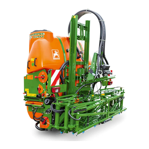
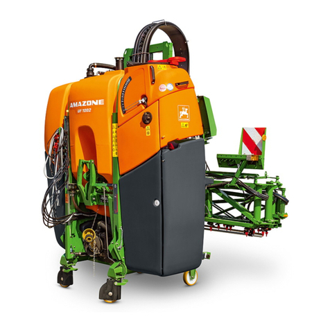
Amazone UF 02 Series User manual

2 ISOBUS field sprayer BAG0171.9 11.20
READING THE
MANUAL
and complying with it should not appear to be in-
convenient and superfluous, as it is not enough to
hear from others and to realize that a machine is
good, to buy it, and to believe that now every-
thing will work by itself. The person concerne
d
would not only harm himself but also make the
mistake of blaming the machine for a possible
failure, instead of blaming himself. To ensure
g
ood success a person, should penetrate into the
spirit of the matter or make himself familiar with
every part of the machine and get acquainte
d
with its handling. Only after this has been done
would the person be satisfied both with the ma-
chine and with himself. To achieve this is the
purpose of this instruction manual.
Leipzig-Plagwitz 1872.

Identification data
ISOBUS field sprayer BAG0171.9 11.20 3
Manufacturer's address
AMAZONEN-WERKE
H. DREYER SE & Co. KG
P.O. Box 51
49202,
Germany
Tel.:
Email:
Hasbergen
+ 49 (0) 5405 50 1-0
Ordering spare parts
Spare parts lists are freely accessible in the Spare Parts Portal at
www.amazone.de.
Please send orders to your AMAZONE dealer.
Formalities of the operating manual
Document number: MG6553
Compilation date: 11.20
Copyright AMAZONEN-WERKE H. DREYER SE & Co. KG, 2020
All rights reserved.
Reprint, even of excerpts, is only possible with the approval of
AMAZONEN-WERKE H. DREYER SE & Co. KG.

Foreword
4 ISOBUS field sprayer BAG0171.9 11.20
Foreword
Dear Customer,
You have chosen one of the quality products from the extensive prod-
uct range of AMAZONEN-WERKE, H. DREYER SE & Co. KG. We
thank you for your trust in our products.
On receiving the implement, check to determine if it has been dam-
aged during transport or if parts are missing! Using the delivery note,
ensure that the implement has been delivered in full, including any
special equipment ordered. Damage can only be rectified if problems
are reported and claims are filed immediately!
Before initial operation, read and comply with the information in this
operating manual, and particularly the safety instructions. Only after
careful reading will you be able to fully benefit from the advantages of
your newly purchased implement.
Please ensure that all the implement operators have read this operat-
ing manual before they place the implement in service.
Should you have any questions or problems, please consult this op-
erating manual or contact your local service partner.
Regular maintenance and timely replacement of worn or damaged
parts increases the service life of your implement.
User evaluation
Dear Reader,
We update our operating manuals regularly. Your suggestions for
improvement help us to create increasingly user-friendly operating
manuals.
AMAZONEN-WERKE
H. DREYER SE & Co. KG
P.O. Box 51
49202,
Germany
Tel.:
Email:
Hasbergen
+ 49 (0) 5405 50 1-0

Contents
I
SOBUS field sprayer BAG0171.9 11.20
5
1User information..........................................................................................7
1.1 Purpose of the document.........................................................................................................7
1.2 Direction information in the operating manual.........................................................................7
1.3 Presentations used ..................................................................................................................7
2General safety notices.................................................................................8
2.1 Presentation of safety symbols................................................................................................8
3Product description.....................................................................................9
3.1 Software version ......................................................................................................................9
3.2 Hierarchy of the ISOBUS software ........................................................................................10
3.3 Field menu / Settings menu...................................................................................................11
4Field menu..................................................................................................12
4.1 Work menu.............................................................................................................................12
4.1.1 Function fields........................................................................................................................13
4.1.2 Displays on the terminal.........................................................................................................15
4.1.3 Procedure in operation...........................................................................................................17
4.2 Mini-view in Section Control...................................................................................................17
4.3 Functions in the Work menu..................................................................................................18
4.3.1 Switch spraying on / off..........................................................................................................18
4.3.2 Switching on Start functions...................................................................................................18
4.3.3 Section control .......................................................................................................................19
4.3.4 Work lights .............................................................................................................................20
4.4 Spray liquid circuit function group ..............................................................................21
4.4.1 Spray quantity control............................................................................................................21
4.4.2 Changing the target rate........................................................................................................21
4.4.3 Switching off the outer part width sections ............................................................................22
4.4.4 Boundary nozzles, end nozzles or extra nozzles...................................................................23
4.4.5 AmaSelect Row .....................................................................................................................23
4.4.6 AmaSelect..............................................................................................................................24
4.4.7 Hydraulic pump drive .............................................................................................................26
4.4.8 Flushing water pump..............................................................................................................26
4.4.9 Front tank with FlowControl...................................................................................................27
4.5 Boom kinematics function group (Profi-folding / Flex-folding)....................................29
4.5.1 Automatic boom ride..............................................................................................................29
4.5.2 Manual boom ride ..................................................................................................................34
4.5.3 Boom folding (Flex-folding)....................................................................................................37
4.5.4 Folding the boom (Profi-folding).............................................................................................40
4.6 Function group boom kinematics (pre-select folding) ................................................43
4.7 Axle function group.....................................................................................................44
4.7.1 AutoTrail steering axle...........................................................................................................44
4.7.2 Hydropneumatic spring suspension.......................................................................................47
4.8 Filling / Refilling menu............................................................................................................48
4.9 Agitation menu.......................................................................................................................50
4.10 Cleaning menu.......................................................................................................................51
4.10.1 Intensive cleaning and quick cleaning ...................................................................................51
4.10.2 Flushing the boom .................................................................................................................52
4.10.3 Diluting...................................................................................................................................52
4.10.4 XtremeClean..........................................................................................................................52
4.11 Documentation menu.............................................................................................................53
4.11.1 Meter readings.......................................................................................................................53

User information
6
ISOBUS field sprayer BAG0171.9
11.20
4.11.2 Weather data......................................................................................................................... 54
5Settings...................................................................................................... 55
5.1 Implement.............................................................................................................................. 56
5.1.1 Speed.................................................................................................................................... 57
5.1.2 Spray liquid circuit................................................................................................................. 59
5.1.3 Hydraulic system................................................................................................................... 63
5.2 Profile .................................................................................................................................... 65
5.2.1 Multi-function display............................................................................................................. 67
5.2.2 Configuring free button assignment...................................................................................... 68
5.2.3 Configuring the start functions .............................................................................................. 68
5.2.4 Configuring the alarm limits................................................................................................... 69
5.2.5 Pump drive ............................................................................................................................ 69
5.2.6 Configuring boom behavior.................................................................................................. 70
5.2.7 Configuring rate control......................................................................................................... 72
5.2.8 Configuring part-width section control................................................................................... 73
5.2.9 Configuring AmaSelect.......................................................................................................... 75
5.2.10 Creating filling profiles........................................................................................................... 86
5.2.11 Configuring ISOBUS ............................................................................................................. 88
5.2.12 Configuring the steering system............................................................................................ 90
5.3 Info......................................................................................................................................... 92
5.4 Setup..................................................................................................................................... 92
6Fault............................................................................................................ 93
6.1 Alarm / warning, and note ..................................................................................................... 93
6.2 Failure of the speed signal from the ISOBUS....................................................................... 93
6.3 Fault table.............................................................................................................................. 94
7AUX-N multi-function sticks................................................................... 113
8AmaPilot+ multi-function stick............................................................... 114
9Boom part width section control box AMACLICK................................ 117
9.1 Function............................................................................................................................... 117
9.2 Attachment .......................................................................................................................... 118

User information
I
SOBUS field sprayer BAG0171.9 11.20
7
1 User information
The User information section provides information concerning the
operating manual.
1.1 Purpose of the document
This operating manual
•describes the operation and maintenance of the implement.
•provides important information on safe and efficient handling of
the implement.
•
is a component part of the implement and should always be kept
with the implement or in the towing vehicle.
•must be kept in a safe place for future use.
1.2 Direction information in the operating manual
All the direction information in the operating manual is always as
viewed in the direction of travel.
1.3 Presentations used
Instructions and responses
Activities to be carried out by the user are presented as numbered
instructions. Always follow the sequence of the numbered instruc-
tions. The implement response to the respective instruction may pos-
sibly be marked with an arrow.
Example:
1. Instruction 1
→Implement response to instruction 1
2. Instruction 2
Listings
Listings without a mandatory order are shown as a list with bullets.
Example:
•Point 1
•Point 2
Item numbers in illustrations
Numbers in round brackets refer to the item numbers in the illustra-
tions. Example:
(1) Item 1

General safety notices
8
ISOBUS field sprayer BAG0171.9
11.20
2 General safety notices
Knowledge of the basic safety notices and safety regulations is a fun-
damental requirement for safe handling and fault-free implement op-
eration.
The operating manual
•must always be kept at the place where the implement is oper-
ated!
•must always be easily accessible for the user and maintenance
personnel!
2.1 Presentation of safety symbols
Safety notices are indicated by the triangular safety symbol and the
highlighted signal word. The signal word (DANGER, WARNING,
CAUTION) describes the severity of the risk, and has the following
meaning:
DANGER
Indicates a direct hazard with high risk that will result in death or
serious injury (loss of limbs or long-term harm), if not avoided.
Failure to comply with these notices will result in death or seri-
ous injury.
WARNING
Indicates a possible hazard with moderate risk that can result in
death or (serious) injury if not avoided.
Failure to comply with these notices may result in death or seri-
ous injury.
CAUTION
Indicates a hazard with low risk that can result in minor or mod-
erate injury or material damage, if not avoided.
IMPORTANT
Indicates an obligation to behave in a particular manner or indi-
cates an activity required for proper handling of the machine.
Failure to comply with these notices can cause faults on the im-
plement or damage in the vicinity of the implement.
NOTE
Indicates handling tips and particularly useful information.
These notes will help you to use all the functions of your ma-
chine in the best manner possible.

Product description
I
SOBUS field sprayer BAG0171.9 11.20
9
3 Product description
The ISOBUS software and an ISOBUS terminal make it easy to con-
trol, operate, and monitor the AMAZONE implements.
The ISOBUS software works with the following AMAZONE imple-
ments:
•UX 4201, UX 5201, UX 6201, UX11201
•UF 1002, UF 1302, UF 1602, UF 2002
•Pantera 4503, Pantera 4504
During operation
•the Work menu shows all work data,
•the implement is operated via the Work menu,
•the ISOBUS software regulates the spread rate depending on
the forward speed.
3.1 Software version
This operating manual is valid from software version:
ISOBUS job computer
NW242-F
(AEL652)

Product description
10
ISOBUS field sprayer BAG0171.9
11.20
3.2 Hierarchy of the ISOBUS software
Settings
Field menu
Documentation
Implement menu
Speed
Spray liquid circuit
Hydraulic system
Work
Filling
Cleaning
Agitation
Profile menu
Multi-function display
Free button assignment
Start function
Alarm limits
Pump drive
Boom behavior
Rate control
Part-width section control
AmaSelect
Filling profiles
ISOBUS
Steering
Info menu
·Back to the previous menu
Scroll through the screens in the menu

Product description
I
SOBUS field sprayer BAG0171.9 11.20
11
3.3 Field menu / Settings menu
The Field menu is active after switching on the terminal.
Go to the Field menu.
Go to the Settings menu.
→The selected symbol is displayed in color.
Field menu for operating the implement:
Settings menu for settings and management:
Field menu
Settings
Work
Filling
Implement
Profile
Cleaning
Info
Documen
tation
Agitation
Profile 1
200
l/ha

Field menu
12
ISOBUS field sprayer BAG0171.9
11.20
4 Field menu
•Work menu
Operating the implement on the field
•Filling menu
•Cleaning menu
•Documentation of jobs menu
•Agitation menu
Work
Filling
Cleaning
Documenta-
tion
Agitation
→The currently selected profile is
displayed.
→The desired target quantity can be
entered here
Profile 1
21,39
gal/ac
200
l/ha
4.1 Work menu
The implement is operated via the Work menu with its sub-menus.
The sub-menus are divided into function groups.Depending on the
type and equipment of the machine, some functions of the Work
menu and sub-menus may not be available.
Display area
Function fields for operation

Field menu
I
SOBUS field sprayer BAG0171.9 11.20
13
4.1.1 Function fields
The function fields are distributed across several pages in the Work
menu.
Each function field can be assigned with any desired function by
changing the button assignment.
Scroll to find the function fields
There are 2 types of function fields:
(1) Direct call-up of the functions
For example:
οSpraying on/off
οSection Control automatic / manual
(2) Call-up of function groups.
Function groups are marked by a triangle at the top right.
οBoom kinematics
οSpraying
οAxle
•Under the function groups, there are other function fields for
calling up functions directly.
•The functions of the function groups can also be placed outside
of the function group by changing the button assignment.
•
The functions of the function groups are likewise distributed over
several pages.

Field menu
14
ISOBUS field sprayer BAG0171.9
11.20
•Scroll if necessary.
•Exit the function group.
Executing functions via function fields
Touch to execute functions.
Touching a button executes the function.
•Switch on and off
•Select alternatives
•Navigate
Press and hold to execute functions.
Press and hold the function field until the desired end position is
reached.

Field menu
I
SOBUS field sprayer BAG0171.9 11.20
15
4.1.2 Displays on the terminal
4 fields for selectable multi-function
displays
264 gal / 999
l /ha
Actual qty
Fill level
100 %
Actual quantity in %
1611 gal / 6100 l
125 psi / 8.6 bar
Spray pressure
Section Control mode
Part-width section control:
Spraying: Part-width sections
switched on (green)
Spraying: Part-width sections
switched off
1 2 3 4 5 6 7
Number of part-width sections
Single nozzle control:
Spraying: Nozzles switched on
(green)
Spraying: Nozzles switched off
Sprayers with CurveControl (rate
adjustment when driving in
curves)
AmaSelect band spraying row
Area spraying
Edge nozzles
Band spraying
Steering
Boom guidance
Operating displays:
(1) Lighting
(2) Spraying pump
(3) Hydraulic preselect folding
(4) Active function of the hydraulic
pre-select folding
(5) AmaSelect: active nozzle and
automatic/manual mode
(1)
(2)
(3)
(4)
(5)

Field menu
16
ISOBUS field sprayer BAG0171.9
11.20
Automatic mode for various functions
Automatic mode on
Automatic mode off / manual operation
Scroll through the operating pages in the Work menu.
The exclamation point indicates a special situation or a fault!

Field menu
I
SOBUS field sprayer BAG0171.9 11.20
17
4.1.3 Procedure in operation
1. Select the Work menu on the control terminal.
2. Oil circulation: Supply the hydraulic block with oil via the red
tractor control unit.
3. Fold-out the sprayer boom.
4. Adjust the boom height and align the boom.
5. UX with steering axle: AutoTrail on automatic mode.
6. Boom ride on automatic mode.
7. Switch on Section Control if necessary.
8. Switch on the sprayer, start moving the tractor and spray the
area.
9. Switch off spraying.
10. Clean the sprayer (Comfort Package: Use the cleaning program)
11. Fold-in the sprayer boom.
12. Lock the steering axle in the center position.
13. Oil circulation: Interrupt oil supply.
4.2 Mini-view in Section Control
Mini-view is a section of the Work menu that is
shown in the Section Control menu.
(1) The first 2 lines of the multi-function display
and spray pressure
(2) Boom ride
(3) AutoTrail
(4) Actual value and setpoint adaptation
Notes are also shown in the Mini-views.
(1)
(2)
(3)
(4)

Field menu
18
ISOBUS field sprayer BAG0171.9
11.20
4.3 Functions in the Work menu
4.3.1 Switch spraying on / off
Switch spraying on / switch spraying off
•Switch spraying on: Spray fluid is applied
via the spraying nozzles.
•Switch spraying off: No spray liquid is ap-
plied.
Display in the Work menu:
Spraying switched on
Spraying switched off
4.3.2 Switching on Start functions
Switching on the start functions collectively
Depending on the selected configuration, the
following automatic process functions can be
switched on simultaneously:
(1) Section Control
(2) Unlock the boom, boom ride
(3) AutoTrail
(4) Hydropneumatic spring suspension
(5) AmaSelect
(6) FlowControl
(7) Hydraulic pump drive
It is not possible to switch off the automated pro-
cesses collectively.
Not all of the automatic functions are shown in
the Work menu.

Field menu
I
SOBUS field sprayer BAG0171.9 11.20
19
4.3.3 Section control
Switching Section Control on and off on the implement
The terminal must be equipped with Section Control. Section Control
must be switched on via the terminal application.
→In this case Section Control can be switched via the
ISOBUS software.
Conditions for Section Control:
•Section Control must be switched on via the terminal.
•Implement must be in working position (only Profi-folding)
1. Switch on Section Control.
2. Switch on the implement.
→Spraying starts when the implement starts
moving, i. e. when the implement is in work-
ing position and is switched on.
Section Control active:
→
All conditions for Section Control have been
met.
No Section Control:
→Section Control is signed onto the terminal,
but it is not switched on.
→The conditions for Section Control have not
been met.
No Section Control:
→Section Control is signed onto the terminal.
→The conditions for Section Control have
been met.
→Section Control does not start through the
implement software.
Section Control must be switched
on.

Field menu
20
ISOBUS field sprayer BAG0171.9
11.20
Spraying off:
(1) Part width section switched off
manually (red)
(2) Part-width section (Section Control)
(3) Spraying not switched on (gray)
Spraying on:
(4) Spraying (green)
(1) (2) (3) (4)
If automatic part width section control is not pos-
sible, a note appears with the required condi-
tions.
•Condition not fulfilled
•Condition fulfilled
Section Control cannot
be activated!
The following conditions must
be fulfilled:
Section Control of the terminal
(Task Controller) must be activated
Implement must be free of errors
Booms must be in working condition
Please confirm
Environmental pollution due to undesired application of spray
agents.
Use of Section Control is only permitted within the defined field
boundaries.
4.3.4 Work lights
Switching the work lights on / off
Alternatively, switch the work lights via TECU
(depending on the configuration).
The work lights are automatically switched off for
road travel via the drive speed.
Display work lights switched on →
This manual suits for next models
12
Table of contents
Other Amazone Paint Sprayer manuals