manuals.online logo
Brands
  1. Home
  2. •
  3. Brands
  4. •
  5. American Dynamics
  6. •
  7. Security Camera
  8. •
  9. American Dynamics ADCDH User manual

American Dynamics ADCDH User manual

Regulatory Compliance
Emissions FCC part 15 Class B
CE: EN55011
ICES-003
EN55022
CISPR 11
CISPR22
ANSI C63.4
Immunity CE: EN50130-4
Safety CSA C22.2
UL60065
FCC COMPLIANCE: This equipment complies with Part 15 of the FCC rules for intentional radiators and Class B digital
devices when installed and used in accordance with the instruction manual. Following these rules provides reasonable pro-
tection against harmful interference from equipment operated in a commercial area. This equipment should not be installed
in a residential area as it can radiate radio frequency energy that could interfere with radio communications, a situation the
user would have to x at their own expense.
CISPR 22 WARNING: This is a Class B product. In a domestic environment this product may cause radio interference in
which case the user may be required to take adequate measures.
POWER SUPPLY REQUIREMENTS: For use with listed Audio/Video Product and only connected to 15W or less power sup-
ply. Power supply should be a NEC Class 2 / LPS Supply.
EQUIPMENT MODIFICATION CAUTION: Equipment changes or modications not expressly approved by Sensormatic
Electronics Corporation, the party responsible for FCC compliance, could void the user’s authority to operate the equipment
and could create a hazardous condition.
RLJ 02/2005
Please visit our website for more information
www.americandynamics.net
© 2005 Sensormatic Electronics Corporation
Product specications subject to change without notice.
Certain product names mentioned herein may be trade names and/or registered trademarks of other companies.
8200-0206-28 Rev E
N.SVR
ALCV-PHASE
L–
H+
ON
AWBAWB.EX
INTLL
FL
ON
BLC ON
AGCEX
A ADCDS
A1: Focus adjuster
A2: Field of view adjuster
A1
A2
Camera adjustments for the ADCDH series
DIP switch settings
The bank of dip switches allow the following settings to be made:
Night-Saver mode (N.SVR / ON)
When ON the camera operates in monochrome mode in reduced lighting.
Auto White Balance (AWB / AWB.EX)
AWB: The camera operates in the normal Auto White Balance range 2700K~11000K.
AWB EX: The camera runs in the extended Auto White Balance range 2000K~18000K.
Line Lock (INT / LL)
In LL mode the V-Phase may be adjusted to compensate for connected supply phase differences.
Only applicable for 24VAC supply – otherwise the camera operates with INTernal sync.
Flickerless mode (FL / ON)
ON: The Camera reduces icker in the image under uorescent lighting.
Back Light Compensation (BLC)
When set ON, this option improves the camera response to strong, unwanted lighting effects
behind the required subject.
Low light sensitivity (AGC-EX)
When set to EX sensitivity in low light is increased.
Focus & eld of view adjustment
Twist the levers on the side of the varifocal camera to adjust the focus and eld of view settings.
TIP: If necessary, perform the nal focus through the dome cover, holding it to the lens reversed
to conrm the nal results.
Vertical phase adjustment
Use this adjustment when using an AC supply to align the camera phase with that of the supply.
Iris adjustment
This is factory set and should not normally require adjustment except to compensate for
excessive image blooming.
B ADCDH
N.SVR
ALC V-PHASE
L–
H+
ON
AWBAWB.EX
INT LL
FL
ON
BLC ON
AGC EX
B1
B2
B3
B5
B4
B1: Focus adjuster
B2: Field of view adjuster
B3: DIP switches
B4: ALC adjustment
B5: V-PHASE adjustment
Camera adjustments
Type / Format NTSC PAL
Scanning Element 2:1 Interlace, 2:1 Interlace,
H15.750KHz / V :59.94Hz H15.625KHz / V :50Hz
Image Picture Element 1/3” Interline CCD
Effective Picture Element 768(H) x 494(V) 752(H) x 582(V)
Approximate pixels 380K 430K
Resolution (TV lines) 540 (normal)
Minimum Illumination 0.65 Lux @ F1.2
S/N Ratio 50dB
AGC.EX Gain 30dB
AGC Preset Gain 26dB
Back Light Compensation Central area for auto iris
Exposure Control DC Auto IRIS Drive
Sync System Internal/Line lock
Line Lock (Phase Adj. Range) 0o~270o
Line Lock (Frequency Range) 60Hz ±1Hz 50Hz ±1Hz
Gamma Compensation 0.45
Video Output 1.0Vpp, 75 ohm Unbalanced
White Balance Automatic White Balance
AWB Normal Range 2700K – 11000K
AWB.EX Range 2000K – 18000K
Power Range AC: 24VAC ±20% or DC: 12VDC -10% +12%
Power Consumption 2.8W (Max)
Operating Temperature -30oC to +50oC
Storage Temperature -35oC to +60oC
ADCDH camera specications
Type / Format NTSC PAL
Scanning Element 2:1 Interlace, 2:1 Interlace,
H15.734KHz / V :59.94Hz H15.625KHz / V :50Hz
Image Picture Element 1/3” Interline CCD
Effective Picture Element 510(H) x 492(V) 500(H) x 582(V)
Approximate pixels 380K 430K
Resolution (TV lines) 330
Minimum Illumination 0.7 Lux @ F1.2
S/N Ratio 48dB
Exposure Control DC Auto IRIS
Sync System Internal
Gamma Compensation 0.45
Video Output 1.0Vpp, 75 ohm Unbalanced
White Balance Automatic White Balance
Auto White Balance Range 2700K – 11000K
Power Range AC: 24VAC ±20% or DC: 12VDC -10% +12%
Power Consumption 1.7W (Max)
Operating Temperature -30oC to +50oC
Storage Temperature -35oC to +60oC
ADCDS camera specications
ADCDS
Standard Resolution
330TVL
Image Picture Element Pixim Orca Sensor
Effective Picture Element 720(H) x 540(V)
Resolution (TV lines) 540
Minimum Illumination 0.95 Lux @ F1.2 (AGC Boost)
S/N Ratio >42dB
Wide Dynamic Range 120 dB / 17bit
Wide Dynamic Range Area 1 Zone - Fully Adjustable
Slow Shutter Default 2x, max 32x
Electronic Shutter 1/50 or 1/60 ~ 1/100000
Day/Night Night Saver Auto/On/Off
White Balance ATW, MWB, 1-Touch
Auto White Balance Range 2200oK ~ 7500oK, 2000oK ~ 11000oK
Sync System Internal/Line lock
57Hz - 62.4Hz for NTSC
47.5Hz - 52Hz for PAL
Video Output 1.0Vpp, 75 ohm Unbalanced
Power Range AC: 24VAC ±20% or DC: 12VDC -10% +12%
Power Consumption 3W (Max)
Operating Temperature -30oC to +50oC
Storage Temperature -35oC to +60oC
ADCDW camera specications
ADCDH
High Resolution
540TVL
ADCDW
High Resolution
Wide Dynamic Range 540TVL
DISCOVER MINI-DOME
Camera Sheet
Focal Length 2.5~6.0mm 3.8~9.5mm 9~22mm
F-No. F1.3 F1.2 F1.8
Iris Range F1.3~F360 F1.2~F360 F1.8~F360
Minimum Object Distance 0.15mm (6”) 0.15mm (6”) 0.2mm (8”)
Field Of View Diagonal 136.6º~59.4º 96.8º~37.4º 39.0º~17.6º
Horizontal 108.2º~47.6º 74.2º~30.0º 30.7º~14.1º
Vertical 80.4º~35.6º 54.0º~22.4º 22.7º~10.6º
Lens Type Aspherical Aspherical Spherical
IR Corrective Coating Yes Yes No
Lens specications (for all camera models)
VIDEO STANDARD Select the video standard the camera should use - NTSC or PAL. (NOTE - If the camera is "Restored to Factory Settings" it will default to
NTSC. This is due to it being dual standard.)
WDR PRESETS - These are "factory set" general configurations. Select the preconfigured WDR mode for the camera to use to give the best performance for
the specied environment. Pressing the ENTER key on the selected option will display the pre-congured set-up parameters. If adjustment is
necessary please go to the "WDR METERING ADJUST" zone in the "GLOBAL CAM SETTINGS" menu.
NORMAL - This should provide the most versatile settings for general purpose applications.
INDOOR or OUTDOOR - These settings are optimized for indoor / outdoor lighting conditions.
CUSTOM - Please refer to WWW.AMERICANDYNAMICS.NET for settings for this menu structure.
GLOBAL CAM SETTINGS: This page contains the standard adjustments needed for camera operation and applies to all WDR preset modes.
SYNC: Select Synchronization mode:
INT - Internally generated sync.
INT FL - Internal Flickerless - Internally generated sync that can reduce icker under orescent lighting
LL: - Line Lock - Sync is locked to the AC supply cycle and permits adjustment of V-phase to correct for vertical sync picture roll. (Applicable
for 24VAC supply only. If a 12 volt DC power supply is used the camera will run in INT or INT FL modes only)
WB MODE: ATW DESAT - When the camera is operating outside its pre-programmed White Balance Range, the chroma content is reduced, to give the resultant
image a more natural look. If necessary, the range is congurable with low limit (to help with reds) and high limit (to help with blues) adjustments.
TOUCH - Pressing the enter key sets & xes the White Balance according to current image content. Once set the white balance will not auto
adjust anymore. This is good for static environment applications where the lighting conditions never change, like indoor hallways.
MANUAL (White Balance):-
ADJ MODE - allows manual setting of the colour temperature of the image. This can be achieved by using the Kelvin or Red/Blue option and
permits two methods of setting color balance, by which ever method the installer is familiar with. This setting is also good for static environ-
ment applications where the lighting conditions never change, like indoor hallways
ATW Xtnd - extended Auto White Balance range - use this setting for scenes that may have an extremely wide range of color temperature.
ATW Normal - selects a normal Auto White Balance range, for general operation. If necessary the range is congurable with low limit (to help
with reds) and high limit (to help with blues) adjustments.
DC LENS LEVEL - This is to adjust the iris on a DC auto iris lens and is factory set. It should not need adjustment under normal operation.
DVR SAVER - When ON, The DVR-Saver mode feature may be used to reduce storage requirements when connected to a digital video recorder. This feature can
also be used to reduce bandwidth requirements when connected to a digital network via an encoder. Note the images may appear slightly "softer" but this
will have negligible effect once compressed in the DVR. When Off – Normal operation
NIGHT SVR CONTROL - Day / Night (Color / Monochrome) operation. This feature may be used to improve low light performance by reducing noise from the
video signal. AUTO MODE - In reduced lighting camera switches automatically to Night (black and white) mode and back to Color once the ambient lighting
comes back to normal levels. OFF Forces the camera into Day (Color) only mode regardless of lighting conditions. ON Force the camera into Night (BW) only
mode regardless of lighting conditions.
WDR METERING ADJ – This feature is used to congure the area used for WDR light metering - Tapping the ENTER key reveals a box which is the WDR zone.
Repeatedly tapping the ENTER key changes the color of the zone. White – Move entire zone’s position. Green – Used to increase the size of the zone. Red
– Used to reduce the size of the zone. Use the arrow keys to adjust the zone position or size. Holding the [ENTER] key for 3 seconds returns you to the previ-
ous menu. The default setting will provide good general performance. If adjustment is necessary, size according to the area of interest making sure to include
all areas of interest. This will dictate how the overall wide dynamic range features operate. Example: An internal scene viewing a doorway and polished oor.
Daylight often streams though the doorway. It is required to see people entering the doorway and follow them to the left
hand side of the picture. The door way is central to the image. The box should be sized and postioned to cover the doorway
and the area to the left where people walk.
PICTURE ADJ. - BRIGHTNESS - Adjusts overall image brightness.
SHARPNESS – Adjusts overall image sharpness.
FLICKERLESS - Used to help reduce flicker or color rolling under florescent lighting.
FL1 - Standard Setting - *Line Lock sync recommended* (To use Line Lock with FL1 a 24VAC power supply must be used.)
FL2 – NTSC/50Hz Setting - Select to overcome icker in a 50Hz NTSC Environment. Must turn on of off via sub-menu.
GAMMA MODE: Select appropriate gamma mode for type of display. Gamma Correction compensates for a non linear grayscale in a display device or to make
non standard luminance.
AUTO - Standard for a CRT based monitor.
LCD – Optimized for LCD monitors. Also has adjustment sub-menu for ne manual control which will display "manual" if set and saved
MANUAL Manual Gamma may be used to enhance detail in low light areas of an image which would normally not be visible with highlights present in the
image.
COLOR SATURATION - Adjusts overall color content of the image.
RESTORE SETTINGS – This will undo any changes made since the last "Save Settings"
SAVE SETTINGS - Save any programming changes to ensure they are retained after power loss or reset. If changes are not saved, the camera will revert to the
previous settings on power-up.
RESTORE FACTORY SETTINGS - Restore camera settings to factory default - full reset, all previous programming will be lost including video standard which will
default to NTSC.
RESET CAMERA - This is a soft reset and has the same effect as cycling the camera power.
SYSTEM INFO - Displays the camera firmware version - This may be required during any call to American Dynamics Technical Support.
ADVANCED CAMERA SETTINGS - please refer to WWW.AMERICANDYNAMICS.NET for settings for this menu structure.
RESTORE SETTINGS – This will undo any changes made since the last "Save Settings"
SAVE SETTINGS - Save any programming changes to ensure they are retained after power loss or reset. If changes are not saved, the camera will revert to the
previous settings on power-up
RESTORE FACTORY SETTINGS - Restore camera settings to factory default - full reset, all previous programming will be lost including video standard which will
default to NTSC.
RESET CAMERA - This is a soft reset and has the same effect as cycling the camera power.
SYSTEM INFO - Displays the camera firmware version - This may be required during any call to American Dynamics Technical Support.
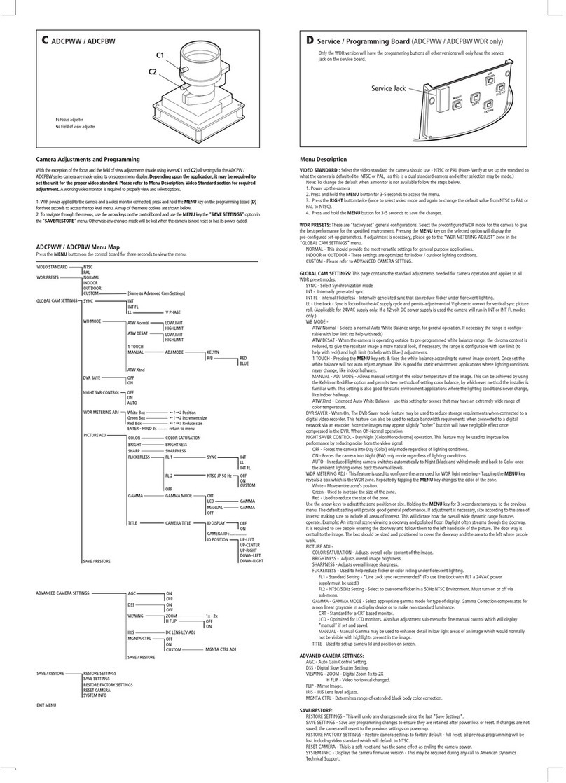
Camera adjustments and programming for the ADCDW series
With the exception of the focus and eld of view adjustments (made using levers C1 and C2) all
settings for the ADCDW series camera are made using its on screen menu display. A working video
monitor and a separate plug-in control board (C3) are required to view and select options.
1 Within the dome enclosure, attach the control board connector to the socket (C4) at the top of
the service jack interface board. Ensure that the OSD lead (C6) is connected between the middle
socket of the smaller circuit board and the camera.
2 With power applied to the camera and a video monitor connected, press and hold the ENTER key
for three seconds to access the top level menu. A map of the menu options are shown below.
3 To navigate through the menus, use the arrow keys on the control board and use the ENTER key
to select the required menu eld.
IMPORTANT: When you make changes to the camera conguration, you MUST save them using
the “SAVE SETTINGS” option in the “SAVE/RESTORE” menu. Otherwise any changes made will
be lost when the camera is next reset or has its power cycled.
VIDEO STANDARD NTSC
PAL
WDR PRESTS NORMAL
INDOOR
OUTDOOR
CUSTOM [Same as Advanced Cam Settings]
GLOBAL CAM SETTINGS SYNC INT
INT FL
LL V PHASE 0~624
PREVIOUS PAGE
WB MODE ATW DESAT LOWLIMIT 2K~5.5K
HIGHLIMIT 5.5K~11K
PREVIOUS PAGE
TOUCH
MANUAL ADJ MODE KELVIN 2K~11K
PREVIOUS PAGE
R/B RED -20~20
BLUE -20~20
PREVIOUS PAGE
PREVIOUS PAGE
ATW Xtnd
ATW Normal LOWLIMIT 2K~5.5K
HIGHLIMIT 5.5K~11K
PREVIOUS PAGE
DC LENS LEVEL H~L
DVR SAVE OFF
ON
NIGHT SVR CONTROL AUTO
OFF
ON
WDR METERING ADJ [enter] White Box  Position
Green Box  Increment size
Red Box  Reduce size
ENTER - HOLD 3s return to menu
PICTURE ADJ BRIGHTNESS 80~150
PREVIOUS PAGE
SHARPNESS -8~+8
PREVIOUS PAGE
FLICKERLESS FL 1 SYNC INT
LL 0~624
RETURN
FL 2 NTSC JP 50 Hz OFF
ON
RETURN
OFF
GAMMA GAMMA MODE AUTO
LCD 25~100
PREVIOUS PAGE
MANUAL 25~100
PREVIOUS PAGE
OFF
PREVIOUS PAGE
COLOR COLOR SATURATION -8~+8
PREVIOUS PAGE
SAVE / RESTORE RESTORE SETTINGS
SAVE SETTINGS
RESTORE FACTORY SETTINGS
RESET CAMERA
SYSTEM INFO FW Rev
PREVIOUS PAGE PREVIOUS PAGE PREVIOUS PAGE
ADVANCED CAMERA SETTINGS
SAVE / RESTORE RESTORE SETTINGS
SAVE SETTINGS
RESTORE FACTORY SETTINGS
RESET CAMERA
SYSTEM INFO FW Rev
EXIT MENU PREVIOUS PAGE
C ADCDW
C1: Focus adjuster
C2: Field of view adjuster
C1
C2
Menu Description
ADCDW Menu Map
Press the ENTER button on the control board for three seconds to view the menu.
WDR ZONE
ENTER RIGHT
DOWN
OSD CONTROL BOARD
LEFT
UP
C3
C4
C3: Control board (ADCDW camera only)
C4: Control board connector on service jack circuit board
C5: Main lead to camera
C6: OSD lead to camera (ADCDW camera only)
C6
C5

This manual suits for next models

2

Other American Dynamics Security Camera manuals

American Dynamics IP speedDome Ultra 8 User manual

American Dynamics

American Dynamics IP speedDome Ultra 8 User manual

American Dynamics SpeedDome Ultra VIIE User manual

American Dynamics

American Dynamics SpeedDome Ultra VIIE User manual

American Dynamics Tyco Discover Series User manual

American Dynamics

American Dynamics Tyco Discover Series User manual

American Dynamics RASIPPS-1 User manual

American Dynamics

American Dynamics RASIPPS-1 User manual

American Dynamics SpeedDome Optima LT Manual

American Dynamics

American Dynamics SpeedDome Optima LT Manual

American Dynamics ADC722WP User manual

American Dynamics

American Dynamics ADC722WP User manual

American Dynamics ADC860 User manual

American Dynamics

American Dynamics ADC860 User manual

American Dynamics Illustra 625 PTZ User manual

American Dynamics

American Dynamics Illustra 625 PTZ User manual

American Dynamics SpeedDome Optima User manual

American Dynamics

American Dynamics SpeedDome Optima User manual

American Dynamics ADCSHR2412N User manual

American Dynamics

American Dynamics ADCSHR2412N User manual

American Dynamics Illustra Flex Series User manual

American Dynamics

American Dynamics Illustra Flex Series User manual

American Dynamics ADC660 User manual

American Dynamics

American Dynamics ADC660 User manual

American Dynamics RASO series User manual

American Dynamics

American Dynamics RASO series User manual

American Dynamics ADCI625-P221 User manual

American Dynamics

American Dynamics ADCI625-P221 User manual

American Dynamics ADSDUHOC User manual

American Dynamics

American Dynamics ADSDUHOC User manual

American Dynamics SensorRail IIIe ADRL3TRK Series User manual

American Dynamics

American Dynamics SensorRail IIIe ADRL3TRK Series User manual

American Dynamics ADC733 User manual

American Dynamics

American Dynamics ADC733 User manual

American Dynamics AD615 User manual

American Dynamics

American Dynamics AD615 User manual

American Dynamics SpeedDome Ultra Manual

American Dynamics

American Dynamics SpeedDome Ultra Manual

American Dynamics ADC722WP User manual

American Dynamics

American Dynamics ADC722WP User manual

American Dynamics ADC710 User manual

American Dynamics

American Dynamics ADC710 User manual

American Dynamics ADCIPE3312ISN User manual

American Dynamics

American Dynamics ADCIPE3312ISN User manual

American Dynamics Illustra 1MP User manual

American Dynamics

American Dynamics Illustra 1MP User manual

American Dynamics ADC520D User manual

American Dynamics

American Dynamics ADC520D User manual

Popular Security Camera manuals by other brands

Ameba SD-436R user manual

Ameba

Ameba SD-436R user manual

Honeywell HD2FC1X instruction manual

Honeywell

Honeywell HD2FC1X instruction manual

Eneo ICB-62M2712M5A user manual

Eneo

Eneo ICB-62M2712M5A user manual

Wyze Cam Pan quick start guide

Wyze

Wyze Cam Pan quick start guide

Spyclops SPY-MINIBULLETG user guide

Spyclops

Spyclops SPY-MINIBULLETG user guide

USA SSC KS series user manual

USA SSC

USA SSC KS series user manual

Vivotek IP7133 Specifications

Vivotek

Vivotek IP7133 Specifications

Evertech EV-CHDBLB user manual

Evertech

Evertech EV-CHDBLB user manual

Messoa NDR721 user manual

Messoa

Messoa NDR721 user manual

Asoni CAM419 user manual

Asoni

Asoni CAM419 user manual

D-Link DCS-930L user manual

D-Link

D-Link DCS-930L user manual

Speco CVC-625WP Specifications

Speco

Speco CVC-625WP Specifications

Siqura FD2005M1-EI quick start guide

Siqura

Siqura FD2005M1-EI quick start guide

Vivotek SUPREME IP9172-LPC user manual

Vivotek

Vivotek SUPREME IP9172-LPC user manual

Vista VK2 Series installation manual

Vista

Vista VK2 Series installation manual

Axis P3904-R Mk user manual

Axis

Axis P3904-R Mk user manual

D-Link SECURICAM DCS-6511 Quick installation guide

D-Link

D-Link SECURICAM DCS-6511 Quick installation guide

Speco VLEDB2HW manual

Speco

Speco VLEDB2HW manual

manuals.online logo
manuals.online logoBrands
  • About & Mission
  • Contact us
  • Privacy Policy
  • Terms and Conditions

Copyright 2025 Manuals.Online. All Rights Reserved.