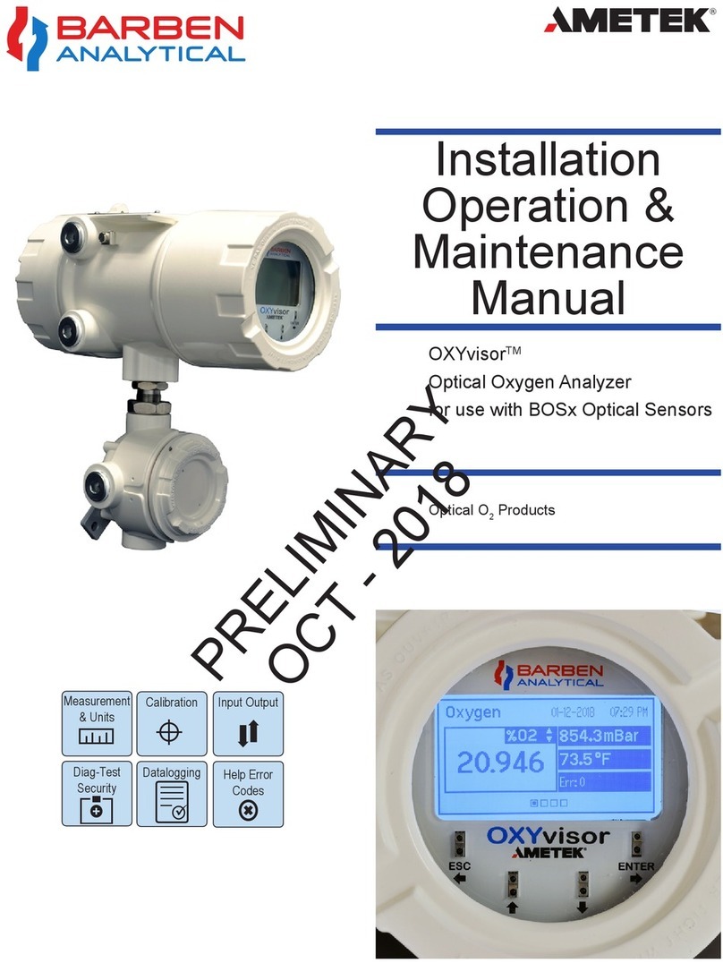
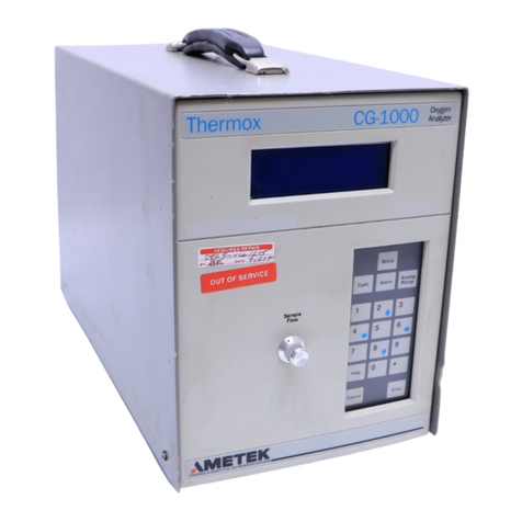
Ametek Dycor CG1100 Series User manual

Dycor CG1100 Oxygen Analyzer
User Manual
PN 90484VE, Rev. J
Process Instruments
150 Freeport Road
Pittsburgh, PA 15238

ii | Dycor CG1100 OxygenAnalyzer
© 2000 AMETEK
This manual is a guide for the use of the Dycor CG1100 Oxygen Analyzer. Data herein has been veried and validated and is believed adequate for the
intended use of this instrument. If the instrument or procedures are used for purposes over and above the capabilities specied herein, conrmation of
their validity and suitability should be obtained; otherwise, AMETEK does not guarantee results and assumes no obligation or liability. This publication
is not a license to operate under, or a recommendation to infringe upon, any process patents.
Ofces
USA - Pittsburgh
150 Freeport Road
Pittsburgh, PA 15238
Ph. 412-828-9040
Fax 412-826-0399
CHINA
AMETEK Shanghai (SPL)
Room 408, Metro Tower
#30 Tian Yao Qiao Road
Shanghai 200030
Ph. 86 21 6426 8111
Fax 86 21 6426 7054
USA - Delaware
455 Corporate Blvd.
Newark, DE 19702
Ph. 302-456-4400
Fax 302-456-4444
AMETEK Beijing
CITIC Building, Room 2305
19, Jianguomenwai Dajie
Beijing 100004
Ph. 86 10 8526 2111
Fax 86 10 8526 2141
USA - Texas
4903 West Sam Houston Parkway North
Suite A-400
Houston, TX 77041
Ph. 713-466-4900
Fax 713-849-1924
FRANCE
AMETEK Precision Instruments France
Rond Point de l’épine des champs
Buroplus Bat D
78990 Elanbourt
Ph. 33 1 30 68 89 20
Fax 33 1 30 68 89 29
CANADA
2876 Sunridge Way N.E.
Calgary, AB T1Y 7H9
Ph. 403-235-8400
Fax 403-248-3550
GERMANY
AMETEK GmbH
Rudolf-Diesel-Strasse 16
D-40670 Meerbusch
Ph. 49 21 59 91 36 0
Fax 49 21 59 91 3680
MIDDLE EAST – Dubai
AMETEK
PO Box 17067
Jebel Ali Free Zone
Dubai, UAE
Ph. 971-4-881 2052
Fax 971-4-881 2053

| iii
Contents
Offices ......................................................................................................................ii
Safety Notes .......................................................................................................... vi
Electrical Safety..................................................................................................... vi
Grounding............................................................................................................. vi
Warning Labels.................................................................................................... vii
Environmental Information (WEEE) ............................................................... vii
Electromagnetic Compatibility (EMC)............................................................ viii
European Standards Information ......................................................................ix
CHAPTER 1 CG1100 Oxygen Analyzer
Overview............................................................................................................. 1-1
Controller / Communications.................................................................... 1-1
Sensor Operations.............................................................................................. 1-2
EMS Grounding, Shielding, and Noise Protection....................................... 1-4
Transient and RFI Interference ........................................................................ 1-5
Technical Support............................................................................................... 1-6
CHAPTER 2 Specications
CHAPTER 3 Installation
Mechanical Installation ..................................................................................... 3-3
Analyzer Description......................................................................................... 3-4
Sample Gas Flow................................................................................................ 3-7
Sample Gas Requirements......................................................................... 3-7
Sample Gas Set Up Connections............................................................... 3-7
Calibration Gas Requirements .................................................................. 3-8
Mechanical Flow Meter.............................................................................. 3-8
Calibration Gas Set-Up............................................................................... 3-9
PPM Measurement Suggestions.................................................................... 3-10
Installation of Electrical Components........................................................... 3-11
Electrical Installation................................................................................. 3-11
Wiring Verification .................................................................................... 3-11
RS-232 Adaptor Cable............................................................................... 3-16
Alarm Contact Connections .................................................................... 3-17
Output Wiring ........................................................................................... 3-18
Analog/Digital and I/O Pinout Reference.............................................. 3-18
Status LEDs and Alarms........................................................................... 3-19
Connect the CG1100 to the Line Power................................................. 3-20

iv | Dycor CG1100 OxygenAnalyzer
CHAPTER 4 Controller / User Interface
System Start-Up.................................................................................................. 4-1
Setting up System Parameters................................................................... 4-1
PC Requirements for Configurator Software ......................................... 4-1
Configurator Software Installation........................................................... 4-2
Configuring Your Device .................................................................................. 4-3
General Tab................................................................................................... 4-3
Device Communications Tab..................................................................... 4-5
Setup Tab....................................................................................................... 4-6
Alarm Tab...................................................................................................... 4-7
Analog Tab .................................................................................................... 4-8
Calibration Tab............................................................................................. 4-9
Verification Tab........................................................................................... 4-10
CHAPTER 5 Calibrating the CG1100-RTP
Calibration........................................................................................................... 5-1
Aborting a Calibration....................................................................................... 5-1
CHAPTER 6 Diagnostic Checks and Troubleshooting
Diagnostics Checks ............................................................................................ 6-1
Wiring Checks..................................................................................................... 6-2
Wiring Problem............................................................................................ 6-2
Analog Board Connections...................................................................... 6-2
Ribbon Connectors .................................................................................. 6-2
hermocouple Checks......................................................................................... 6-3
Calibration Setup Checks.................................................................................. 6-4
AC Power Checks ........................................................................................ 6-4
Furnace Checks............................................................................................ 6-5
Cell Checks ................................................................................................... 6-5
General Troubleshooting .................................................................................. 6-6
CHAPTER 7 Parts Replacement
Cell Replacement ............................................................................................... 7-2
Removing the Cell Assembly..................................................................... 7-2
Installing the New Cell............................................................................... 7-3
Replacing the Cell Assembly ..................................................................... 7-4
Furnace Replacement........................................................................................ 7-5
Removing the Old Furnace........................................................................ 7-5
Installing the New Furnace ....................................................................... 7-6
Replacing the Boards......................................................................................... 7-7
LED Board .................................................................................................... 7-7
Analog Board................................................................................................ 7-8
MCU Board................................................................................................. 7-10
Mass Flow Meter ....................................................................................... 7-12
Replacement Parts............................................................................................ 7-14

| v
APPENDIX A Communications Protocol
Protocol Summary .............................................................................................A-1
Addresses.............................................................................................................A-2
Defined Responses (slave to master) ..............................................................A-3
Function Codes...................................................................................................A-4
Variables...............................................................................................................A-6

vi | Dycor CG1100 OxygenAnalyzer
Safety Notes
WARNINGS, CAUTIONS, and NOTES contained in this manual emphasize criti-
cal instructions as follows:
An operating procedure which, if not strictly observed, may result in personal
injury or environmental contamination.
An operating procedure which, if not strictly observed, may result in damage
to the equipment.
Important information that should not be overlooked.
Electrical Safety
Up to 5 kV may be present in the analyzer housings. Always shut down power
source(s) before performing maintenance or troubleshooting. Only a qualified
electrician should make electrical connections and ground checks.
Any use of the equipment in a manner not specified by the manufacturer may
impair the safety protection originally provided by the equipment.
Grounding
Instrument grounding is mandatory. Performance specifications and safety pro-
tection are void if instrument is operated from an improperly grounded power
source.
Verify ground continuity of all equipment before applying power.
NOTE

| vii
Warning Labels
These symbols may appear on the instrument in order to alert you of existing
conditions.
PROTECTIVE CONDUCTOR TERMINAL
(BORNIER DE L’ECRAN DE PROTECTION)
Schutzerde
CAUTION - Risk of electric shock
(ATTENTION-RISQUE DE DÉCHARGE ÉLECTRIQUE)
Achtung - Hochspannung Lebensgefahr
CAUTION - (Refer to accompanying documents)
(ATTENTION-SE RÉFERER AUX DOCUMENTS JOINTS)
Achtung (Beachten Sie beiliegende Dokumente)
CAUTION - Hot Surface
(ATTENTION-SURFACE CHAUDE)
Achtung - Heiße Oberäche
Environmental Information (WEEE)
This AMETEK product contains materials that can be reclaimed and recycled. In some cases the
product may contain materials known to be hazardous to the environment or human health.
In order to prevent the release of harmful substances into the environment and to conserve
our natural resources, AMETEK recommends that you arrange to recycle this product when it
reached its “end of life”.
Waste Electrical and Electronic Equipment (WEEE) should never be disposed of in a municipal
waste system (residential trash). The Wheelie Bin marking on this product is a reminder to
dispose of the product properly after it has completed its useful life and been removed from ser-
vice. Metals, plastics, and other components are recyclable and you can do your part by doing
one of the following steps:
•When the equipment is ready to be disposed of, take it to your local or
regional waste collection administration for recycling.
•In some cases, your “end of life” product may be traded in for credit to-
wards the pur-chase of new AMETEK instruments. Contact your dealer to
see if this program is avail-able in your area.
•If you need further assistance in recycling your AMETEK product, contact
our ofce listed in the front of the instruction manual.

viii | Dycor CG1100 OxygenAnalyzer
Electromagnetic Compatibility (EMC)
Read and follow the recommendations in this section to avoid perfor-
mance variations or damage to the internal circuits of this equipment
when installed in harsh electrical environments.
The various configurations of the CG1100 Oxygen Analyzer should not produce, or fall
victim to, electromagnetic disturbances as specified in the European Union’s EMC Directive.
Strict compliance to the EMC Directive requires that certain installation techniques and wir-
ing practices are used to prevent or minimize erratic behavior of the Analyzer or its electron-
ic neighbors. Below are examples of the techniques and wiring practices to be followed.
In meeting the EMC requirements , the various Analyzer configurations described in this
manual rely heavily on the use of metallic shielded cables used to connect to the customer’s
equipment and power. Foil and braid shielded I/O and DC power cables are recommended
for use in otherwise unprotected situations. In addition, hard conduit, flexible conduit, and
armor around non-shielded wiring also provides excellent control of radio frequency distur-
bances. However, use of these shielding techniques is effective only when the shielding ele-
ment is connected to the equipment chassis/earth ground at both ends of the cable run. This
may cause ground loop problems in some cases. These should be treated on a case-by-case
basis. Disconnecting one shield ground may not provide sufficient protection depending
on the electronic environment. Connecting one shield ground via a 0.1 microfarad ceramic
capacitor is a technique allowing high frequency shield bonding while avoiding the AC-
ground metal connection. In the case of shielded cables the drain wire or braid connection
must be kept short. A two-inch connection distance between the shield’s end and the near-
est grounded chassis point, ground bar or terminal is highly recommended. An even greater
degree of shield performance can be achieved by using metallic glands for shielded cable
entry into metal enclosures. Expose enough of the braid/foil/drain where it passes through
the gland so that the shield materials can be wrapped backwards onto the cable jacket and
captured inside the gland, and tightened up against the metal interior.
Inductive loads connected to the low voltage “Alarm Contacts” are not recommended. How-
ever, if this becomes a necessity, adhere to proper techniques and wiring practices. Install an
appropriate transient voltage suppression device (low voltage MOV, “Transzorb,” or R/C) as
close as possible to the inductive device to reduce the generation of transients. Do not run
this type of signal wiring along with other I/O or DC in the same shielded cable. Inductive
load wiring must be separated from other circuits in conduit by using an additional cable
shield on the offending cable.
In general, for optimum protection against high frequency transients and other disturbances,
do not allow installation of this Analyzer where its unshieled I/O and DC circuits are physi-
cally mixed with AC mains or any other circuit that could induce transients into the Analyzer
or the overall system. Examples of electrical events and devices known for the generation
of harmful electromagnetic disturbances include motors, capacitor bank switching, storm
related

| ix
European Standards Information
Manufacturer’s Name:AMETEK Process Instruments (ISO 9001 Registered 1995)
Manufacturer’s Address:Process & Analytical Instruments Division
150 Freeport Road
Pittsburgh, PA, 15238 USA
Phone: 412-828-9040 Fax: 412-826-0686
EU Representative Address: Dr. Jurgen Gassen
AMETEK Precision Instruments Europe GmbH
Rudolf-Diesel-Strasse 16
D-40670 Meerbusch, Germany
Phone: 49-21 59-91 36 0 Fax: 49-21 59-91 36 39
declare under our sole responsibility that the products:
Product Name: Model CG1100 Oxygen Analyzer series
Model Number(s): CG1100-GS CG1100-M
CG1100-RTP CG1100
CG1101 CG1100-GS/RCU
conform to the following standards:
EMC Directive 89/336/EEC:
EN 61326-1, Radio Frequency Emissions:
EN 55022 (CISPR 22) Conducted and Radiated, Class B
EN 61000-3-2 Harmonic Current
EN 61000-3-3 Voltage Fluctuation / Flicker
EN 61326-1, /50082-2 Immunity
EN 61000-4-2 Electrostatic Discharge
EN 61000-4-3 Radiated RF
EN 61000-4-4 Electrical Fast Transients/Burst
EN 61000-4-5 Surge
EN 61000-4-6 Conducted Radio Frequency
EN 61000-4-11 Voltage Dips /Interruptions / Variations
Low Voltage Directive 73/23/EEC:
EN 61010-1 (IEC 1010-1), Safety Requirement for Electrical Equipment

x | Dycor CG1100 OxygenAnalyzer
WARRANTY AND CLAIMS
We warrant that any equipment of our own manufacture or manufactured for us pursuant to our speci-
fications which shall not be, at the time of shipment thereof by or for us, free from defects in material
or workmanship under normal use and service will be repaired or replaced (at our option) by us free of
charge, provided that written notice of such defect is received by us within twelve (12) months from date
of shipment of portable analyzers or within eighteen (18) months from date of shipment or twelve (12)
months from date of installation of permanent equipment, whichever period is shorter. All equipment
requiring repair or replacement under the warranty shall be returned to us at our factory, or at such other
location as we may designate, transportation prepaid. Such returned equipment shall be examined by us
and if it is found to be defective as a result of defective materials or workmanship, it shall be repaired or
replaced as aforesaid. Our obligation does not include the cost of furnishing any labor in connection with
the installation of such repaired or replaced equipment or parts thereof, nor does it include the responsi-
bility or cost of transportation. In addition, instead of repairing or replacing the equipment returned to us
as aforesaid, we may, at our option, take back the defective equipment, and refund in full settlement the
purchase price thereof paid by Buyer.
Process photometric analyzers, process moisture analyzers, and sampling systems are warranted to
perform the intended measurement, only in the event that the customer has supplied, and AMETEK has
accepted, valid sample stream composition data, process conditions, and electrical area classification prior
to order acknowledgment. The photometric light sources are warranted for ninety (90) days from date of
shipment. Resale items warranty is limited to the transferable portion of the original equipment manu-
facturer’s warranty to AMETEK. If you are equipment from outside the United State, a statement should
appear on the documentation accompanying the equipment being returned declaring that the goods
being returned for repair are American goods, the name of the firm who purchased the goods, and the
shipment date.
The warranty shall not apply to any equipment (or part thereof) which has been tampered with or altered
after leaving our control or which has been replaced by anyone except us, or which has been subject to
misuse, neglect, abuse or improper use. Misuse or abuse of the equipment, or any part thereof, shall be
construed to include, but shall not be limited to, damage by negligence, accident, fire or force of the ele-
ments. Improper use or misapplications shall be construed to include improper or inadequate protection
against shock, vibration, high or low temperature, overpressure, excess voltage and the like, or operating
the equipment with or in a corrosive, explosive or combustible medium, unless the equipment is specifi-
cally designed for such service, or exposure to any other service or environment of greater severity than
that for which the equipment was designed.
The warranty does not apply to used or secondhand equipment nor extend to anyone other than the
original purchaser from us.
THIS WARRANTY IS GIVEN AND ACCEPTED IN LIEU OF ALL OTHER WARRANTIES, WHETHER
EXPRESS OR IMPLIED, INCLUDING WITHOUT LIMITATION AND WARRANTIES OF FITNESS OR
OF MERCHANTABILITY OTHER THAN AS EXPRESSLY SET FORTH HEREIN, AND OF ALL OTHER
OBLIGATIONS OR LIABILITIES ON OUR PART. IN NO EVENT SHALL WE BE LIABLE UNDER THIS
WARRANTY OR ANY OTHER PROVISION OF THIS AGREEMENT FOR ANY ANTICIPATED OR LOST
PROFITS, INCIDENTAL DAMAGES, CONSEQUENTIAL DAMAGES, TIME CHANGES OR ANY OTHER
LOSSES INCURRED BY THE ORIGINAL PURCHASER OR ANY THIRD PARTY IN CONNECTION
WITH THE PURCHASE, INSTALLATION, REPAIR OR OPERATION OF EQUIPMENT, OR ANY PART
THEREOF COVERED BY THIS WARRANTY OR OTHERWISE. WE MAKE NO WARRANTY, EXPRESS
OR IMPLIED, INCLUDING WITHOUT LIMITATION ANY WARRANTIES OF FITNESS OR OF MER-
CHANTABILITY, AS TO ANY OTHER MANUFACTURER’S EQUIPMENT, WHETHER SOLD SEPARATE-
LY OR IN CONJUNCTION WITH EQUIPMENT OF OUR MANUFACTURE. WE DO NOT AUTHORIZE
ANY REPRESENTATIVE OR OTHER PERSON TO ASSUME FOR US ANY LIABILITY IN CONNECTION
WITH EQUIPMENT, OR ANY PART THEREOF, COVERED BY THIS WARRANTY.
Overview | 1-1
CG1100 OXYGEN ANALYZER
Overview
The Dycor CG1100 is a smart sensor that measures trace concentrations
of oxygen in a gas stream. The analyzer is calibrated to measure oxygen
content from 0.1 PPM to 100 percent oxygen. It uses the zirconium oxide
sensor technology for accuracy and fast response. It also houses a mass
flow meter for controlling flow automatically and provides advanced digi-
tal/analog input and output capabilities.
Controller / Communications
All analyzer functions are controlled by a microprocessor housed within
the instrument. Communication with the analyzer is achieved through
the following connections:
• Oneanalogoutput(4-to-20mA),isolated(canbeeitherloop-powered
or powered by the analyzer) or one voltage output.
• Fouralarmcontacts(dryrelaycontacts)
• OneRS-232serialport
• TwoRS-485serialport.
The CG1100 has no local user programming functions. It requires serial
communication with an external PC for configuration. Once configured,
the analyzer is capable of stand-alone operation. The analyzer is factory-
configured and packaged with configurator software for initial setup of
operating parameters. For enhanced interface and process monitoring,
AMETEK offers optional System 2000 software with graphical user inter-
face to record and process your data in a Windows 95/NT format. User-
provided software can also be used with the CG1100 serial port.

1-2 | Dycor CG1100 OxygenAnalyzer
Sensor Operations
Disconnect AC power from the analyzer before performing any main-
tenance or troubleshooting.
The furnace and furnace insulation cover are hot during normal opera-
tion (up to 500 °F, 260 °C inside the furnace insulation cover). Allow
analyzer components to cool for at least an hour before working inside
the analyzer. Use caution and wear appropriate gloves when handling
components or when touching analyzer components near the furnace!
Basic Elements of the Sensor
The CG1000-RTP analyzer consists of the following basic systems:
• Plumbing: Flow control valve, all inlet and outlet tubing, sensing cell
and the sensing cell fitting.
• Measuring System: Sensing cell, sensor board, interconnecting wiring
and the control unit.
• Temperature System: Electrical cell heater (furnace), the type “K” ther-
mocouple (monitors furnace operating temperature), and the sensor
board containing cold junction thermocouple compensation, intercon-
nect wiring and the control unit. The temperature system keeps the
sensing cell at a constant temperature.
The Oxygen Measuring Cell
The sensing element itself is a closed-end tube or disk of
ceramic zirconium oxide stabilized with an oxide of yttrium or
calcium. Porous platinum coatings on the inside and outside
serve as a catalyst and as electrodes. At high temperatures
(generally above 1200°F / 650°C), oxygen molecules coming
in contact with the platinum electrodes near the sensor be-
come ionic. As long as the oxygen partial pressure on either
side of the cell is equal, the movement is random and no net
ow of ions occurs. If, however, gases having different oxygen
partial pressure are on either side of the cell, a potentiometric
voltage is produced (Figure 1-1). The magnitude of this voltage
is a function of the ratio of the two oxygen partial pressures. If
the oxygen partial pressure of one gas is known, the voltage
produced by the cell indicates the oxygen content of the other
gas. A reference gas, usually air (20.9% O2), is used for one of
the gases.
Figure 1-1. Zirconium oxide cell principle of operation.

Overview | 1-3
Since the voltage of the cell is temperature-dependent, the cell is maintained at
a constant temperature. Some newer high-temperature insitu models use the
heat from the process to heat the sensor; the process temperature is continu-
ously measured and used in the software calculation. The oxygen content is
then determined from the Nernst equation.
2
1
O
O
In
4F
RT
E=
Where R and F are constants, T is absolute temperature and O1and O2are the
oxygen partial pressures on either side of the cell.
For measuring oxygen in non-combustible gases, the calibration of an analyzer
is obtained from the formula:
AT = 48.0 at 695°C
E = A*T*Log 20.9%
O2Unk%
Where A is constant, T is the cell temperature on an absolute scale (°C + 273)
and O2Unk% is the unknown oxygen concentration of the gas to be analyzed
(calculated by the analyzer).
The cell produces zero voltage when the same amount of oxygen is on both
sides. The voltage increases as the oxygen concentration of the sample
decreases. The voltage created by the difference in the sample gas and the
reference air is carried by cable to the microprocessor control unit where it is
linearized to an output signal.
Because of the high operating temperature of the cell, combustible
gases that are present may burn. When this occurs, the cell will gener-
ate high millivolts and cause the display to indicate less oxygen than
is actually in the gas (net oxygen content).
Hydrocarbons
When hydrocarbons are present in the gas sample, an oxidation process
occurs when this gas sample is exposed to the high temperature of the
zirconia cell. An indication that hydrocarbons may be present in the gas
sample is that the oxygen reading will be lower than expected. For ex-
ample, if a calibration gas cylinder has an oxygen value of 20 ppm and 5
ppm of hydrogen (balance nitrogen), the oxygen analyzer will read 17.5
ppm of oxygen. The reduction of oxygen is due to the combustion process
where 5 ppm of hydrogen will combine with 2.5 ppm of oxygen to form
water. Thus, the oxygen analyzer will read 17.5 ppm rather than the actual
20 ppm oxygen. Note that the amount of oxygen reduction is dependent
on the type of hydrocarbons present in the sample gas.
NOTE

1-4 | Dycor CG1100 OxygenAnalyzer
Proper Sensor Operations
Follow these general guidelines when using the CG1100 analyzer:
• Do not use pipe dope on any joints of the sample tubing, or any other
contaminant that gives off combustible vapor which can cause errone-
ous measurements.
• Do not use calibration gases if they contain a mixture of oxygen and
combustibles.
• Always introduce calibration gases at the recommended flow rate.
Also, be sure that calibration and sample gases are introduced into the
analyzer at the same flow rate.
When working on the plumbing inside the analyzer, disconnect the
power. The heater has exposed windings and a short to the plumbing will
blow the fuse and could damage the furnace or thermocouple.
• Donothandlethecellexcessively.Donottrytocleanthecellexcept
by rinsing.
• Donotremoveacellortype“K”thermocouplethatyoumaywantto
use again when the inside of the furnace is still hot - severe thermal
shock can be destructive to either of them.
• Donotpressurizetheexternalflowmeterwhencalibratingtheinter-
nal flow sensor.
• Allowcalibrationgasestostabilizebeforeproceedingtothenextstep
of a calibration.
• Donotovertightencompressionfittingswhenservicingtheanalyzer.
EMS Grounding, Shielding, and Noise Protection
For EMC purposes, under no circumstances should you leave shields
disconnected at one end or both ends of the control unit cable.
You must use twisted-pair cable in rigid metal conduit or use twisted-pair
cable with an overall braided shield. All cable shields or conduits connect-
ing to the control unit must be chassis-grounded.

Overview | 1-5
Transient and RFI Interference
Follow general grounding and shielding requirements for all wiring
as described in the wiring section of Chapter 2.
Do not run control unit AC mains supply wiring in the same conduit
with other AC mains supply wiring. By keeping this wiring separate,
you prevent transient signals from reaching the control unit.
• Although there are transient and noise protectors on all control unit
I/O connections, this protection is intended to act as a last line of
defense against unwanted transient and RFI interference. You must
follow proper installation practices to prevent the introduction of
transients and noise into the system. Install transient suppressors on
inductive loads connected to the control unit at the inductive loads. Be
sure to place the transient suppressor as close to the load as possible.
Examples of transient suppressors include MOVs, TRANSORBs, and
RC snubbers.
• AC mains supply wiring should not be run in the same conduit with
mains supply wiring that feeds heavy inductive loads.
• Avoid running signal wiring in the same cable or conduit with wires
that power inductive loads unless all the cables within the conduit are
shielded, the inductive loads are small, and the transient suppressors
are used at the loads.
• Do not run signal lines in the same cable or conduit with high voltage
lines.
• For optimum noise protection, control unit mains supply wiring
should be connected to a circuit separate from any circuit that could
introduce transients into the system. As an example, do not run mo-
tors, blowers, or air conditioners using the same mains supply circuit
or conduit as the control unit’s mains supply circuit or conduit.
NOTE

1-6 | Dycor CG1100 OxygenAnalyzer
Technical Support
AMETEK/Dycor is committed to providing you the best technical support
in the industry. If you need service or application assistance, please call
AMETEK at (412) 828-9040, or your local AMETEK/Dycor representative.
If you need to return equipment, you will be asked to provide the follow-
ing information before obtaining a Return Material Authorization (RMA)
number.
• Billingandshippingaddress
• Modelnumber
• Serialnumber
• Purchaseordernumber
• Telephonenumber
Before returning material, you must get an RMA number from the
factory.
NOTE

Specications | 2-1
SPECIFICATIONS
Operating Range 0.1 PPM O2to 100% O2
Accuracy Percent: ±2% of reading or .05% O2absolute, whichever is greater.
PPM: ± 2% of reading or .5 PPM O2absolute, whichever is greater.
Response Time < 5 seconds at 150 sccm over one decade.
Repeatability Percent: ± .5% of reading or .1% O2absolute, whichever is greater.
PPM: ± .5% of reading or .1 PPM O2absolute, whichever is greater.
Ambient
Temperature 0° C to 40 °C (32 °F to 104 °F)
Humidity 10 - 90%, non-condensing
Sample Flow
50 to 200 sccm according to user application requirements. Flow rate
is factory-calibrated at 150 sccm.
An integral mass ow meter and proportional valve are used to auto-
matically maintain a constant sample and calibration gas ow rate.
See Chapter 3 for more information.
Environment
For Indoor Use Only
IEC Installation Category II
IEC Pollution Degree 2
Altitude: 2000 meters
Power
Requirements
24 VDC ±5%, 2.7 A, less than 100 mv noise or ripple.
An optional external 24V power supply is available with 100-250
VAC, 47-63 Hz input (AMETEK #25446JE).
When using an external power supply, a power connector plug
(AMETEK #19674JE) is required.
Inlet Pressure Range: 600 to 1795 Torr. Absolute maximum allowable inlet pressure
is 1795 Torr (20 PSIG).
Outlet Pressure
20 Torr less than inlet pressure.
This specication depends on the ow at which the analyzer is oper-
ating.
Higher ow rate = faster response and requires higher pressure dif-
ferential between the inlet and outlet pressure.
Lower ow rate = slower response and requires a lower pressure
differential.
If ow rate is set at 150 sccm, pressure must be at least 25 Torr below
minimum sample pressure. Outlet pressure must be > 10 millitorrs.
Calibration Gas
Requirements
Zero Gas: From 0.1 PPM to 10% O2, balance N2
Span Gas: Minimum one decade above zero gas (10 times greater)
recommended
Port Connections 1/8” Swagelok compression ttings on sample and calibration ports.
1/4” Swagelok compression tting on exhaust port.
Sampling System Stainless steel components and tubing used in the sample path.
Chemraz O-rings are used to seal the sensor.
Indicators LEDs for status or power, communications, and fault conditions.

2-2 | Dycor CG1100 OxygenAnalyzer
Software Congurator software is used to congure and calibrate the analyzer.
Requires a PC with Windows and an RS-232 serial port for single
analyzer, or RS-485 port for multiple units on a network.
Communications
Optically isolated RS-232 (one DB-9F connector), and RS-485 (two
DB-9F connectors)
RS-232 selected if RTS signal is set.
Multiple units can be connected on an RS-485 network.
RS-485 node address is set using an externally accessible selector
switch.
Baud rate is software-selectable to 9600 or 19200 baud.
Uses CG1100-compatible protocol.
I/O
DB-15 connector
(2) software-congurable alarms for oxygen, ow, and pressure
(2) additional outputs for System Fault and Watchdog Alarms
4-20 mA (optionally 0-5V), optically isolated analog output for oxygen
and ow
Enclosure 8”H x 8”W x 8”D
Powder coat black nish. Clearance of at least 1/4” is required on
sides and bottom of unit for air circulation
System
Compliance
EMC Directive 2004/108/EC EN61326
Safety Directive: EN61010-1 Low Voltage
Emissions: EN55022 Conducted and Radiated
UL Classied and c-UL classied

Installation | 3-1
INSTALLATION
This chapter includes the following:
• Mechanical Installation
- Sample gas requirements
- Sample gas set-up
- Calibration gas set-up
- PPM measurement suggestions
• Electrical Installation
- Wiring
- Alarm contact connections
- Output Wiring
- Status LEDs and Alarms
- Connection to Line Power
There are no operator-serviceable components inside the CG1100.
Never open the analyzer cover. Refer servicing to qualified personnel.
Remove any packing material from the sensor and control unit. Check
for damage. If any damage is found, notify the shipper.
NOTE

3-2 | Dycor CG1100 OxygenAnalyzer
Minimum Pressure Drop vs. Flow
Flow (sccm)
Pressure (Torr)
0
5
10
15
20
0 50 100 150 200 250
Figure 3-1. Minimum pressure drop vs. ow
This manual suits for next models
6
Table of contents
Other Ametek Analytical Instrument manuals

Ametek
Ametek Solatron Analytical EnergyLab XM User manual

Ametek
Ametek TRACE ANALYTICAL TA5000F User manual

Ametek
Ametek TM2000 Pro User manual

Ametek
Ametek Thermox TM2000 User manual

Ametek
Ametek OXYvisor Instruction manual

Ametek
Ametek Dycor CG1000-RTP User manual

Ametek
Ametek Thermox CG1000 User manual