Amit IDG400-0TU02 User manual

4G USB Modem
IDG400-0TU02 (LTE cat. 4)
User Manual

4G USB Modem
2
Chapter 1 Introduction ....................................................................................................................................4
1.1 Introduction..................................................................................................................................... 4
1.2 Contents List ................................................................................................................................... 5
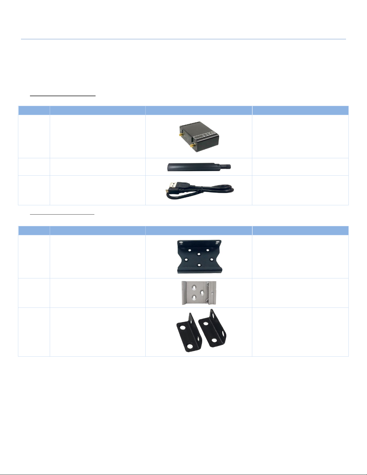
1.2.1 Package Contents................................................................................................................... 5
1.3 Hardware Configuration .................................................................................................................. 5
1.4 LED Indication................................................................................................................................ 6
1.5 Installation & Maintenance Notice ................................................................................................... 7
1.5.1 SYSTEM REQUIREMENTS................................................................................................ 7
1.5.2 WARNING ........................................................................................................................... 7
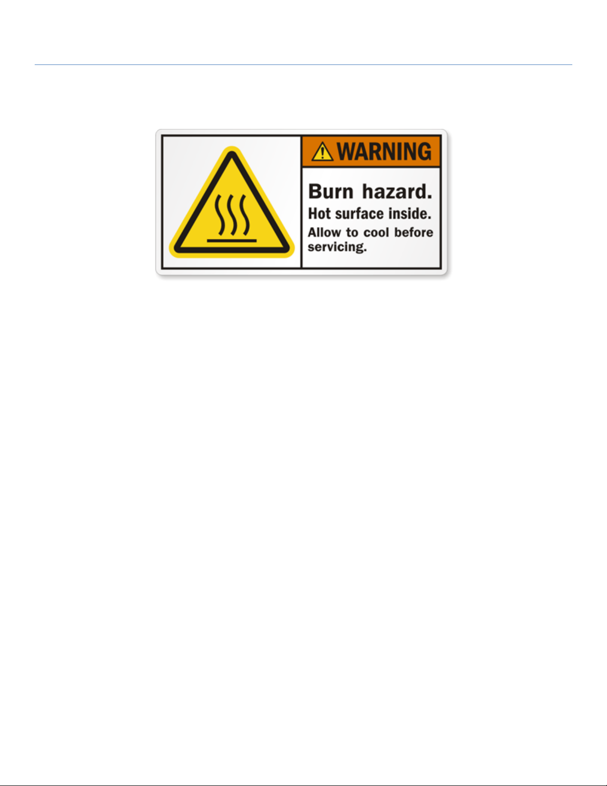
1.5.3 HOT SURFACE CAUTION.................................................................................................. 9
1.5.4 Product Information for CE RED Requirements ................................................................... 10
1.6 Hardware Installation..................................................................................................................... 12
1.6.1 Mount the Unit.................................................................................................................... 12
1.6.2 Insert the SIM Card............................................................................................................. 12
1.6.3 Connecting to USB Host...................................................................................................... 13
1.6.4 Setup by Configuring WEB UI ........................................................................................... 13
Chapter 2 Setup............................................................................................................................................14
2.1 Network........................................................................................................................................ 14
2.1.1 Device Mode....................................................................................................................... 14
2.1.2 Cellular............................................................................................................................... 15
2.1.3 Ethernet............................................................................................................................... 17
2.1.4 Port Forwarding .................................................................................................................. 18
2.1.5 DDNS................................................................................................................................. 20
2.1.6 USB Mode.......................................................................................................................... 21
2.2 System ........................................................................................................................................... 21
2.2.1 System Time ........................................................................................................................ 21
2.2.2 Language ............................................................................................................................. 22
2.2.3 System Information.............................................................................................................. 22
2.2.4 Scheduling........................................................................................................................... 23
Chapter 3 Administrator................................................................................................................................24
3.1 Manager........................................................................................................................................ 24
3.1.1 FW Upgrade........................................................................................................................ 24
3.1.2 Password & MMI................................................................................................................ 25

4G USB Modem
3
3.1.3 Reboot & Reset................................................................................................................... 26
3.1.4 Telnet & SSH...................................................................................................................... 26
3.1.5 Remote Administrator .......................................................................................................... 27
3.2 Utility ........................................................................................................................................... 28
3.2.1 SMS ................................................................................................................................... 28

4G USB Modem
4
Chapter 1 Introduction
1.1 Introduction
Congratulations on your purchase of AMIT’s IDG400 M2M Cellular Modem. With this AMIT cellular modem
you have made a great first step in the world of connected Internet of things (IOT) by simply inserting a SIM
card from the local mobile carrier into this device to get things connected. This section gives you all the
information you need to set up your device.
Main Features:
Provide 3G/4G WAN connection.
Provide one USB 2.0 port for comprehensive connection.
Simple Web GUI is used for basic setting and check the 3G/4G status.
Designed easy-to-mount metal body for business and M2M environment to work with a variety M2M
(Machine-to-Machine) applications..
Before you install and use this product, please read this manual in detail for fully exploiting the functions of
this product.

4G USB Modem
5
1.2 Contents List
1.2.1 Package Contents
#Standard Package
Items
Description
Contents
Quantity
1
IDG400-0TU02
4G USB Modem
1pcs
2
Cellular Antenna
2pcs
MicroUSB Cable
1pcs
#Optional Package
Items
Description
Contents
Quantity
1
Extender
1pcs or 2 pcs
(1 pcs needed for din-rail and 2 pcs
needed for wall-mount)
2
DIN-Rail Bracket
1pcs
3
Wall-Mount
2pcs/set
1.3 Hardware Configuration
Left View

4G USB Modem
6
Right View
※Reset Button
RESET button provides user a quick and easy way to resort the default setting. Press the RESET button
continuously for 6 seconds, and then release it. The device will restore to factory default settings.
1.4 LED Indication
Indication
LED Color
Description
Power
Blue
Steady On: Device power is on
Off: Device power is off
Status
Blue
Red
Red Steady on: Cellular is not ready or no cellular signal.
Red Flash: Cellular is ready but regiister status is not ready.
Blue Steady On: The signal is ready and regists to operator.
Blue Fast Flash: State on LTE.
3G/4G
Antenna
USB & Power
SIM
Slot
3G/4G
Antenna
Reset
Button

4G USB Modem
7
Blue Slow Flash: State on 3G.
1.5 Installation & Maintenance Notice
1.5.1 SYSTEM REQUIREMENTS
Network Requirements
USB 2.0 Host Port
3G/4G cellular service subscription
Web-based Configuration Utility
Requirements
Computer with the following:
Windows®, Macintosh, or Linux-based operating
system
An USB Host Portr
Browser Requirements:
Internet Explorer 10.0 or higher
Chrome 73 or higher
Firefox 60.0 or higher
1.5.2 WARNING
Only use the data cable that comes with the
package.
Over voltage rating is dangerous and may damage
the product.
Do not open or repair the case yourself. If the
product is too hot, turn off the power immediately
and have it repaired at a qualified service center.
Place the product on a stable surface and avoid
using this product and accessories outdoors.
Attention

4G USB Modem
8
Federal Communication Commission Interference Statement
This device complies with Part 15 of the FCC Rules. Operation is subject to the following two conditions: (1) This device may
not cause harmful interference, and (2) this device must accept any interference received, including interference that may
cause undesired operation.
This equipment has been tested and found to comply with the limits for a Class B digital device, pursuant to Part 15 of the
FCC Rules. These limits are designed to provide reasonable protection against harmful interference in a residential
installation. This equipment generates uses and can radiate radio frequency energy and, if not installed and used in
accordance with the instructions, may cause harmful interference to radio communications. However, there is no guarantee
that interference will not occur in a particular installation. If this equipment does cause harmful interference to radio or
television reception, which can be determined by turning the equipment off and on, the user is encouraged to try to correct
the interference by one of the following measures:
- Reorient or relocate the receiving antenna.
- Increase the separation between the equipment and receiver.
- Connect the equipment into an outlet on a circuit different from that to which the receiver is connected.
- Consult the dealer or an experienced radio/TV technician for help.
FCC Caution: Any changes or modifications not expressly approved by the party responsible for compliance could void the
user's authority to operate this equipment.
This transmitter must not be co-located or operating in conjunction with any other antenna or transmitter.
FOR PORTABLE DEVICE USAGE (<20m from body/SAR needed)
Radiation Exposure Statement:
The product comply with the FCC portable RF exposure limit set forth for an uncontrolled environment and are safe for
intended operation as described in this manual. The further RF exposure reduction can be achieved if the product can be
kept as far as possible from the user body or set the device to lower output power if such function is available.
FOR MOBILE DEVICE USAGE (>20cm/low power)
Radiation Exposure Statement:
This equipment complies with FCC radiation exposure limits set forth for an uncontrolled environment. This
equipment should be installed and operated with minimum distance 20cm between the radiator & your body.
FOR COUNTRY CODE SELECTION USAGE (WLAN DEVICES)
Note: The country code selection is for non-US model only and is not available to all US model. Per FCC regulation, all
WiFi product marketed in US must fixed to US operation channels only.

4G USB Modem
9
1.5.3 HOT SURFACE CAUTION
CAUTION: The surface temperature for the metallic enclosure can be very high!
Especially after operating for a long time, installed at a closed cabinet
without air conditioning support, or in a high ambient temperature
space.
DO NOT touch the hot surface while servicing!!

4G USB Modem
10
1.5.4 Product Information for CE RED Requirements
The following product information is required to be presented in product User Manual for latest CE RED
requirements.
1
(1) Frequency Band & Maximum Power
1.a Frequency Band for Cellular Connection (for EC25-EU version)
Band number
Operating Frequency
Max output power
LTE FDD BAND 1
Uplink: 1920-1980 MHz
Downlink: 2110-2170 MHz
23.1 dBm
LTE FDD BAND 3
Uplink: 1710-1785 MHz
Downlink: 1805-1880 MHz
23.0 dBm
LTE FDD BAND 7
Uplink: 2500-2570 MHz
Downlink: 2620-2690 MHz
22.8 dBm
LTE FDD BAND 8
Uplink: 880-915 MHz
Downlink: 925-960 MHz
23.2 dBm
LTE FDD BAND 20
Uplink: 832-862 MHz
Downlink: 791-821 MHz
23.5 dBm
LTE FDD BAND 28A
Uplink: 704 -723 MHz
Downlink: 759 - 778MHz
23 dBm
LTE FDD BAND 38
Uplink: 2570-2620 MHz
Downlink: 2570-2620 MHz
21.7 dBm
LTE FDD BAND 40
Uplink: 2300-2400 MHz
Downlink: 2300-2400 MHz
21.5 dBm
WCDMA BAND 1
Uplink: 1920-1980 MHz
Downlink: 2110-2170 MHz
23.3 dBm
WCDMA BAND 8
Uplink: 880-915 MHz
Downlink: 925-960 MHz
E-GSM
Uplink: 880-915 MHz
Downlink: 925-960 MHz
32.9 dBm
DCS
Uplink: 1710-1785 MHz
Downlink: 1805-1880 MHz
29.9 dBm
1.b Frequency Band for Cellular Connection (for Quectel EC25-AF version)
Band number
Operating Frequency
Max output power
LTE FDD BAND 2
Uplink: 1850-1910 MHz
Downlink: 1930-1990 MHz
23.86 dBm
LTE FDD BAND 4
Uplink: 1710-1755 MHz
Downlink: 2110-2155 MHz
23.82 dBm
LTE FDD BAND 5
Uplink: 824-849 MHz
23.46 dBm
1
The information presented in this section is ONLY valid for the EU/EFTA regional version. For those non-
CE/EFTA versions, please refer to the corresponding product specification.

4G USB Modem
11
Downlink: 869-894 MHz
LTE FDD BAND 12
Uplink: 699-716 MHz
Downlink: 729-746 MHz
23.75 dBm
LTE FDD BAND 13
Uplink: 777-787 MHz
Downlink: 746-756 MHz
23.86 dBm
LTE FDD BAND 14
Uplink: 788-798 MHz
Downlink: 758-768 MHz
23.86 dBm
LTE FDD BAND 66
Uplink: 1710-1780 MHz
Downlink: 2100-2200 MHz
23.34 dBm
LTE FDD BAND 71
Uplink: 663-698 MHz
Downlink: 617-652 MHz
23.46 dBm
WCDMA BAND 2
Uplink: 1850-1910 MHz
Downlink: 1930-1990 MHz
23.3 dBm
WCDMA BAND 4
Uplink: 1710-1755 MHz
Downlink: 2110-2155 MHz
WCDMA BAND 5
Uplink: 824-849 MHz
Downlink: 869-894 MHz
(2) DoC Information
You can get the DoC information of this product from the following URL:
http://www.amitwireless.com/products-doc/
(3) RF Exposure Statements
To comply with RF exposure limits established in FCC, the distance between the antenna or antennas and
the user should not be less than 20 cm (7.87”).
(4) Unit Mounting Notice
The product is suitable for mounting at heights <= 2m (approx. 6 ft), or in a cabinet.
Ensure the unit is fixed tightly to reduce the likelihood of injury due to exposure to mechanical hazards if
dropped.
(5) Manufacture Information
Manufacture Name: AMIT Wireless Inc.
Manufacture Address: No. 28, Lane 31, Sec. 1, Huandong Rd., Sinshih Dist., Tainan 74146, Taiwan

4G USB Modem
12
1.6 Hardware Installation
This chapter describes how to install and configure the hardware
1.6.1 Mount the Unit
The IDG400 series can be placed on a desktop, or use extender to place on DIN-Rail bracket or mount on the
wall.
1.6.2 Insert the SIM Card
WARNING: BEFORE INSERTING OR CHANGING THE SIM CARD, PLEASE MAKE SURE
THAT POWER OF THE DEVICE IS SWITCHED OFF.
SIM card slot is located in the middle area of IDG400 series. You need to remove the outer SIM card
cover before installing or removing an inserted SIM card. Please follow below instructions to install or remove
a SIM card. After SIM card is well installed or removed, put back the outer SIM card cover.
Step 1: Remove SIM cover
Remove the SIM cover from
left side.
Step 3: Insert a SIM
Push the SIM card into the
SIM slot.
Step 2: Remove SIM
Push the inserted SIM card
to eject the SIM card.
Step 4: Put Back SIM cover
Put back the SIM cover

4G USB Modem
13
1.6.3 Connecting to USB Host
This product provides one Micro-USB port to be data interface and power path. When the device is
connected to USB host port, it will be identified a RNDIS interface as a network adapter. RNDIS class is driver-
ready in Linux, FreeBSD and Windows. User can have internet and an easy Web-GUI to config the product via
this network interface.
1.6.4 Setup by Configuring WEB UI
User can browse web UI to configure the device.
Type in the IP Address (http://192.168.123.254)
2
When you see the login page, enter the user name and password and then click ‘Login’ button.
The default setting for both username and password is ‘admin’
3
.
2
The default LAN IP address of this gateway is 192.168.123.254. If you change it, you need to login by using
the new IP address.
3
For security concern, the login process will force user to change default password at the first time.

4G USB Modem
14
Chapter 2 Setup
The product connects to a machine viaUSB port for 3G/4G network connection. This device provides
alternative functions between NAT router and Modem mode. It can help the network application more flexible.
2.1 Network
Network Page
Item
Description
Device Mode
Set the unit operating mode
Cellular
Set the parameter for cellular network.
Ethernet
Set the IP of Ethernet and DHCP service
Port Forwarding
Enable specified port or protocol for service on connected device.
DDNS
Register a dynamic host name for the unit.
USB Mode
Select defult USB device mode between RNDIS and QMI.
2.1.1 Device Mode
Device Mode
Item
Value setting
Description
Device Mode
1. A Must filled setting
2. By default NAT is
selected
NAT
The unit will provide a NAT service and provide a simple firewall for the
connected device.
Modem
The unit will pass the cellular IP to connected device via ethernnet

4G USB Modem
15
2.1.2 Cellular
Device Mode
Item
Value setting
Description
APN
1. A Must filled setting
2. By default Auto is
selected
Auto
The unit will detect the SIM and set an APN from internal database.
Manual
User must set APN manually.
Manual APN
1. A Must filled setting
2. String format : any
text
Enter the APN you want to use to establish the connection.
This is a must-filled setting if you selected Manual APN as APN scheme.
Username
1. An Optional setting
2. String format : any
text
Enter the optional username settings if your ISP provided such settings to
you.
Password
1. An Optional setting
2. String format : any
text
Enter the optional Password settings if your ISP provided such settings to
you.
Authentication
1. A Must filled setting
2. By default Auto is
selected
Select PAP (Password Authentication Protocol) and use such protocol to be
authenticated with the carrier’s server.
Select CHAP (Challenge Handshake Authentication Protocol) and use such
protocol to be authenticated with the carrier’s server.
When Auto is selected, it means it will authenticate with the server either
PAP or CHAP.
IP Type
1. A Must filled setting
2. By default IPv4 is
selected
Specify the IP type of the network service provided by your 3G/4G network.
It can be IPv4, IPv6, or IPv4v6.

4G USB Modem
16
IP Mode
1. A Must filled setting
2. By default Dynamic IP
is selected
Dynamic IP
The unit will get IP from cellular service..
Static IP
The unit will set IP according Static IP Config.
PIN Code
1. An Optional setting
2. String format :
interger
Enter the PIN (Personal Identification Number) code if it needs to unlock your
SIM card.
MTU Setup
1. An Optional setting
2. Uncheck by default
Check the Enable box to enable the MTU (Maximum Transmission Unit) limit,
and specify the MTU for the 3G/4G connection.
MTU refers to Maximum Transmission Unit. It specifies the largest packet size
permitted for Internet transmission.
Value Range: 68 ~ 1500.
Keep Alive
1. An optional setting
2. Box is unchecked by
default
Check the Enable box to activate the keep alive function.
Input IP Address and interval to send an ICMP packet to check the network
status.
Static IP Configuration
Item
Value setting
Description
IP
1. IPv4 format.
2. A Must filled setting
The Static IP Address setting of this unit.
Subnet Mask
255.255.255.0 (/24) is
set by default
The Subnet Mask of this configed static IP.
Default Gateway
1. IPv4 format.
2. An Optional setting
The gateway setting of this configed static IP.
Primary DNS
1. IPv4 format.
2. An Optional setting
Assigned DNS server of this configed static IP.
Secondary DNS
1. IPv4 format.
2. An Optional setting
Assigned DNS server of this configed static IP.

4G USB Modem
17
2.1.3 Ethernet
Ethernet IP
Item
Value setting
Description
IP
1. IPv4 format.
2. A Must filled setting
The LAN IP Address of this unit.
Netmask
255.255.255.0 (/24) is
set by default
The Subnet Mask of this unit.
DHCP Server
The box is unchecked by
default.
Click Enable box to activate DHCP Server.
DHCP Setting
N/A
Click DHCP Config button to pop-up the DHCP Setting page.
DHCP Setting
Item
Value setting
Description
IP Pool Start
1. Numberic string
format.
2. A Must filled setting
The IP Pool of this DHCP Server. It is Starting Address entered in this field.
IP Pool End
1. Numberic string
The IP Pool of this DHCP Server. It is Ending Address entered in this field.

4G USB Modem
18
format.
2. A Must filled setting
Lease Time
1. Numberic string
format.
2. A Must filled setting
The Lease Time of this DHCP Server.
Value Range:300 ~ 604800 seconds.
2.1.4 Port Forwarding
Virtual Server
Item
Value setting
Description
Virtual Server
The box is unchecked by
default
Check the Enable box to activate this port forwarding function
Click Add will pop-up Virtual Server Rule Configuration page.

4G USB Modem
19
Virtual Server Rule Configuration
Item
Value setting
Description
Name
1. String format can be
any text
2. A Must filled setting
The name of current rule
Server IP
A Must filled setting
This field is to specify the IP address of the interface selected in the WAN
Interface setting above.
Source IP
1. A Must filled setting
2. By default Any is
selected
This field is to specify the Source IP address.
Select Any to allow the access coming from any IP addresses.
Select Specific IP Address to allow the access coming from an IP address.
Select IP Range to allow the access coming from a specified range of IP
address.
Protocol
A Must filled settin
When “TCP(6)”is selected
It means the option “Protocol” of packet filter rule is TCP.
Public Port selected a predefined port from Well-known Service, and Private
Port is the same with Public Port number.
Public Port is selected Single Port and specify a port number, and Private
Port can be set a Single Port number.
Public Port is selected Port Range and specify a port range, and Private Port
can be selected Single Port or Port Range.
Value Range: 1 ~ 65535 for Public Port, Private Port.
When “UDP(17)”is selected
It means the option “Protocol” of packet filter rule is UDP.
Public Port selected a predefined port from Well-known Service, and Private
Port is the same with Public Port number.
Public Port is selected Single Port and specify a port number, and Private
Port can be set a Single Port number.
Public Port is selected Port Range and specify a port range, and Private Port
can be selected Single Port or Port Range.
Value Range: 1 ~ 65535 for Public Port, Private Port.
When “TCP(6) & UDP(17)”is selected
It means the option “Protocol” of packet filter rule is TCP and UDP.
Public Port selected a predefined port from Well-known Service, and Private
Port is the same with Public Port number.
Public Port is selected Single Port and specify a port number, and Private
Port can be set a Single Port number.
Public Port is selected Port Range and specify a port range, and Private Port
can be selected Single Port or Port Range.
Value Range: 1 ~ 65535 for Public Port, Private Port.
When “User-defined” is selected
It means the option “Protocol” of packet filter rule is User-defined.
For Protocol Number, enter a port number.
Rule
1. An optional filled
setting
Check the Enable box to activate the rule.

4G USB Modem
20
2.The box is unchecked
by default.
Virtual Server –Rule Name
Item
Value setting
Description
Rule name
N/A
Clicl “Edit”button to pop-up Virtual Server Rule Configuration page to edit
the rule.
Click “Delete”button to delete this rule
2.1.5 DDNS
DDNS
Item
Value setting
Description
DDNS
The box is unchecked by
default
Check the Enable box to activate this function.
Provider
DynDNS.org is set by
default
Select your DDNS provider of Dynamic DNS. It can be DynDNS.org, NO-
IP.com, TZO.com etc...
Host Name
1. String format can be
any text
2. A Must filled setting
Your registered host name of DDNS Service.
Value Range:0 ~ 63 characters.
User Name / E-Mail
1. String format can be
any text
2. A Must filled setting
Enter your User name or E-mail addresss of DDNS Service.
Password / Key
1. String format can be
any text
2. A Must filled setting
Enter your Password or Key of DDNS Service.
Table of contents
Other Amit Modem manuals

Amit
Amit IDG450-WG001 User manual

Amit
Amit MDG230-0G001 User manual

Amit
Amit MDG100-0TM01 User manual

Amit
Amit IDG450-0GD0C User manual

Amit
Amit IDG400-0TE0C User manual

Amit
Amit BMG500AM-0T1 User manual

Amit
Amit IDG470-WG001 User manual

Amit
Amit IDG400-0TE01 User manual

Amit
Amit IDG450-0GE01 User manual

Amit
Amit IDG450-0GT0C User manual