AML Oceanographic AML-1 RT User manual

AML-1 RT: User Manual
Multiparameter Real Time Instrument
For more information visit AMLoceanographic.com or call +1 250-656-0771

Revision History
Revision
Date
Description
1.1
29 Sept 2020
Document Created
1.2
27 April 2021
RS-485 Details Added
AML Oceanographic Ltd. 2/18

1 Introduction 4
1.1 Instrument Overview 4
1.2 Connectors and Cables 5
2 Getting Started 6
2.1 Interacting with the instrument 6
2.1.1 Typical Startup Sequence 6
2.1.2 Sensor Bootup 7
2.1.3 Streaming Data 7
2.1.4 Monitoring (Streaming) Data 8
2.1.5 Applications of Automonitor 8
2.1.6 Baud Rates 9
2.2 Common Settings and Configurations 9
2.2.1 Commands for Sound Velocity Sensors (SV and SVT•Xchange) 9
2.2.2 Commands for Pressure Sensors (P•Xchange) 11
3 Instrument Maintenance 12
4 Appendix A - Equipping an Instrument 13
4.1 Installing sensors 13
5 Appendix B - Contact AML 14
5.1 Service 14
5.2 Sales 14
6 Appendix C - Regulatory and Warranty Statements 15
AML Warranty Policy: New Product (Instrumentation) 15
7 Technical Overview 16
AML Oceanographic Ltd. 3/18

1 Introduction
The AML-1 RT is an ultra-compact externally powered single port instrument that provides real
time (streaming) serial data from any AML X2changeTM sensor. Compatible sensors are
identified by their distinct orange collars.
There are a number of common applications for these devices, including:
● Pairing an AML-1 RT instrument with a Sound Velocity sensor to provide real time sound
speed measurements for MBES applications
● Mounting a pressure sensor-equipped AML-1 RT on an underwater vehicle to stream
depth information
● Installing an AML-1 with a combined conductivity and temperature sensor to calculate
salinity data on a moored platform in real time.
The instrument relies on external power for operation and comes equipped with a single
wet-mateable connector to facilitate power and data transmission.
The instrument itself has no configuration, but instead provides access to the command prompt
of the installed sensor. Configured behaviour such as baud rate, measurement frequency,
formatting, etc, is programmed and persistent within the installed sensor, not the
AML1-RT instrument. For this reason, behaviour of the instrument may change with the
installation of a new sensor, even if the parameter is identical to one previously installed.
1.1 Instrument Overview
Specifications
The following table describes specifications of the instrument only, unless noted otherwise.
Table 1: AML-1 RT specifications
Depth rating
6000 meters / 19,685 feet
Material
Titanium
Communication
(RS-232)
Wet-Mate MCBH-6 Female, RS-232 Serial Communication
(Bi-Directional Communication)
Communication
(RS-485)
Wet-Mate MCBH-6 Female, RS-485 Half Duplex Serial
Communication (One-way communication from instrument to
host)
Power
Input voltage of 8-30V
AML Oceanographic Ltd. 4/18

70mA at 8V, 20mA at 30V 1
Temperature
Operation
Storage
-20 to +45°C
-20 to +60°C
Dimensions
Diameter
Length
Weight
Weight in water
3.3 cm / 1.3 in
10.74 cm / 4.23 in (no sensor installed),
20.01cm / 7.88 in (SV•X2changeTM sensor installed)
0.2 kg / 0.4 lb (no sensor installed)
0.11 kg / 0.25 lb (no sensor installed)
1 - Typical power draw when an SV sensor is installed. Other sensors may draw a different power.
1.2 Connectors and Cables
The AML-1 RT has only one connector, a 6-pin female (MCBH6F), located on the face opposite
the sensor port. This connector is used to provide external power and serial communication
during deployment. The instrument is factory set to either RS-232 or RS-485. The pin diagram
for the connector is shown in Figure 1 below. Accompanying cables of various lengths are
available with the AML-1 RT. Contact AML for details.
Pin
RS-232
RS-485
1
Rx - Signal
Tx - Signal B
2
Ground
Ground
3
Power (8-30 V)
Power (8-30 V)
4
Tx – Signal
Tx - Signal A
5
N/C
N/C
6
N/C
N/C
Figure 1: Left: Table of pin numbers and purposes. Right: Drawing of 6-pin female connector
AML Oceanographic Ltd. 5/18

2 Getting Started
This section provides an overview of basic instrument operation and functionality under a
factory-default setup for most sensors. Specifically, this section describes how to connect to the
instrument, change settings via terminal emulator, and stream sensor measurements.
Note that configuration is controlled within an installed sensor (not the AML-1 RT instrument), so
some commands, features, and settings are sensor-specific.
Details describing how to change configuration and behaviour are described in Section 2.2.
2.1 Interacting with the instrument
Interaction with the AML-1 RT is facilitated by means of a terminal emulation program such as
HyperTerminal, RealTerm, or Tera Term. Communication with the instrument must be
established using the correct communications port and settings, described below:
● 8 bits
● 1 stop bit
● No parity
● No hardware handshaking
● Baud rate of 600, 1200, 2400, 4800, 9600, 19,200 or 38,400 baud
○ 9600 is the default baud rate.
The default baud rate for most installed sensors is 9600. Note that this is not guaranteed
however, as some sensors may be factory-configured to an alternative baud rate depending on
application or request.
2.1.1 Typical Startup Sequence
To get an AML-1 RT device up and running, follow the procedure described below:
1. Ensure a sensor is fully installed on the port of the AML-1 RT instrument. The orange
sensor collar should be hand-tight. Do not use tools to tighten the collar. Refer to
Appendix A - Equipping an instrument for further details on installing a sensor.
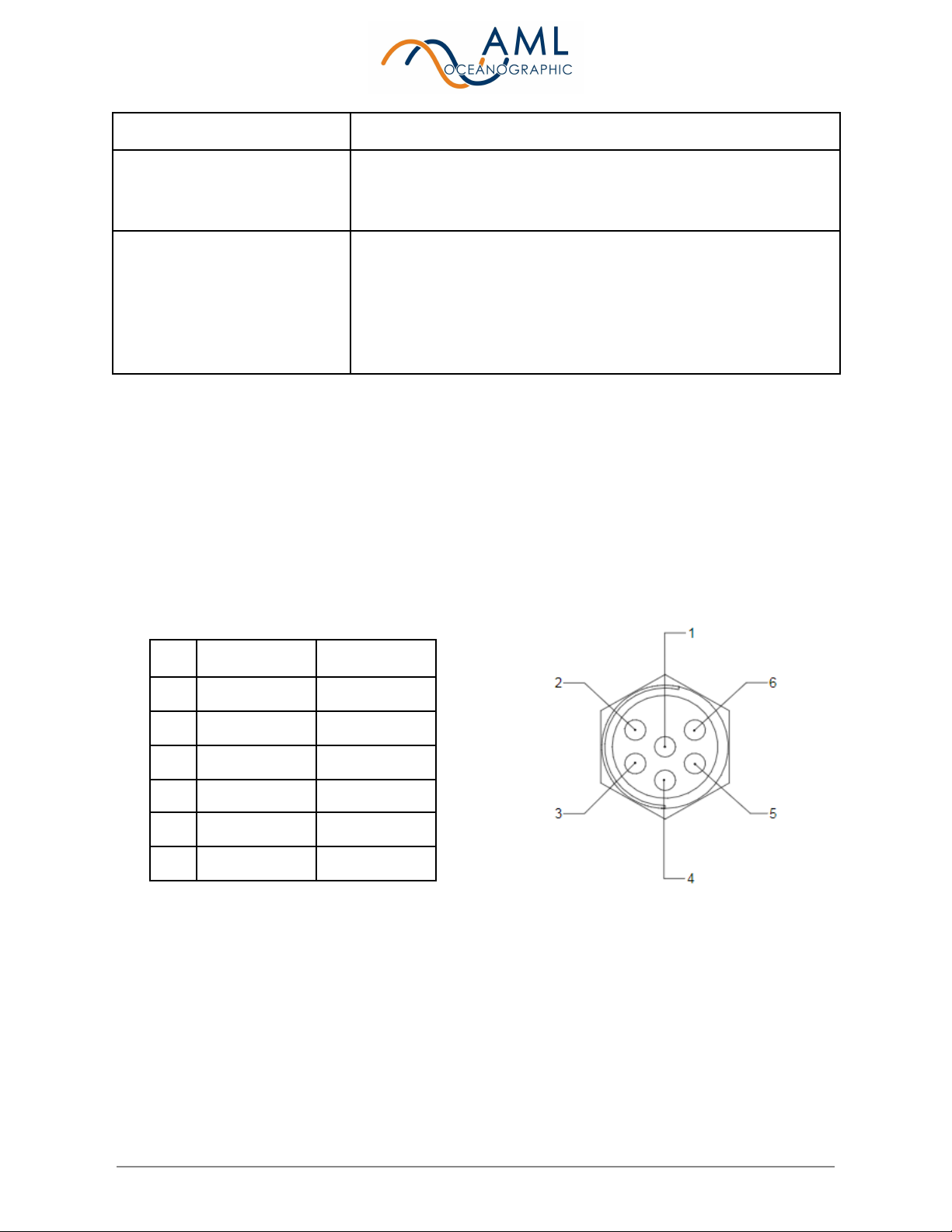
2. Connect the provided underwater cable to the wet-mate connector on the end of the
instrument. The opposing end of the cable will likely have a DB9 serial connector and
flying power leads. Connect the serial cable to the PC via a serial port or USB-serial
adapter.
3. Using a terminal emulator, configure the serial port as described in the previous section
(Section 1.2) and open the serial port.
AML Oceanographic Ltd. 6/18

4. Connect the flying leads to a power source (8-30V) and apply power. This will
immediately cause the instrument and sensor to boot.
2.1.2 Sensor Bootup
The basic startup sequence for all X2change sensors is identical. Default operation is for output
to commence with a continuously transmitted identifying header sentence. This sentence is
repeated at a rate of 20 Hz for approximately 2 seconds, after which the device automatically
switches to streaming measurement data at a rate of 25 Hz.
An example bootup sequence is shown to the
right. Upon the application of power, the
X2Change sensor streams an identification
header for 2 seconds, then switches to
monitor mode where it will continuously
stream data at a rate of 25 Hz.
In this example, the Sound Velocity sensor is
in air so it is measuring 0000.000 m/s.
It is possible to interrupt the identifying header
by sending a carriage return. The device will
then switch to streaming measurements.
@S 209922 01/01/2000 0.021 SV.X 2d
0000.000
0000.000
0000.000
0000.000
...
2.1.3 Streaming Data
After bootup, data streaming will continue indefinitely until interrupted by a power cycle or by
sending any ASCII character. When halted, the AML-1 RT will land at a command prompt, as
shown below:
0000.000
0000.000
0000.000
0000.000
0000.000
0000.000
>
AML Oceanographic Ltd. 7/18

It is possible to configure the automatic behavior of a sensor after it’s identification strain
transmission. For example, a sensor may be configured to land at prompt and await further
commands, or alternatively may be configured to immediately stream data (the default behavior
described here). For sound velocity sensors (SV and SVT•Xchange), relevant commands are
listed in Section 2.2 - Common Settings and Configuration.
2.1.4 Monitoring (Streaming) Data
To commence streaming data, send the monitor command:
>monitor
0000.000
0000.000
0000.000
0000.000
0000.000
0000.000
0000.000
0000.000
…
The instrument will stream measurements indefinitely until halted.
2.1.5 Applications of Automonitor
In some applications it is undesirable to have streaming data interrupted by receipt of any ASCII
character. For example, noise on a communication line may be inadvertently interpreted as a
character, halting sensor operation. In these cases, best practice is to configure the sensor to
automatically recommence data streaming after a period of inactivity when at prompt. This is
achieved using the command set automon x, where ‘x’ is the elapsed time of inactivity in
milliseconds. For example, to configure a sensor to re-commence data streaming after 2
seconds of inactivity (when at prompt), send the following command:
>set automon 2000
>
0000.000
0000.000
0000.000
0000.000
...
In this configuration, if the instrument’s streaming data is halted (either deliberately or
inadvertently) then it will land at prompt, wait two seconds, then re-commence streaming. It is
recommended that this configuration be used for MBES applications.
Automonitor may be turned off by setting the period of inactivity to ‘0’: set automon 0.
AML Oceanographic Ltd. 8/18

2.1.6 Baud Rates
It is possible to alter the baud rate of the device. This is achieved by using the command set
outbaud x, where ‘x’ refers to the desired baud rate. For example, to switch to a baud rate of
19200, send the following:
>set outbaud 19200
Switching to 19200 baud now. Please adjust terminal baud rate
÷
Note that the baud rate adjustment occurs immediately, without the requirement for a power
cycle.
This command is persistent. Output data will be transmitted at this baud rate until it is changed
again via command.
Baud rate adjustment applies to all instrument interaction after the startup identifying header is
complete, but it does not adjust the baud rate at which the identification head string is
communicated. The startup header will always remain at 9600 baud unless adjusted by the
factory. For example, if the device is configured to use 19200 baud using set outbound 19200,
then after a power cycle the device will transmit its header information at 9600 baud for 2
seconds, then immediately switch to 19200 baud for the remainder of its operation.
Baud rate settings (like all settings) are sensor-specific, so if a non-default baud rate is used in
an application, sensors substituted in will require similar setup.
2.2 Common Settings and Configurations
It is common for an AML-1 RT to be paired with either an AML SV•X2changeTM (sound velocity
sensor) or SVT•X2changeTM (combined temperature and sound velocity sensor). Most
commands are common to both sensors, with the exception of some commands that adjust
temperature measurement functionality particular to the SVT sensor.
Most MBES stipulate a particular data format for compatibility and users should check with the
manufacturer for detailed requirements. It is possible to configure an SV or SVT-equipped
AML-1 RT to be compatible with the majority of MBES systems.
2.2.1 Commands for Sound Velocity Sensors (SV and
SVT•Xchange)
When paired with an SV or SVT sensor, the device will stream sound velocity measurements in
units of m/s, and temperature measurements (in the case of SVT) in units of oC.
AML Oceanographic Ltd. 9/18

The table below provides a summary of typical commands which are common to both SV and
SVT•Xchange sensors.
Table 2: Common Settings for both SV and SVT•X2changeTM sensors
Setting
Applicable Command
Description
Default
Alternate
Options
Identify
firmware
version
DISPLAY VERSION
Will provide sensor name and
installed firmware version
-
-
Monitor on
Startup
SET STARTUPMONITOR YES/NO
If YES, the instrument will start
streaming data when power is
applied. If NO, device will await a
command after header information.
Yes
No
Output Rate
SET OUTPUTRATE xxx
Time between provided
measurements in ms
(1/output frequency)
40ms
(25 Hz)
40ms-1000ms
Automonitor
SET AUTOMONITOR xxx
Instrument will start to stream data
after user interrupt, time specified in
milliseconds of inactivity
0s, will
not start
streaming
User
configurable up
to 100s
Leadingspace
SET LEADINGSPACE YES/NO
Adds a leading space to the output
stream. Used to emulate output
from legacy Micro•X instruments.
no
yes
Format of SV
output
SET SVFORMAT XY
X is number of digits before
decimal. Y is number of digits after
decimal.
43
(xxxx.yyy)
User
configurable
Baud rate
SET BAUD x
X is desired baud rate. Effective
immediately (without power cycle).
Does not alter ident. header baud
rate.
9600
9600, 19200,
38400, 57600
115200
SV sample
averaging
SET SVAVG x
Rolling ‘boxcar’ average.
Continuously averages last ‘x’
samples. Note: increasing averages
will smooth output data but reduce
response time.
8
1-100
SVT•Xchange sensors have some additional functionality pertaining to temperature
measurements. These commands are summarized below.
Table 3: Common Settings for SVT•X2changeTM sensors
Setting
Applicable Command
Description
Default
Alternate
Options
Temperature
format
SET TEMPFORMAT xy
X is number of digits before
decimal. Y is number of digits after
decimal.
‘23’
(‘XY’ =
xx.yyy)
User
configurable
Temperature
output on/off
SEC 652
TEMPDISPLAY YES/NO
Controls whether or not a second
column is streamed displaying
yes
no
AML Oceanographic Ltd. 10/18

temperature.
This is a secure command, and
must be preceded with ‘SEC 652’.
Temperature
averaging
SET TEMPAVG x
Rolling ‘boxcar’ average.
Continuously averages last ‘x’
samples. Note: increasing averages
will smooth output data but reduce
response time.
4
1-100
2.2.2 Commands for Pressure Sensors (P•Xchange)
When paired with a pressure sensor, the device will stream measurements in units of dBar.
The table below summarizes typically used commands for P•X2change sensors.
Table 3: Common Settings for P•X2changeTM sensors
Setting
Applicable Command
Description
Default
Alternate
Options
Identify
firmware
version
DISPLAY VERSION
Will provide sensor name and
installed firmware version
-
-
Baud rate
SEC 652
SET BAUD x
X is desired baud rate. Effective
immediately (without power cycle).
Does not alter ident. header baud
rate.
9600
9600, 19200,
38400, 57600
115200
Automonitor
SET AUTOMONITOR xxx
Instrument will start to stream data
after user interrupt, time specified
in milliseconds of inactivity
0s, will
not start
streaming
User
configurable up
to 100s
Taring the
sensor
ZERO
Will automatically tare the sensor
by applying current readings as an
offset. This command should be
applied while the sensor is in air.
-
-
Data format
SET DATAFORMAT xy
X is number of digits before
decimal. Y is number of digits after
decimal.
2
4
Pressure
averaging
SET SAMPLESTOAVERAGE x
Rolling ‘boxcar’ average.
Continuously averages last ‘x’
samples. Note: increasing
averages will smooth output data
but reduce response time.
1
1-4096
AML Oceanographic Ltd. 11/18

3 Instrument Maintenance
Periodic preventative maintenance will prolong the life of the instrument. The following steps are
recommended:
● If the instrument is dirty or oily, allow it to soak in warm, soapy water before cleaning with
a rag or soft brush. When finished, rinse with fresh water to remove any residual soap or
dirt.
● Before each use:
○ Check for proper installation of the X2change™ sensor (Appendix B)
○ Check for nicks and cuts on the cable.
● After each use:
○ Clean and rinse the instrument using fresh water.
○ Dry the instrument completely, and store it in a cool, dry place.
● Monthly:
○ Apply a layer of Molykote 44 medium silicone grease to the female half of the
connection as shown and fully insert the plug. Wipe away any excess that
squeezes out. This will lubricate both male and female connectors.
● Yearly:
○ Send the instrument or X2changeTM sensors to a service centre for diagnostics
and re-calibration
AML Oceanographic Ltd. 12/18

4 Appendix A - Equipping an Instrument
AML-1 RT is part of AML’s X2change instrumentation ecosystem. Any sensor within this
ecosystem is compatible with any instrument. Sensors are identified by orange collars, and
instruments are identified by black decals on the instrument body and orange colouring within
the sensor ports. Only ‘orange’ sensors may be installed on ‘orange’ instruments. The previous
generation of blue-collar Xchange sensors are not compatible.
The process below describes the typical method for installing and removing sensors from an
instrument.
4.1 Installing sensors
1. Before installing X2Change™ sensors, ensure that the sensor port is clean and dry. Also
confirm that the port is ‘orange’ compatible by visually confirming the precedence of
orange coloring at the bottom of the port.
2. Check the X2Change™ sensor’s o-rings for cleanliness and replace if damaged. Apply
o-ring grease to the new o-ring before replacing it.
3. Align the sensor with the sensor port so that the key of the mating connector pins are
aligned. Key alignment is important - it can be difficult to insert a sensor if the clocking is
not correct.
4. Place the sensor into the port and press the sensor in to compress the o-rings. Confirm
correct alignment of the key by pressing the sensor body into the port and twisting the
sensor. It will be possible to feel the key engage.
5. Push the sensor until it drops down into the port enough to allow the orange locking
sleeve threads to engage the port threads.
6. Hand-tighten the orange locking sleeve until it stops. The bottom of the sleeve should be
within 1 mm of the instrument end cap. Note: the collar is NOT intended to sit flush on
the instrument endcap. Never use tools to tighten the locking collar.
AML Oceanographic Ltd. 13/18

5 Appendix B - Contact AML
5.1 Service
To request an RMA or technical support
Email: [email protected]
Phone: 1-250-656-0771
Phone: 1-800-663-8721 (NA)
http://www.AMLoceanographic.com
5.2 Sales
For all general sales inquiries
Email: [email protected]
Phone: 1-250-656-0771
Phone : 1-800-663-8721 (NA)
http://www.AMLoceanographic.com
AML Oceanographic Ltd. 14/18

6 Appendix C - Regulatory and Warranty
Statements
This product is compliant within the requirements of CE standards.
AML Warranty Policy: New Product (Instrumentation)
AML warrants the instrument and sensor for a period of TWO YEARS (24 months) from the date
of delivery. AML will repair or replace, at its option and at no charge, components which prove to
be defective. The warranty applies only to the original purchaser of the instruments and only to
instruments and sensors manufactured by AML Oceanographic. The warranty of third party
sensors will apply as per the specific vendor’s warranty policy. The warranty does not apply if
the instrument has been damaged, by accident or misuse, and is void if repairs or modifications
are made by other than authorized personnel.
This warranty is the only warranty for new products given by AML. No warranties implied by law,
including but not limited to the implied warranties of merchantability and fitness for a particular
purpose shall apply. In no event will AML be liable for any direct, indirect, consequential or
incidental damages resulting from any defects or failure of performance of any instrument
supplied by AML.
AML Oceanographic Ltd. 15/18

7 Technical Overview
AML Oceanographic Ltd. 16/18

AML Oceanographic Ltd. 17/18

AML Oceanographic Ltd. 18/18
Table of contents
Other AML Oceanographic Marine Equipment manuals

AML Oceanographic
AML Oceanographic AML-3 User manual

AML Oceanographic
AML Oceanographic MVP-X User manual

AML Oceanographic
AML Oceanographic Minos SVP User manual

AML Oceanographic
AML Oceanographic AML-3 LGR User manual

AML Oceanographic
AML Oceanographic AML-6 RT User manual

AML Oceanographic
AML Oceanographic RTS Series User manual

AML Oceanographic
AML Oceanographic Micro SVT User manual

AML Oceanographic
AML Oceanographic PDC-DCC-05 User manual

AML Oceanographic
AML Oceanographic MVP Manual

AML Oceanographic
AML Oceanographic MVP30 Manual