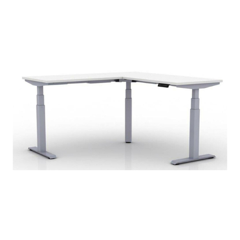
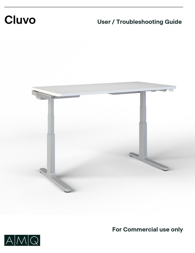
AMQ Cluvo User manual

Cluvo Assembly Guide
For Commercial use only

Contents
Safety Statement ............................................3-5
Hardware, Components & Optional Accessories ...................7
Preparing for Assembly .........................................8
9Stretcher Frame & Column Preassembly ..........................
10-11Adjusting the Stretcher Frame & Columnon Preassembly........
Attaching the Cantilevers .......................................12
13-16
Attaching Stretcher Frame ...................................
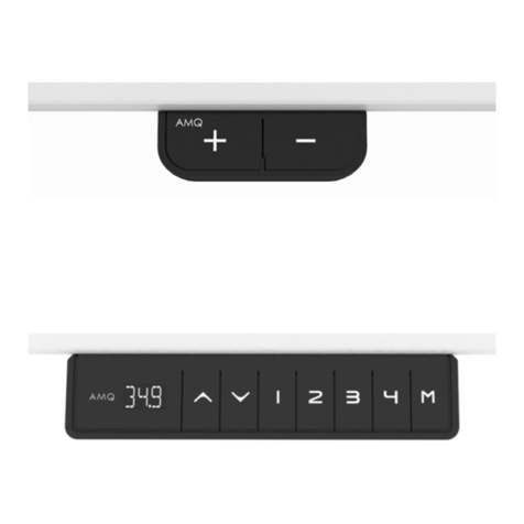
Attaching Standard Handset ....................................17
Attaching Deluxe Handset ......................................18
Feet Assembly ................................................19
Handle Cover Assembly ........................................20
Connecting Handset and Power ................................ 21
23-25
Attaching Cable Tray (Optional) .............................
26-27
Attaching ColumnSleeve (Optional) ..........................
Attaching Utility Hook .........................................22
28-29Replacing Glides with Castors (Optional) .....................
FCC Statement ................................................6
amqsolutions.comCluvo Assembly Guide | 2

Safety Statement
When using an electrical furnishing, basic precautions should always be followed,
including the following:
DANGER - To reduce the risk of electric shock: Always unplug this furnishing from the electrical
outlet before cleaning or servicing.
WARNING – To reduce the risk of burns, fire, electric shock or injury to persons:
1.
2.
3.
4.
5.
6.
7.
8.
9.
10.
11.
12.
13.
14.
The desk or table shall be positioned near power socket and the plug shall be easily accessible.
WARNING: Risk of Electric Shock – Connect this furnishing to a properly grounded
outlet only. See Grounding Instructions.
Cluvo height adjustable base model CLS2B and CLS3B doesn't include a worksurface.
WARNING
GROUNDED
OUTLET
GROUNDED
OUTLET BOX
GROUNDING PIN
Figure 1
Grounding methods
Products with Grounded Plugs
For products sold in North America and other 120V regions: the product
is for use on a nominal 120-V circuit.
These products use a grounded plug that look like the plug illustrated below.
Make sure that the product is connected to an outlet having the same
configuration as the plug.
No adapter should be used with this product.
•
•
•
•
The base is not complete until assembled with a worksurface.
Read instructions to determine the appropriate size, shape, and weight of the worksurface to be used.
The worksurface to be installed must have a flame spread< 200 and a smoke developed index < 450 when
evaluated by UL723 or ASTM E162.
This base is not designed to stand on its own. Failure to follow the installation procedures of attaching
stretcher frame, cantilever and column (components of the base) first onto the worksurface may result
in TIP OVER resulting in death or serious injury.
•
•
•
•
IMPORTANT SAFETY INSTRUCTIONS
READ ALL INSTRUCTIONS BEFORE USING THIS FURNISHING. READ AND SAVE INSTRUCTIONS AND
CONFIRM CRITICAL COMPONENTS ARE IN PLACE BEFORE USE. This furnishing is intended for
commercial use only.
PLEASE SAVE THESE INSTRUCTIONS IN AN OBVIOUS PLACE FOR THE END USER AFTER
ASSEMBLY.
Unplug from outlet before putting on or taking off parts.
DO NOT OPERATE THIS EQUIPMENT UNLESS PROPERLY TRAINED. Read this guide first.
Use this furnishing only for its intended use as described in these instructions. Do not use
attachments not recommended by the manufacturer.
DO NOT ALLOW USE BY CHILDREN or people unable to understand the risks and to safely adjust
the desk.
Never operate this furnishing if it has a damaged cord or plug, if it is not working properly, if it has
been dropped or damaged, or dropped into water. Return the furnishing to a service center for
examination and repair.
Keep the cord away from heated surfaces.
Remove and secure power cord when not in use to prevent children from operating the desk unsupervised.
Never drop or insert any object into any opening.
Do not use outdoors.
Do not operate where aerosol (spray) products are being used or where oxygen is being administered.
To disconnect, turn all controls to the off position, then remove plug from outlet.
Use only SJT, minimum 18/3 AWG, 105 degree C cord.
Maximum load 250 lbs including worksurface and accessories assembled onto worksurface for Cluvo 2
stage height adjustable desk and base.
Maximum load 300 lbs including worksurface and accessories assembled onto worksurface for Cluvo 3
stage height adjustable desk and base.
amqsolutions.comCluvo Assembly Guide | 3

Safety Statement
RISK OF SERIOUS INJURY DUE TO PINCH POINTS, TIPOVER, OR POTENTIAL COLLAPSE.
This powered, adjustable height desk appliance is not intended for use by persons (including children) with
reduced physical, sensory or mental capabilities, or lack of experience and knowledge, unless they have
been given supervision or instruction concerning use of the appliance by a person responsible for their
safety. Children should be supervised to ensure that they do not play with the appliance.
•RISK OF DEATH OR SERIOUS
INJURY. Raising or lowering desk
can trap, pinch or crush body parts or
property.
•CRUSH HAZARD - DO NOT PLACE
FEET, LEGS OR OTHER BODY
PARTS ON OBJECTS PLACED
UNDER TABLE TOP OR BELOW
MODESTY PANEL.
•DO NOT OPERATE THIS EQUIPMENT
unless properly trained.
•DO NOT ALLOW USE BY CHILDREN
or people unable to understand the
risks and to safely adjust the desk
height.
•INSPECT REGULARLY. Stop using if
product is damaged or has loose parts.
Only repair with AMQ authorized parts
and methods.
Max.
Min.
>1"
(25mm)
>1"
(25mm)
>1"
(25mm)
X
X
X
NOTE: Desk image
is for reference only.
1/(877)801.0307
www.amqsolutions.com
FOR REFERENCE ONLY
FOR REFERENCE ONLY
FOR REFERENCE ONLY
?
Safety Statement
WARNING
CAUTION
Do not stand on this product. Use only as intended.
Regularly inspect for damage or broken parts and loose fasteners (screws, etc.). If any of
these conditions exist, remove from service immediately. Repairs are to be made using only
factory authorized parts and methods. For information on furniture maintenance, or to report
furniture which requires service, call AMQ toll-free at (877) 801-0370
FAILURE TO FOLLOW THESE INSTRUCTIONS COULD RESULT IN PROPERTY DAMAGE OR
PERSONAL INJURY.
•MAINTAIN >1” (25 mm) GAP ABOVE OBJECTS
ON DESK AT MAX HEIGHT AND BETWEEN
THE DESK & ADJACENT OBJECTS. Locate
desk, accessories, and nearby objects to
allow movement of desktop through full range without pulling cords, trapping body parts, or colliding with
anything (shelves, electrical plugs and cords, door knobs, window sills, storage cabinets, etc.)
• Always lock castors during use to keep adequate clearance between desk and other objects.
Risk of Tip-Over Injury. Before moving on castors:
1. Adjust desk to lowest height.
2. Verify path is clear of obstructions.
3. Remove objects not attached to desk.
4. Restrict monitor arms from moving outside desk perimeter.
amqsolutions.comCluvo Assembly Guide | 4

RISK OF SERIOUS INJURY:
POTENTIAL FOR INJURY:
The use of worksurfaces that do not comply with the AMQ defined criteria and limitations
could cause personal injury or property damage due to pinch points, instability, or other problems.
.
POTENTIAL FOR NON-COMPLIANCE:
The use of worksurfaces that do not comply with AMQ criteria VOIDS any
AMQ claims of compliance with ANSI/BIFMA, UL, LEED, or other applicable requirements. The use of non-AMQ
worksurfaces on AMQ adjustable-height bases may NOT be accepted as compliant to municipal electrical codes or
OSHA federal workplace standards, because this use does not create an NRTL (UL, ETL, etc.) listed product. AMQ is
not responsible for the ultimate determinations of compliance for height-adjustable bases with non-AMQ worksurfaces.
AMQ assumes NO liability for lack of standards compliance in these instances.
WARRANTY RESTRICTIONS:
The use of non-AMQ supplied worksurfaces VOIDS all AMQ warranties, expressed or
implied.
DISCLAIMER:
The use of non-AMQ worksurfaces is NOT recommended. Any use of a non-AMQ worksurface
requires additional investigation by the customer regarding the appropriate use. It is the sole responsibility of
the customer to determine the suitability and safety of the selected worksurface construction and attachment means.
The following information is provided as a guideline, but does not address all potential issues. Customers should seek
professional guidance as to the appropriateness of their chosen worksurface.
MANDATORY REQUIREMENTS REGARDLESS OF WORKSURFACE MATERIAL OR CONSTRUCTION:
FASTENERS:
Adjustable-height bases include fasteners intended for use with AMQ worksurfaces.
These fasteners may potentially also be suitable for worksurfaces meeting the following criteria:
•Medium-density or higher particleboard or fiberboard cores with High-pressure laminate (HPL), Low-pressure
laminate (LPL) or veneer & backers
•Thickness of .984” (25 mm) or greater
•Fasteners locateda minimum distance of .984” (25 mm) from anyedge
Any other worksurface construction will require different and/or additional fastening means and these means must
be determined by the project’s designer, architect, or engineer. For example, solid-surface materials should use
appropriate threaded inserts and corresponding
fasteners or similar attachment means.
In all cases, all fastener locations provided in the base
attachment features MUST be used (e.g. if attachment
plate has 6 screw holes, all 6 holes must be used for attachment).
FLAMMABILITY:
Any worksurface or similar large
part> 10ft” 2 must have a flame spread< 200
and a smoke developed index < 450 when tested
per UL 723.
SHARP EDGES:
All accessible edges of the worksurface
must meet UL 1439 test for sharp edges.
DIMENSIONAL LIMITATIONS:
•Worksurface depth must be equal to or greater than
24" (610 mm) and should not exceed 30" (762 mm).
•The distance from the cantilever to the rear edge of the
worksurface must be 6.5" (165 mm).
•Worksurface overhang (distance from side of support
cantilever to edge of worksurface) must be zero for
worksurface with width less than or equal to 72" (1829 mm).
For worksurface with width larger than 72" (1829 mm) and
smaller than or equal to 84" (2134 mm), worksurface must be
positioned centered on the base, with equal overhang on both ends.
•Worksurface width must be equal to or greater than 46" (1168 mm)
and should not exceed 84" (2134 mm).
FOLLOW ALL WARNINGS PROVIDED FOR BASE AND WORKSURFACE.
Safety Statement
WARNING
amqsolutions.com
WORKSURFACE
OVERHANG
+
WORKSURFACE
WIDTH
6.5’’
WORKSURFACE
DEPTH
C
L
Cluvo Assembly Guide | 5

This device complies with part 15 of the FCC rules. Operation is subject to the following two conditions: (1) This device may not cause
harmful interference, and (2) this device must accept any interference received, including interference that may cause undesired
operation.
Note: This equipment has been tested and found to comply with the limits for a Class A digital device, pursuant to part 15 of the FCC
Rules. These limits are designed to provide reasonable protection against harmful interference when the equipment is operated in a
commercial environment. This equipment generates, uses, and can radiate radio frequency energy and, if not installed and used in
accordance with the instruction manual, may cause harmful interference to radio communications. Operation of this equipment in a
residential area is likely to cause harmful interference in which case the user will be required to correct the interference at his own
expense.
Important: Changes or modifications to this product not authorized by AMQ could void your authority to operate the product.
FCC Statement
amqsolutions.comCluvo Assembly Guide | 6

Hardware
Components
Stretcher Frame & Column
(left & right) preassembly
(3-Stage or 2-Stage Column)
24’’ Cantilever Set
(No arrows to indicate direction)
T - Type
Feet Set
(only 30”)
(No arrows to
indicate direction)
30’’ Cantilever Set
(left & right)
(Distinguished by arrow direction)
When matching with C-Type feet, the arrow
should be facing forward.
When matching with T-Type feet, the arrows
should be facing backwards.
Feet Set
(either 24” or 30”)
When matching with
C-Type cantilever, the arrow
should be facing forward.
Power
Cable
x 1
Handle
Cover
x 2
Foot
Trim
x 2
Controller
Cable
x 1
Standard
Handset
x 1
C - Type
Hardware, Components & Optional Accessories
ST5*25
x 10
ST5*16
x 14
M6*12
x 8
* *
**
4mm 3mm
Allen Keys
Deluxe
Handset
x 1
• Castors and deluxe handset are included in UL962 listing.
• Other accessories are not included in UL962 listing.
• Cluvo Height Adjustable Desk, model CLS2, CLS3. Cluvo Height Adjustable Base, model CLS2B, CLS3B.
• RATING: 120Vac, 60Hz, 4.5A.
• Max. Load including worksurface for 2 stage base and desk at 250 lbs, for 3 stage base and desk at 300 lbs.
• Feet and cantilevers are boxed separately.
• 24" feet are used with 24" depth worksurface. 30" feet are used with 30" depth worksurface.
• Desk with 84" width worksurface, or with 24" depth worksurface, can be used only with glides, no castor options.
• Duty Cycle: 2 minutes of continuous operation on/ 18 minutes non-operation off.
Utility
Hook
x 1
amqsolutions.comCluvo Assembly Guide | 7
Optional
Castor with Brake
x 4
Column Sleeve Set
x 1
Cable Tray Set
x 1

Step 1
Start by placing the worksurface upside
down on the floor.
Phase 1 | Preparing for Assembly
IMPORTANT NOTE:
AMQ Worksurface dimension
Min 46’’ ~ Max 84” (6” overhang) in width, 24” & 30” in depth, 1" in thickness
Maximum weight of AMQ worksurface is 70 lbs. The maximum load allowed on
Cluvo 2 stage desk model CLS2 is 180 lbs. The maximum load allowed on Cluvo
3 stage desk model CLS3 is 230 lbs.
Desk with 24" depth worksurface or 84" width worksurface can't be used with castors,
and can only be used with glides.
The base (without a worksurface) is not designed to stand on its own. Failure to follow the installation procedures
of attaching stretcher frame, cantilever and column (components of the base) first onto the worksurface may
result in TIP OVER resulting in death or serious injury.
WARNING
Pilot Holes
Facing
Direction
Worksurface
TSCA VI
compliant label
amqsolutions.comCluvo Assembly Guide | 8

Phase 2 | Stretcher Frame & Column Preassembly
amqsolutions.comCluvo Assembly Guide | 9
A
A
B
B
Step 2
Take out the Stretcher Frame & Column
Preassembly.
Note: When the assembly is performed by only
one person, please grab the main body diagonally
at A and B. When assembling by two persons,
please grab A and B separately and take out the
main body. Refrain from extending the Stretcher
Frame after removing it from the package.
Step 1
Remove the Cluvo HAD protective material as shown
below.
Remove the
protective material

Step 1
Place the Stretcher Frame and Column preassembly
on the worksurface.
Note: The control box is oriented towards the
worksurface TSCA VI compliant label.
Phase 3 | Adjusting the Stretcher Frame & Column Preassembly
Facing
Direction
Worksurface
TSCA VI
compliant label
Cable
Organizer
amqsolutions.comCluvo Assembly Guide | 10
Step 2
Check to make sure the Cable Organizer is
secured. If it falls off, reinstall it at the correct
position.

Phase 3 | Adjusting the Stretcher Frame & Column Preassembly
Unlock
Lever
Step 4
Hold up the column until a "click" sound is heard to
indicate that the column is locked.
Note: Hinged legs remained locked after the
installation; only to be unlocked by qualified
personnel.
Step 5
Check again that the column is secured, then
push the unlocking lever down into the limiter.
Step 3
Pull up the Unlocking Levers on both sides.
3
4
amqsolutions.com
NOTE: Unhanded columns
You should hear
a clicking sound
can be installed on either side.
Cluvo Assembly Guide | 11

Step 1
Determine the orientation of the Cantilevers.
Note: The 24" depth cantilever does not have
arrows to indicate direction, while the 30" depth
cantilever does have arrows to distinguish
directions. (When matching the C-Type feet, the
arrow should be facing forward. When matching the
T-Type feet, the arrow should be facing
backwards.)
Note: Do not change the orientation of the
Stretcher Frame and Column assembly.
Step Screw
Phase 4 | Attaching the Cantilevers
Step 1 Step 2
Snap the Cantilevers to the step screw.
amqsolutions.comCluvo Assembly Guide | 12

Step Screw
Phase 5 | Attaching Stretcher Frame
Step 2
Double check to ensure that the Stretcher Frame
and Cantilevers are properly positioned on the
underside of the worksurface, then use a power
tool to tighten the 10 frame screws sequentially.
Step 1
Move the Cantilevers to align with the pilot holes.
Use 3mm allen key to loosen the factory-inserted
screws if not already loose.
Note: There are 2 pilot holes on each side of the
worksurface for Cantilevers alignment and installation.
Align with
the Pilot Hole
(10)
ST5*25
amqsolutions.comCluvo Assembly Guide | 13
1
2
1
2
3

Phase 5 | Attaching Stretcher Frame (worksurface without Pilot Holes)
Step 1 - 1
When the width of the worksurface is 46’’ to 72’’, make
sure the cantilever aligns with the worksurface edge. When
the depth of the worksurface is 24’’ to 30’’, make sure the
distance from the cantilever to the rear edge of the
worksurface is 6.5 inches.
amqsolutions.comCluvo Assembly Guide | 14
IMPORTANT NOTE:
Worksurface size recommendations
46" to 84" in width, 24" to 30" in depth, 1" in thickness
The maximum load allowed on Cluvo 2 stage desk model CLS2 is 250 lbs (including
weight of worksurface and any additional weight). The maximum load allowed on Cluvo 3
stage desk model CLS3 is 300 lbs (including weight of worksurface and any additional weight).
Desk with 24" depth worksurface or 84" width worksurface can't be used with castors,
and can only be used with glides.
Facing
Direction
46’’ ~ 72’’
When the width of
the worksurface is
46’’ to 72’’, make
sure the cantilever
aligns with the
worksurface edge.
6.5’’
The control box
is facing forward

Step 1 - 2
When the width of the worksurface is greater than 72’’
and smaller than 84’’, adjust the left and right stretcher
frames, so the strecthed frame is aligned with the 72"
scale markings. The strecthed frame is then centered
to align with the worksurface. When the depth of the
work surface is 24’’ to 30’’, make sure the distance
from the cantilever to the rear edge of the worksurface
is 6.5 inches.
amqsolutions.comCluvo Assembly Guide | 15
Facing
Direction
6.5’’
72’’ <width <84’’
Step 2
Double check to ensure that the Stretcher Frame
and Cantilevers are properly positioned on the
underside of the worksurface, then use a power
tool to tighten the 10 frame screws sequentially.
(Please refer to page 13 for further details.)
The control box
is facing forward
Phase 5 | Attaching Stretcher Frame (worksurface without Pilot Holes)

Step Screw
4
Use 3mm allen key to
tighten pre-mounted
inset screws
3
Phase 5 | Attaching Stretcher Frame
Step 4
Once at correct width – and ensuring that
centered screw brackets are aligned – tighten
all inset screws.
Step 3
Adjust the position of the Stretcher bar to the middle
of the Stretcher bar scale mark.
Note: Both the 72" and 84" Worksurfaces are aligned
with the 72" scale markings.
amqsolutions.comCluvo Assembly Guide | 16

Align with
the Pilot
Hole
Phase 6 | Attaching Standard Handset
Step 1
Adjust the Handset to align with the pilot holes and
secures it with two ST5*16 screws.
Note: If the handset needs to be installed on the right side, it is
important to ensure that the control box is also installed on the
right side of the frame. If the control box is not already installed on
the right side, it needs to be reinstalled accordingly. The same
procedure applies if the hand control needs to be installed on the
left side.
When the worksurface doesn't have the Pilot
Holes, the handset should be installed according
to the instructions provided above.
(2)
ST5*16
amqsolutions.comCluvo Assembly Guide | 17
1.8’’
4’’

Align with
the Pilot
Hole
Phase 6 | Attaching Deluxe Handset
Step 1
(2)
ST5*16
amqsolutions.comCluvo Assembly Guide | 18
Adjust the Handset to align with the pilot holes and
secures it with two ST5*16 screws.
Note: If the handset needs to be installed on the right side, it is
important to ensure that the control box is also installed on the
right side of the frame. If the control box is not already installed on
the right side, it needs to be reinstalled accordingly. The same
procedure applies if the hand control needs to be installed on the
left side.
When the worksurface doesn't have the Pilot
Holes, the handset should be installed according
to the instructions provided above.
1.8’’
4’’

Phase 7 | Feet Assembly
Step 2
Mount the Foot Trim onto the foot. Assemble the
feet onto columns using M6*12 socket screws.
Ensure the Foot Trim on the foot is tight and not
falling off before tightening the screws completely.
Step 1
Determine the orientation of the Feet.
Note: The T-Type Feet does not have arrows to
indicate direction, while the C-Type Feet does have
arrows to distinguish directions. (When matching the
C-Type cantilever, the arrow should be facing
forward.)
4mm
(8)
M6*12
*Torque setting of 2 to 2.4 Nm is
recommended when using a power tool
Foot Trim
amqsolutions.comCluvo Assembly Guide | 19

amqsolutions.com
Handle
Cover
Handle
Holder
Cross
Section
View
Phase 8 | Handle Cover Assembly
Step 1
Align the buckle at the bottom of the handle cover
with the circular slot on the outside of the handle holder,
and then gently press the buckle in the front to snap the
handle cover into the handle holder. (Cross section view
as shown in below figure.)
Cluvo Assembly Guide | 20
Other manuals for Cluvo
1
Table of contents
Other AMQ Indoor Furnishing manuals
Popular Indoor Furnishing manuals by other brands

PlayNation Play Systems
PlayNation Play Systems Children's Picnic Table Assembly manual

Coaster
Coaster 223045 Assembly instructions

BCP
BCP SKY4821 instruction manual

Furniture of America
Furniture of America CM-BN1246 Assembly instructions

Songmics
Songmics VASAGLE XLLS21 manual

2K Furniture Designs
2K Furniture Designs SHOE RACK SR 6451 Assembly instructions