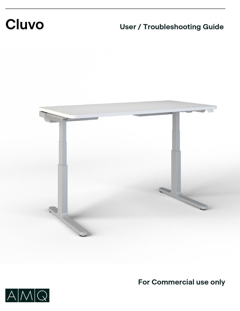
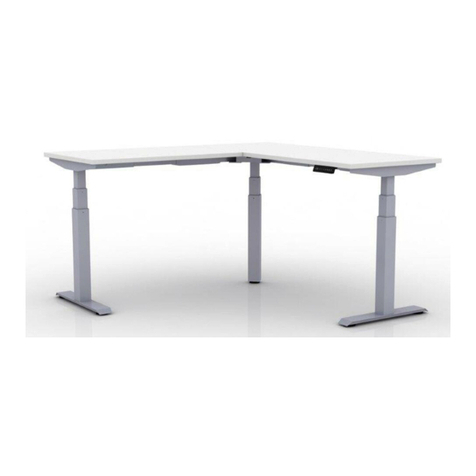
AMQ ACTIV-Pro User manual

ACTIV-PRO installation guide

ACTIV-PRO INSTALLATION GUIDE | 2 amqsolutions.com
COMPONENTS
M6*8
x 8 M10*30
x 8 ST 5*18
x 2 ST 5*20
x 18
8mm 5mm
Allen keys
4mm Screw caps x 8
Hardware
Leg columns x 2
Stretcher bar assembly
with control box
Cantilevers*x 2 Cantilevers*x 2
Foot*x 2
Controller cable x 1 Power cable x 1
LED control handset
x 1
*Feet and cantilevers are boxed separately.
Foot*x 2
T - Type C - Type
M6*10
x 8 Cable
Management
Clip

ACTIV-PRO INSTALLATION GUIDE | 3 amqsolutions.com
SAFETY STATEMENT
WARNING RISK OF SERIOUS INJURY DUE TO PINCH POINTS, TIPOVER, OR
POTENTIAL COLLAPSE.
This powered, adjustable height desk appliance is not intended for use by persons (including children) with
reduced physical, sensory or mental capabilities, or lack of experience and knowledge, unless they have
been given supervision or instruction concerning use of the appliance by a person responsible for their
safety. Children should be supervised to ensure that they do not play with the appliance.
• RISK OF DEATH OR SERIOUS
INJURY. Raising or lowering desk
cantrap, pinch or crush body parts or
property.
• CRUSH HAZARD - DO NOT PLACE
FEET, LEGS OR OTHER BODY
PARTS ON OBJECTS PLACED
UNDER TABLE TOP OR BELOW
MODESTY PANEL.
• DO NOT OPERATE THIS EQUIPMENT
Unless Properly Trained.
• DO NOT ALLOW USE BY CHILDREN
or people unable to understand the risks
and to safely adjust the desk height.
• INSPECT REGULARLY. Stop using if
product is damaged or has loose parts.
Only repair with AMQ authorized parts
and methods.
• MAINTAIN >1” (25mm) GAP ABOVE
OBJECTS ON DESK AT MAX HEIGHT
AND BETWEEN THE DESK &
ADJACENT OBJECTS. Locate desk,
accessories, and nearby objects to
allow movement of desktop through full range without pulling cords, trapping body parts, or colliding with anything
(shelves, electrical plugs and cords, door knobs, window sills, storage cabinets, etc.)
This device complies with part 15 of the FCC rules. Operation is subject to the following two conditions: (1) This device may not cause
harmful interference, and (2) this device must accept any interference received, including interference that may cause undesired
operation.
This equipment has been tested and found to comply with the limits for a class B digital device pursuant to Part 15 for FCC rules. These
limits are designed to provide reasonable protection against harmful interference in a residential installation. This equipment generates,
uses and can radiate radio frequency energy and, if not installed and used in accordance with the instructions, may cause harmful
interference to radio communications. However, there is no guarantee that interference will not occur in a particular installation. If this
equipment does cause harmful interference to radio or television reception, which can be determined by turning the equipment off and
on, the user is encouraged to try to correct the interference by one or more of the following measures: Reorient or relocate the receiving
antenna. Increase the separation between the equipment and receiver. Connect the equipment into an outlet or a circuit different from
that to which the receiver is connected. Consult the dealer or an experienced radio/TV technician for help.
Important: Changes or modifications to this product not authorized by AMQ could void your authority to operate the product.
Max.
Min.
>1"
(25mm)
>1"
(25mm)
>1"
(25mm)
X
X
X
NOTE: Desk image
is for reference only.
Table shape and leg
quantity may change
based on the style
and configuration.
(877) 801-0307
www.amqsolutions.com
?

ACTIV-PRO INSTALLATION GUIDE | 4 amqsolutions.com
WARNING
SAFETY STATEMENT
RISK OF SERIOUS INJURY:
POTENTIAL FOR INJURY: The use of worksurfaces that do not comply with the AMQ defined criteria and limitations
could cause personal injury or property damage due to pinch points, instability, or other problems.
POTENTIAL FOR NON-COMPLIANCE: The use of work surfaces that do not comply with AMQ criteria VOIDS any
AMQ claims of compliance with ANSI/BIFMA, UL, LEED, or other applicable requirements. The use of non-AMQ work
surfaces on AMQ adjustable-height bases may NOT be accepted as compliant to municipal electrical codes or OSHA
federal workplace standards, because this use does not create an NRTL (UL, ETL, etc.) listed product. AMQ is not
responsible for the ultimate determinations of compliance for height-adjustable bases with non-AMQ work surfaces.AMO
assumes NO liability for lack of standards compliance in these instances.
WARRANTY RESTRICTIONS: The use of non-AMQ supplied work surfaces VOIDS all AMQ warranties, expressed or
implied.
DISCLAIMER: The use of non-AMQ work surfaces is NOT recommended. Any use of a non-AMQ work surface
requires additional investigation by the customer regarding the appropriateness for use. It is the sole responsibility of
the customer to determine the suitability and safety of the selected work surface construction and attachment means.
The following information is provided as a guideline, but does not address all potential issues. Customers should seek
professional guidance as to the appropriateness of their chosen work surface.
MANDATORY REQUIREMENTS REGARDLESS OF WORK SURFACE MATERIAL OR CONSTRUCTION:
FASTENERS: Adjustable-height bases include fasteners intended for use with AMQ work surfaces.
These fasteners may potentially also be suitable for work surfaces meeting the following criteria:
• Medium-density or higher particleboard or fiberboard cores with High-pressure laminate (HPL), Lowpressure
laminate (LPL) or veneer & backers
• Thickness of .984” (25.0 mm) or greater
• Fasteners located a minimum distance of .984” (25.0 mm) from any edge
Any other work surface construction will require different and/or additional fastening means and these means must be
determined by the project’s designer, architect, or engineer. For example, solid-surface materials should use appropriate
threaded inserts and corresponding fasteners or
similar attachment means.
In all cases, all fastener locations provided in the
base attachment features MUST be used (e.g. if
attachment plate has 6 screw holes, all 6 holes
must be used for attachment).
FLAMMABILITY: Any worksurface or similar large
part> 10ft” 2 must have a flame spread< 200
and a smoke developed index < 450 when tested
per UL 723.
SHARP EDGES: All accessible edges of the
work surface must meet 1439 test for sharp
edges.
DIMENSIONAL LIMITATIONS:
• Work surface depth not to exceed
30”(762mm)
• Longitudinal work surface position on base
must be on centerline
• Maximum work surface width may not
exceed 72” (1828.8 mm)
• Work surface overhang (distance from side
of support cantilever to edge of work surface)
must be greater than .75” (19mm) and may not exceed 1.25” (32 mm)
FOLLOW ALL WARNINGS PROVIDED FOR BASE+ WORK SURFACE.
WORKSURFACE
OVERHANG
C
L
+
WORKSURFACE
WIDTH
WORKSURFACE
DEPTH

ACTIV-PRO INSTALLATION GUIDE | 5 amqsolutions.com
SAFETY INSTRUCTIONS
When using an electrical furnishing, basic precautions should always be followed, including the following:
Read all instructions before using (this furnishing). PLEASE SAVE THESE INSTRUCTIONS, AND THE USER
GUIDE, IN AN OBVIOUS PLACE FOR THE END USER AFTER ASSEMBLY.
1. Always unplug this furnishing from the electrical outlet before cleaning.
2. Use this table only for its intended use as described in these instructions.
Do not use attachments not recommended by the manufacturer.
3. Never operate this table if it has a damaged cord or plug, if it is not working
properly, or if it has been dropped or damaged.
4. Keep the cord away from heated surfaces.
5. Never drop or insert any object into any opening.
6. Do not use outdoors.
7. Do not operate where aerosol (spray) products are being used or where
oxygen is being administered.
8. For loading always put heavier items at the bottom and not near the top in
order to help prevent the possibility of the furnishing tipping over.
9. Do not sit/stand on product.
10. Inspect regularly, stop using if damaged or loose parts found.
The desk or table shall be installed near power socket & the plug shall
be easily accessible.
WARNING - Risk of fire and shock, Use only type SJT 18 AWG cord
POLARIZED PLUG INSTRUCTIONS (Only for products with polarized
plug) - To reduce the risk of electrical shock, some furnishings have a polarized
plug (one blade is wider than the other) like the plug illustrated in Figure 1. This
plug will fit in a polarized outlet only one way. If the plug does not fit fully in the
outlet, reverse the plug. If it still does not fit, contact a qualified electrician to
install the proper outlet. Do not change the plug in any way.
GROUNDING INSTRUCTIONS (for grounded products only) - Some
products must be grounded. Connect these appliances to a properly grounded
outlet in accordance with all local codes and ordinances. If a grounded outlet
is not available and cannot be installed, an adapter with ground screw must be
used as shown in Figure 2.
Improper connection of the equipment-grounding conductor can result in a risk
of electric shock. Check with a qualified electrician or serviceman if you are in
doubt as to whether the product is properly grounded. Do not modify the plug
provided with the product - if it will not fit the outlet, have a proper outlet installed
by a qualified electrician.
For products sold in North America and other 120v regions: the product is for
use on a normal 120-V circuit. These products use a grounding plug that looks
like the plug illustrated in sketch A in Figure 2. Make sure that the product is
connected to an outlet having the same configuration as the plug. No adapter
should be used with this product unless using the adapter with grounding screw shown in illustration.
PLUG ILLUSTRATION DISCLAIMER - The illustrations shown to the left show a plug typically seen in North
America and other 120V regions. Illustrations shown here may not match your product. Depending on
your region, the plug pin size and shape may change.
WARNING
GROUNDED
OUTLET
GROUNDED
OUTLET BOX
(A)
(B)
METAL
SCREW
ADAPTER
TAB FOR
GROUNDING SCREW
GROUNDING PIN
Figure 1
Polarized Plug
Figure 2
Grounding methods
Products with Grounded Plugs
Products with Polarized Plugs
DANGER

ACTIV-PRO INSTALLATION GUIDE | 6 amqsolutions.com
PHASE 1 | Preparing for Assembly
Step 1
Place Stretcher Bar unit upside down on work area.
Turn Stretcher Bar upside down
The label will face up when
Stretcher Bar is upside down
and ready to begin assembly.

ACTIV-PRO INSTALLATION GUIDE | 7 amqsolutions.com
PHASE 2 | Attaching Legs
Step 1
Slide leg columns into place and attach with M6 screws.
Match inside holes first and lightly tighten at this point.
Match inside holes first and
lightly tighten at this point.
M6 screws
use 5mm
allen key

ACTIV-PRO INSTALLATION GUIDE | 8 amqsolutions.com
PHASE 3 | Attaching Cantilevers
Step 1
Insert Cantilevers on each end, lifting the leg a
bit, if needed, to ease into a flush fit. Tab into
place (fit is snug).
M6 screws
use 5mm
allen key
Use screw
caps
Step 2
Using M6 screws, tighten all 4 holes lightly. Once
level, go back through and tighten each screw
completely. Place plastic caps over each screw.

ACTIV-PRO INSTALLATION GUIDE | 9 amqsolutions.com
PHASE 4 | Feet Assembly
Step 1
Attach feet using M10 socket screws. Match
all 4 holes first to confirm fit before tightening
completely.
M10 screws
use 8mm allen key

ACTIV-PRO INSTALLATION GUIDE | 10 amqsolutions.com
PHASE 5 | Adjusting Base Width
Step 1
Adjust to desired width. Use #4 allen key to loosen
the factory-inserted screws if not already loose.
IMPORTANT NOTE: Work surface overhangs
larger than .964” (25.0mm) are not allowed on
widths < 64.0” (1625.6mm)
Step 2
Once at correct width – and ensuring that centered
screw brackets are aligned – tighten all inset
screws.
Use 4mm allen key to
tighten pre-mounted
inset screws
Centered screw bracket
2
1

ACTIV-PRO INSTALLATION GUIDE | 11 amqsolutions.com
PHASE 6 | Worksurface Mounting
Step 1
To attach the worksurface, start by laying the
worksurface down on the floor with the top down.
Step 2
Lay the base assembly upside down on top of the
worksurface.
Step 3
Double check to ensure that the base is properly
positioned on the underside of the worksurface,
and then attach with wood screws.
NOTE: The worksurface should be center aligned
with the cantiliver depth and should have equal
amount of overhang on each end.`
ST 5*18 x 2
ST 5*20 x 18
for worksurface
ST 5*20 x 16
for worksurface
T - Type Cantilever C - Type Cantilever
Handset

ACTIV-PRO INSTALLATION GUIDE | 12 amqsolutions.com
PHASE 7 | Connecting Handset and Power
Step 1
Make sure that the Left motor plugs into the M1
port, and the Right motor plugs into the M2 port.
Step 2
Connect power plug after the motors and handset
are connected properly.
Handset
Right
motor
Left
motor
Connect each plug according to the drawing.
Orient yourself to the table assembly by facing
as a user to identify the left and right motors
Power
Power Right motor
Left motor Handset
Step 3
Reset the base by holding the down arrow button
until it reaches its lowest height.
Step 4
Attach the plastic cable management to desired
area to secure cables and wires.
Facing
Direction

ACTIV-PRO INSTALLATION GUIDE | 13 amqsolutions.com
PHASE 8 | Program Height Memory Presets
Step 1
To Program Up to 4 Presets: Use the up/down
arrows to find desired height, then press “M”
followed by the number 1, 2, 3 or 4.
Step 2
To Test Programmed Height: Use the up/down
arrows to adjust the table to a height other than
the preset height. Then push the number you
programmed to see if it automatically adjusts to
the height programmed in Step 1. You may need to
hold for 2-3 seconds to activate the base.
NOTE: If it does not adjust to the programmed
height, repeat Step 1 followed by Step 2.
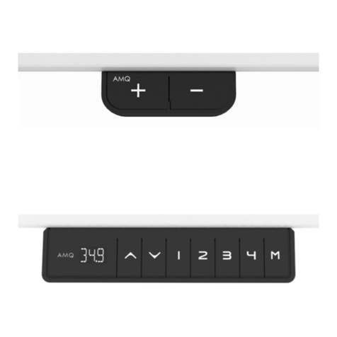
A
M
Q
1
2
3
M
4

ACTIV-PRO GUIDE D’INSTALLATION | 14 amqsolutions.com
COMPOSANTS
M6*8
x 8 M10*30
x 8 ST 5*18
x 2 ST 5*20
x 18
8mm 5mm
Clés Allen
4mm Cache-vis x 8
Quincaillerie
Colonne x 2
Jeu de barres de rallonge
avec boîte de commande
Support en porte-à-faux x 2 Support en porte-à-faux x 2
Patte x 2
Câble de
commande x 1
Câble de
commande x 1
Combiné de commande
DEL x 1
Patte x 2
T - Type C - Type
M6*10
x 8 Agrafe
de gestion
des câbles

ACTIV-PRO GUIDE D’INSTALLATION | 15 amqsolutions.com
ÉNONCÉ DE SÉCURITÉ
AVERTISSEMENT RISQUE DE GRAVES BLESSURES ATTRIBUABLES AUX POINTS
DE PINCEMENT, AU BASCULEMENT OU À L’EFFONDREMENT
Cette table de travail à réglage de la hauteur motorisé n’est pas destinée à être utilisée par des personnes,
notamment des enfants, dont les capacités physiques, sensorielles ou mentales sont réduites, ou qui n’ont
pas suffisamment de connaissance ou d’expérience, à moins qu’elles ne fassent l’objet d’une supervision
étroite ou qu’elles aient reçu des directives d’utilisation de la part d’une personne responsable de leur
sécurité. Il faut surveiller les enfants pour s’assurer qu’ils ne jouent pas avec cette table.
• RISQUE DE DÉCÈS OU DE GRAVE BLESSURE. Il existe un risque de piégeage, de pincement ou d’écrasement
de parties du corps ou d’objets au moment de lever ou d’abaisser le bureau.
• RISQUE D’ÉCRASEMENT - ÉVITEZ
DE METTRE LES PIEDS, LES
JAMBES OU TOUTE PARTIE DU
CORPS SUR LES OBJETS PLACÉS
SOUS LE DESSUS DE LA TABLE OU
SOUS LE CACHE-JAMBES
• N’UTILISEZ PAS CET ÉQUIPEMENT
à moins d’avoir suivi une formation
appropriée.
• NE CONFIEZ PAS L’UTILISATION
À UN ENFANT ni à une personne
incapable de comprendre le risque
couru et de régler la hauteur du bureau
en toute sécurité.
• INPECTEZ PÉRIODIQUEMENT.
CESSEZ d’utiliser le produit s’il est
endommagé ou si des pièces sont
devenues lâches. Réparez uniquement
au moyen de pièces et de méthodes
AMQ autorisées.
• CONSERVEZ UN DÉGAGEMENT DE
PLUS D’UN POUCE (25 mm) AU-
DESSUS DE TOUT OBJET SUR LE
BUREAU LORSQUE CE DERNIER
EST À LA HAUTEUR MAXIMUM AINSI QU’ENTRE LE BUREAU ET TOUT OBJET ADJACENT. Disposez le
bureau, les accessoires et les objets adjacents de manière à pouvoir faire bouger librement le bureau sans tirer sur
les cordons, piéger une partie du corps ou frapper des objets (tablette, fiche et cordon électrique, poignée de porte,
appui de fenêtre, armoire de rangement, etc.).
Important : Toute modification apportées à ce produit, non autorisées par AMQ, peut annuler votre droit d’utiliser le produit.
Max.
Min.
X
X
X
1 877 801-0307
?
POUR RÉFÉRENCE
POUR RÉFÉRENCE
POUR RÉFÉRENCE
REMARQUE : Images du
bureau à titre de référence
seulement. La forme de la
table et le nombre de pattes
peuvent varier en fonction
du style et de la
configuration.
> 1 po
(25 mm )
> 1 po
(25 mm )
> 1 po
(25 mm )
www.amqsolutions.com

ACTIV-PRO GUIDE D’INSTALLATION | 16 amqsolutions.com
RISQUE DE BLESSURE: L’utilisation de surfaces de travail non conformes aux critères et aux restrictions établis par AMQ
peut causer des blessures ou des dommages matériels attribuables aux points de pincement, à l’instabilité ou à d’autres
problèmes
RISQUE DE NON-CONFORMITÉ: L’utilisation de surfaces de travail non conformes aux critères établis par AMQ ANNULE
toute représentation de conformité de la part d’AMQ concernant les exigences ANSI/BIFMA, UL, LEED et concernant toutes
autres exigences applicables. L’utilisation de surfaces de travail non fabriquées par AMQ avec les bases à hauteur réglable
d’AMQ pourrait NE PAS être considérée comme conforme aux codes de l’électricité municipaux ou avec les normes fédérales
de l’OSHA concernant les lieux de travail, parce qu’une telle utilisation fait en sorte qu’il s’agit d’un produit non homologué
UL, ETL, etc. (produit NRTL). AMQ n’est pas responsable de déterminer en fin de compte la conformité des bases à hauteur
réglable dotées d’une surface de travail dont elle n’est pas le fabricant et, à cet égard, n’assume AUCUNE responsabilité pour
la conformité de tels éléments aux normes.
RESTRICTIONS EN MATIÈRE DE GARANTIE: L’utilisation d’une surface de travail non fabriquée par AMQ ANNULE toutes
les garanties AMQ, explicites et implicites.
AVIS DE NON-RESPONSABILITÉ: L’utilisation de surface de travail non fabriquée par AMQ n’est PAS recommandée.
L’adéquation de l’utilisation d’une surface de travail non fabriquée par AMQ doit faire l’objet d’une étude approfondie de la part
du client. La détermination de l’adaptation et de la sécurité de la surface de travail et des éléments de fixation choisis relèvent
de la seule et unique responsabilité du client. L’information qui suit est destinée uniquement à servir de guide et ne traite pas
tous les problèmes pouvant potentiellement survenir. Le client doit demander l’avis d’un professionnel quant à l’adéquation de
la surface de travail choisie.
EXIGENCES OBLIGATOIRES SANS ÉGARD AUX MATÉRIAUX OU À LA FABRICATION DE LA SURFACE DE TRAVAIL:
ÉLÉMENTS DE FIXATION: Les bases à hauteur réglable comprennent des éléments de fixation conçus pour les surfaces de
travail AMQ. Ces éléments de fixation PEUVENT aussi convenir aux surfaces de travail conformes aux critères suivants:
• Panneaux de particules ou de fibre de bois de densité moyenne ou supérieure avec stratifié haute pression (HPL), stratifié
basse pression (LPL), placage et planches d’appui.
• Épaisseur d’au moins 25 mm (0,984 po)
• Les éléments de fixation doivent être situés à au moins 25,0 mm (0,984 po) du rebord.
Une surface de travail fabriquée de tout autre matériau ou selon toute autre méthode exige des éléments de fixation différents
ou supplémentaires, selon ce que détermine le concepteur du projet, l’architecte ou l’ingénieur. Par exemple, avec des
matériaux pleins ou rigides, il faut utiliser des douilles filetées ainsi que des éléments ou des moyens de fixation correspondants
appropriés.
Dans toutes les situations, IL FAUT se servir des éléments de fixation prévus dans la base (p.ex., si l’élément
de fixation comporte six trous pour des vis, il faut
se servir des six trous pour la mise en place).
INFLAMMABILITÉ: Toute surface de travail ou
grande pièce similaire > ^ 2 doit avoir un indice
de propagation des flammes < 200 et un indice
de d’émission de fumé < 450 lors de tests
conformes à la norme UL 723.
ANGLES VIFS: Tous les angles de la surface de
travail doivent réussir le test 1439 pour ce qui est
des angles vifs.
LIMITES DIMENSIONNELLES :
• La profondeur maximum de la surface de
travail est de 30.0” (762 mm)
• Le centre de la surface de travail doit être
placé au centre de la base
• La largeur maximum de la surface de travail
ne doit pas excéder 72” (1828.8 mm)
• Le porte-à-faux de la surface de travail
(distance entre le côté du support et le
rebord de la surface de travail) doit être
supérieur à .75” (19mm), mais inférieur à
1.25” (32 mm)
RESPECTEZ TOUS LES AVERTISSEMENTS
DONNÉS POUR LA BASE ET LA SURFACE DE
TRAVAIL.
AVERTISSEMENT RISQUE DE GRAVES BLESSURES!
ÉNONCÉ DE SÉCURITÉ
C
L
+
LARGEUR DE LA
SURFACE DE
TRAVAIL
PROFONDEUR DE LA
SURFACE DE TRAVAIL
PORTE-À-FAUX
IMAGES DU BUREAU
À TITRE DE RÉFÉRENCE
SEULEMENT. LA FORME
DE LA TABLE ET LE NOMBRE
DE PATTES PEUVENT VARIER
EN FONCTION DU STYLE ET
DE LA CONFIGURATION.

ACTIV-PRO GUIDE D’INSTALLATION | 17 amqsolutions.com
IMPORTANTES DIRECTIVES DE SÉCURITÉ
LORS DE L’UTILISATION DE MOBILIER ÉLECTRIQUE, IL FAUT TOUJOURS PRENDRE DES PRÉCAUTIONS DE
BASE, NOTAMMENT : LISEZ TOUTES LES DIRECTIVES AVANT DE VOUS SERVIR DE (CE MOBILIER). LAISSEZ LES
DIRECTIVES ET LE GUIDE DE L’UTILISATEUR À LA VUE, À L’INTENTION DE L’UTILISATEUR, APRÈS L’ASSEMBLAGE.
1. Débranchez toujours le mobilier de la prise électrique avant de le nettoyer.
2. Utilisez uniquement cette table aux fins décrites dans les présentes directives.
N’utilisez pas d’éléments d’appoint non recommandés par le fabricant.
3. N’utilisez jamais cette table si le cordon ou la fiche est abîmée, si elle ne fonctionne
pas correctement, si elle a chuté ou a été endommagée.
4. Gardez le cordon à l’écart des surfaces chauffées.
5. Ne laissez jamais tomber des objets dans les ouvertures et n’y insérez aucun objet.
6. N’utilisez pas à l’extérieur.
7. Ne faites pas fonctionner dans un endroit où des produits en aérosol (vaporisateur)
sont utilisés ou encore là où de l’oxygène est administré.
8. Lorsque vous y placez des objets, placez toujours les objets les plus lourds dans le
bas, non pas près du dessus, pour éviter tout risque de basculement du mobilier.
9. Évitez de vous asseoir ou de monter sur le produit.
10. 10. Inspectez régulièrement le produit et cessez de vous en servir si vous décelez
des pièces lâches ou endommagées.
Le bureau ou la table doit être installé près de la prise de courant et la fiche
doit être facilement accessible.
AVERTISSEMENT – Risque d’incendie et de choc, l’utilisation seul type SJT 18
AWG cordon
DIRECTIVES RELATIVES À LA FICHE POLARISÉE (Uniquement pour les
produits avec fiche polarisée) - Pour réduire les risques d’électrocution, certains
meubles sont dotés d’une fiche polarisée (l’une des lames est plus large que l’autre),
comme la fiche illustrée dans la Figure 1. Cette fiche s’insère d’une seule manière dans
une prise polarisée. Si la fiche ne s’enfonce pas complètement dans la prise, inversez
le sens d’insertion. Si cela ne fonctionne toujours pas, communiquez avec un électricien
qualifié pour installer une prise électrique polarisée. Ne modifiez pas la prise d’aucune
manière.
DIRECTIVES DE MISE À LA TERRE (Uniquement pour les produits mis à la
terre) - Certains produits doivent être mis à la terre. Branchez ces appareils dans
une prise correctement installée et mise à la terre, conformément aux codes locaux et
nationaux en vigueur. Si vous n’avez pas de prise mise à la terre et s’il est impossible
d’en installer une, vous devez utiliser un adaptateur avec vis de mise à la terre, comme
illustré dans la Figure 2.
Le raccordement inapproprié du conducteur de mise à la terre du mobilier pourrait
accroître les risques d’électrocution. Consultez un électricien qualifié ou un technicien
d’entretien en cas de doute quant à la mise à la terre appropriée du mobilier. Ne
modifiez pas la fiche dont est doté le produit; si vous n’arrivez pas à l’insérer dans
la prise électrique, communiquez avec un électricien qualifié pour installer une prise
électrique appropriée.
Les produits vendus en Amérique du Nord et dans les régions où la tension secteur est de 120 V un circuit d’une
tension nominale de 120 V. Ces produits sont dotés d’une fiche avec broche de mise à la terre comme celle illustrée
ans le dessin A de la Figure 2. Assurez-vous que le produit est branché à une prise de configuration identique à la fiche.
N’utilisez pas d’adaptateur avec ce produit, à moins que ce soit un adaptateur doté d’une vis de mise à la terre comme
celui indiqué dans l’illustration.
AVIS DE NON-RESPONSABILITÉ POUR L’ILLUSTRATION DE LA FICHE - L’illustration à gauche montre une
fiche classique utilisée en Amérique du Nord et dans les régions où la tension secteur est de 120 V. Les illustrations
du guide pourraient ne pas correspondre à votre produit. Selon la région, la taille et la forme des broches pourraient
varier.
DANGER
AVERTISSEMENT
BOÎTE MISE À
LA TERRE
BOÎTE MISE
À LA TERRE
(A)
(B)
VIS
MÉTALLIQUE
ADAPTATEUR
TIGE POUR VIS
DE MISE À LA TERRE
BROCHE DE
TERRE
(Dessin A)
Figure 1
Fiche polarisée
Figure 2
Méthodes de mise à la terre
Produits avec fiche mise à la terre
Produits avec fiche polarisée

ACTIV-PRO GUIDE D’INSTALLATION | 18 amqsolutions.com
PHASE 1 | Préparer l’assemblage
Step 1
Placez la barre de rallonge à l’envers sur la surface de travail.
Retournez la barre de rallonge à l’envers
L’étiquette sera vers le haut lorsque la barre de
rallonge est à l’envers et prête à être mise en place.

ACTIV-PRO GUIDE D’INSTALLATION | 19 amqsolutions.com
PHASE 2 | Attacher les pattes
Step 1
Glissez les colonnes des pattes en place et fixez-les au
moyen de vis M6*8. Alignez d’abord les trous internes,
puis serrez légèrement.
Alignez d’abord les trous internes,
puis serrez légèrement.
Vis M6*8
Utilisez une clé
Allen de 5 mm

ACTIV-PRO GUIDE D’INSTALLATION | 20 amqsolutions.com
PHASE 3 | Attacher en porte-à-faux
Step 1
Insérez les supports en porte-à-faux à chaque
extrémité, en soulevant un peu la patte, au
besoin, pour faciliter un bon ajustement.
Poussez en place (en vous assurant que
l’ajustement est parfait).
Vis M6*8
Utilisez une clé
Allen de 5 mm
Utilisez les
cache-vis.
Step 2
Au moyen de vis M6*8, serrez légèrement dans
les 4 trous. Une fois au niveau, revenez au début
et serrez complètement chaque vis. Placez un
cache-vis de plastique sur chaque vis.
Other manuals for ACTIV-Pro
2
Table of contents
Languages:
Other AMQ Indoor Furnishing manuals
Popular Indoor Furnishing manuals by other brands

KidKraft
KidKraft ULTIMATE SPACESHIP Flight manual

LOUNGELOVERS
LOUNGELOVERS ARCHER manual

Kohler
Kohler 2451 Installation and user guide

Furniture of America
Furniture of America CM3146H Assembly instructions

Polini kids
Polini kids Simple manual

FMD Furniture
FMD Furniture BANDOL 1 668-001 Assembly instruction

Furniture of America
Furniture of America CM3736-PBN Assembly instructions

Home Decorators Collection
Home Decorators Collection MERRYFIELD 19112-VS49-AG Assembly instructions

Baxton Studio
Baxton Studio King Bed 0050 Assembly instructions

Casa Lusso
Casa Lusso eden installation instructions

LAZBOY
LAZBOY D71 M80905 Use and care guide

Costway
Costway JV11305 manual