Anatomic SITT Zitzi Active User manual

2020-07-02
EN
User manual
Zitzi Active

2User manual Zitzi Active www.anatomicsitt.com | +46 11 16 18 00
Table of contents
Safety precautions ........................................3
Tool........................................................................4
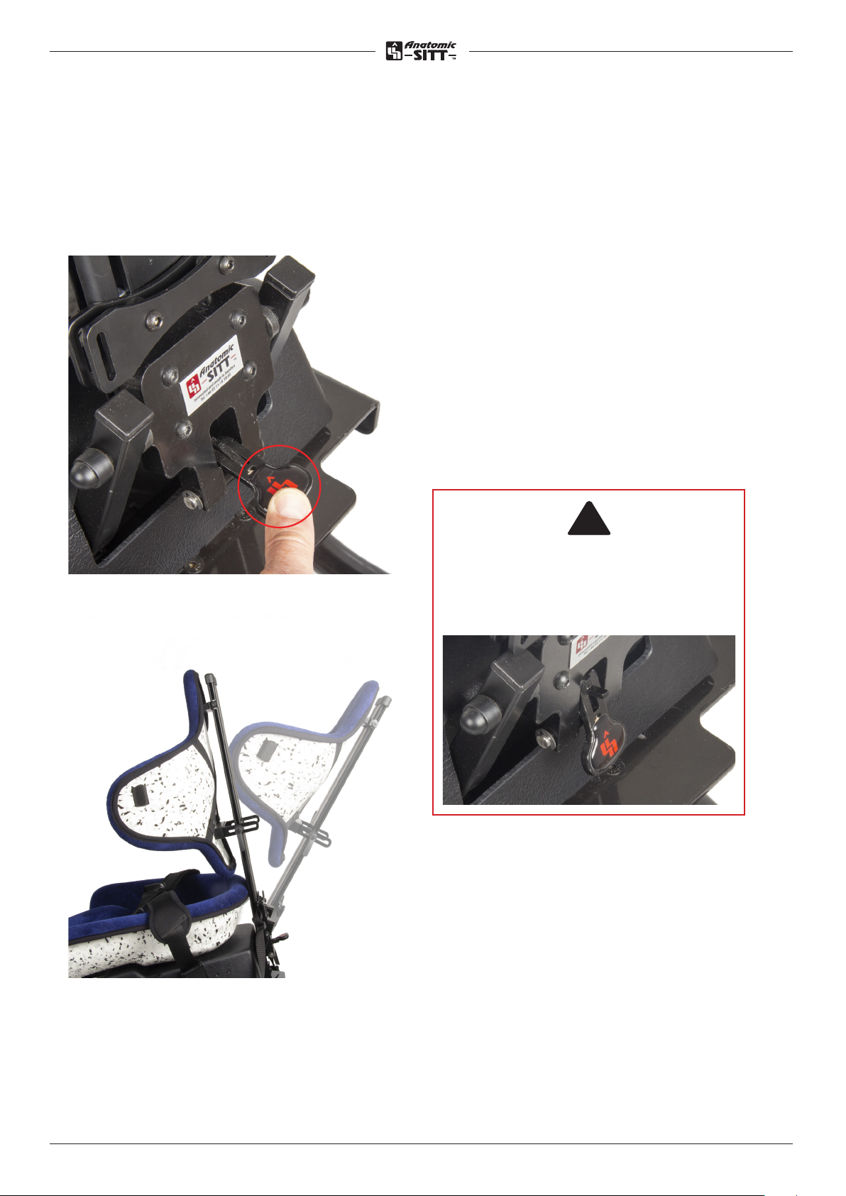
Mounting/dismantling back......................4
Back angle adjustment................................5
Back height adjustment..............................6
Back adjustment in depth..........................6
Adjustment of seat position .....................7
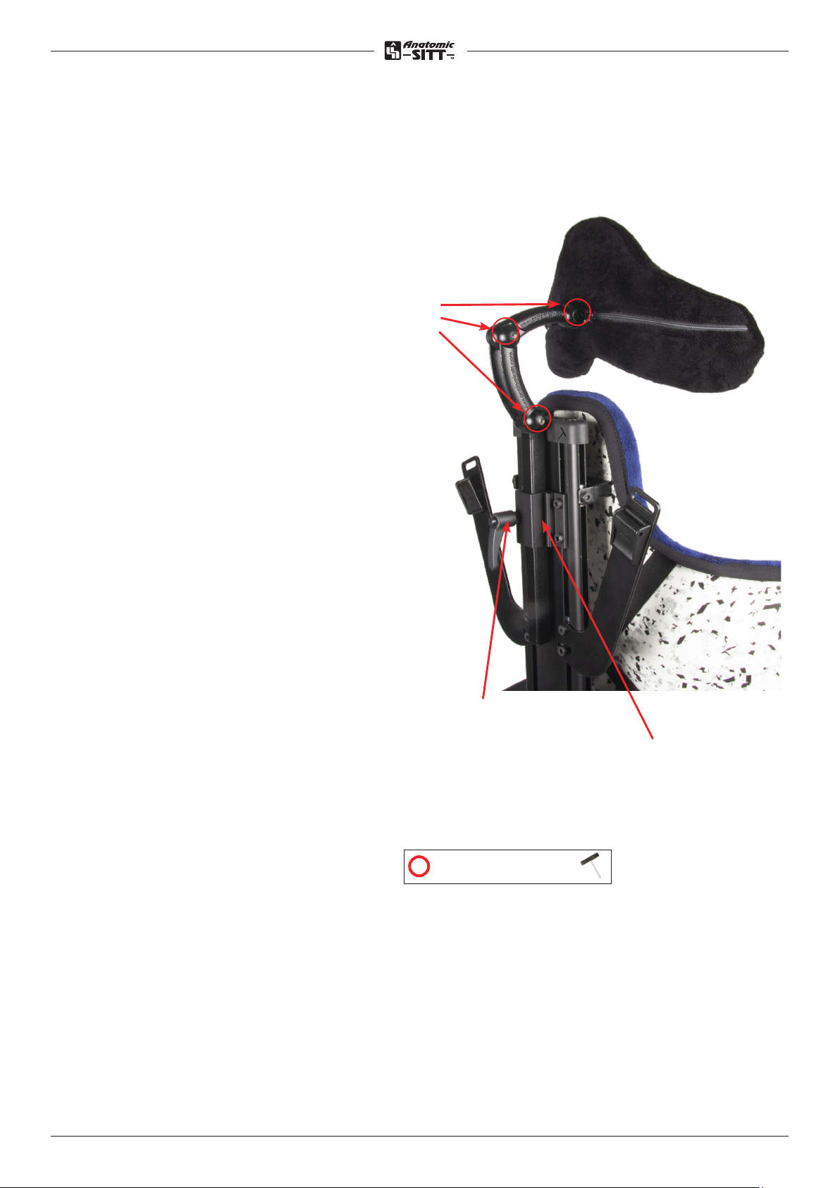
Headrest .............................................................8
Hipbelt.................................................................9
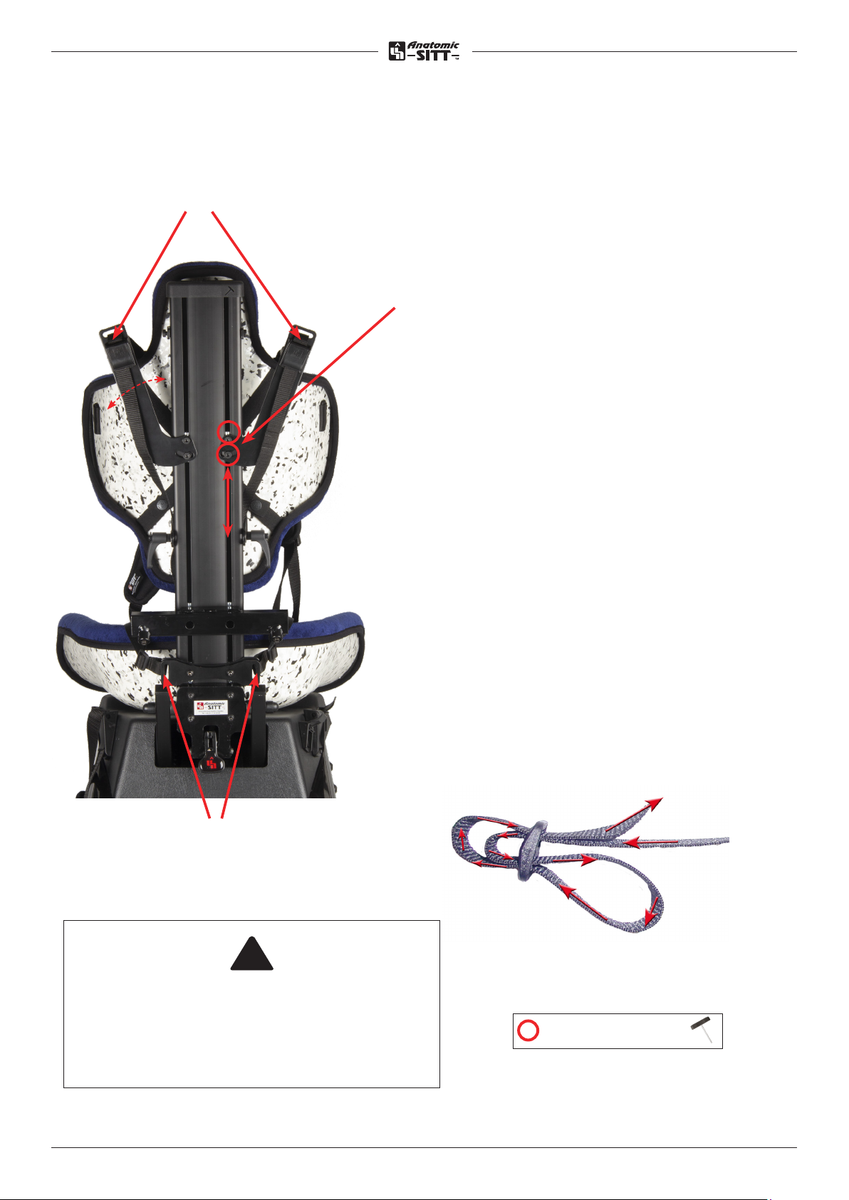
Chest harness.................................................10
Chestbelt............................................................11
Armrest from back .......................................12
Rest handle ..................................................... 13
Knee support.................................................. 14
Check the check box if the product
is CUSTOMIZED.
The CE Mark is no longer valid and
should be removed.
Place of label
This product is manufactured by Anatomic SITT AB
Postal address Anatomic SITT AB, Box 6137, SE-600 06 Norrköping
Street address Anatomic SITT AB, Terminalgatan 1, SE-603 61 Norrköping
Phone +46 11-161800
Fax +46 11-162005
Email info@anatomicsitt.com
Webb anatomicsitt.com
Instructions movies youtube.com/anatomicsitt
Follow us on facebook.com/anatomicsitt
Support table................................................. 15
Driving bow..................................................... 15
Footrest, whole ............................................. 16
Footrest, divided joint.................................17
Calf support.................................................... 18
Foot strap ........................................................ 19
Ankle holder ................................................... 19
Underframe Flipper Pro G2....................20
Underframe Seastar................................... 22
Maintenance instructions ........................ 23
Summary and follow-ups........................ 24
Adaptation and customization............. 25
Terms of sale ................................................. 26
Technical data................................................27

3User manual Zitzi Active www.anatomicsitt.com | +46 11 16 18 00
Introduction
In order to use the Zitzi Active in its full extent, it is important that you read this
manual. This applies to everyone close to the user.
The product is intended for users with seating problems and fits many dierent
kinds of diagnoses. Adaptation/fitting of Zitzi Active must be done by a medically
qualified person.
If you need additional information, please contact Anatomic SITT AB.
Field of application
The product is only intended for use as a active seating system together with
chassis produced by Anatomic SITT AB.
Zitzi Active is a complement to the regular seating system and the time for active
sitting should be limited based on the patient’s conditions. When using Active
together with Flipper/Flipper G2 or Flipper Flex/G2 must frame extension be
mounted due to tip risk.
Control before use
Check all moving parts, belts and fasteners regarding wear, function etc. Also check
that the plastic parts are intact and free of damage. Check that the seating system
is correct attached to the chassis. When using Zitzi Active, one of our hip belts
should always be used and also a chest belt or chest harness if necessary (follow
the instructions in the respective product user manual).
Never leave the patient unattended in the Active chair and pay attention to any
problems for the patient.
Safety strap
A safety strap is delivered to the seating system which should always be used
together with the universal adapter system. This strap should be tensioned from the
seat back profile and around the chassis drivingbow/ -handle. Make sure that this
strap sits stable and tight.
Control after use
Always check after use to detect redness or pressure marks on the patient.
Correspondence
Zitzi Active and its accessories are CE marked products. A unique serial number is
located on a label placed under the lining of the seatingpart.
This serial number should be quoted in any correspondence regarding the product.
Safety precautions
!!
!!
!!
!!

4User manual Zitzi Active www.anatomicsitt.com | +46 11 16 18 00
Tool
The allen key (4 mm) is integrated in
the top of the back and can be used
to make adjustments.
!!
The tool should be in the profile
when it is not used to protect the
top of the back profile.
It also comes with a
Torx key T-25
Mounting/dismantling the back
The backrest is mounted with 4 bolts.
Insert the back profile down into the
socket pins and tighten the four screws
provided (red in the picture).
The back will automatically be in the
right place, using the stop in the back
profile.
= Torx key
= Adjustment bolts

5User manual Zitzi Active www.anatomicsitt.com | +46 11 16 18 00
Back angle adjustments
To activate the lever, pull it straight out
and then up. To adjust the angle of the
back, push the lever downwards, then
the back will be released so that you
can set it to the desired position. When
you reach the desired angle, release the
lever again.
It is very important that the lever is in
the safety mode, resting downwards,
when the adjustments are done.
!
!

6User manual Zitzi Active www.anatomicsitt.com | +46 11 16 18 00
Back height adjustments
• Loosen the skrews A and knobs B
according to pic. on both sides of
the back profile.
• Adjust the height.
• Position the back so that you use
the backrest’s integrated lumbar
support.
• Lock the screws and knobs.
A
Back depth adjustment
B
B
• Release the knob B (see pic)on
both sides of the back profile.
• Adjust the back depth C to the
desired depth.
• Lock the knob.
C
= Adjustment bolt

7User manual Zitzi Active www.anatomicsitt.com | +46 11 16 18 00
Adjustment of seat position
Shifting of the seat part
The seat part has two positioning
options: standard mount (position
1) or rear position (position 2). The
dierence is that the seat part is
moved 2.5 cm backwards in position 2.
To change between the two positions
loose the four screws and move the
seat to the new position.
Tighten the screws properly.
Position 1
Position 2
Seatslope pillow
Edge padding
Adaptation with edge padding
The edge padding can be removed completely or partially if you want more space
in the seat. It is fitted with velcro and can therefore easily be removed and then
repositioned.
If you want a trimmed edge padding, it can easily be cut to the desired length.
Adaption with seatslope pillow
The seatslope pillow can also be removed, sanded or replaced with other material.

8User manual Zitzi Active www.anatomicsitt.com | +46 11 16 18 00
Headrest bracket, 4
bolts with pins
A - Mounting of the headrest bracket
Begin with take away the integrated allen
key that originally is placed in the top of
the back profile.
Then push the headrest bracket (A) to
desired position in the track of the back
profile. Tighten the bolts!
B - Mount the headrest in the headrest
bracket (A) and adjust to desired position
is reached. Tighten the knob (B).
C - Adjusting the headrest
Loosen the adjustment bolts (C) a bit so
you can easily adjust with just your hands.
When desired position is reached, tighten
the bolts (C).
If the headrest need to be higher, loosen
the knob (B) and then adjust the headrest
into to desired position. Tighten the knob
(B).
Height adjustment knob
Headrest
C
A
B
= Adjustment bolts

9User manual Zitzi Active www.anatomicsitt.com | +46 11 16 18 00
Adjustment of hipbelt bracket
To move the position of the hip belt attachment, loosen the screw (A) and move
the buckle (B) to the desired position (see alternative holes behind the cover).
Insert screw (A) and tighten.
Mounting the hipbelt
Thread the hipbelt through the slot in the seat (C) and down through the buckle
(B). Pinch the belt strap firmly into the buckle (B).
Hipbelt
A
Alt. holes
B
D
B
Adjustment for antirotation belt
attachment
To move the position of the belt
attachment, loosen the screws (A) and
move the buckles (B + D) to the desired
position (see alternate holes). Insert the
screws (A) and tighten.
Mounting of antirotation belt
Thread both straps through the slot
in the seat (C) and down through the
buckle (B) and (D). Clamp the belt
straps firmly into the buckles.
C
= Torx key

10User manual Zitzi Active www.anatomicsitt.com | +46 11 16 18 00
Chest harness
Mounting, upper mounting bracket - A
Begin with take away the integrated allen
key that originally is place in the top of the
back profile. Then push the upper mounting
brackets (A) to desired position in the track
of the back profile.
Adjustments of the upper mounting
brackets
Loosen the bolts and make desired
adjustments. The height of the upper
mounting brackets should be place so that
the pull direction is a bit above the shoulder
area. Tighten the bolts.
Mounting of harness
Pull the strap through the track and into
the buckle. Then thread the harness lower
attachment points into the lower bracket
(B). Use attached Tri-glide buckles (E).
Adjusting the pull direction and width
Loosen the bolt of the upper mounting
bracket and adjust to desired height.
Tighten the upper bolt.
Adjust the angle to desired position and
tighten the bolt.
Upper mounting bracket
Lower brackets included 1
piece as standard
Be sure that there is enough space for the
neck, that the cushions are in the right
place and that the pressure is correct!
!!
A
B
E
= Adjustment bolts

11User manual Zitzi Active www.anatomicsitt.com | +46 11 16 18 00
Chest belt
Mounting chest belt
Mounting of the straps to the chest
harness is done by pulling the strap
through the trunk support as shown
in the figure to the right.

12User manual Zitzi Active www.anatomicsitt.com | +46 11 16 18 00
Mounting of armrests from back
Before mounting the armrests from the back, you must first remove the allen key
and possibly other details that are mounted already. These details may include a
headrest, upper mounting brackets and driving bow.
Loosen the stop screws (A) and move away the armrests (B) to access the screws
(C) through the holes in the bracket. Loosen the screws (C) enought to slide the
rail pins (D) in the tracks of the back profile. Adjust the bracket to desired height
before tightning the screws (C). Adjust the armrests (B) to desired widht and
tighten the stop screws (A).
Reassemble the details you removed before mounting the armrest bracket.
Armrest from back
Height adjustment
To adjust the height of the armrest, loosen
the screws (C). (The armrests may need to
be width-adjusted to the sides first if they
block the holes for the height adjustment).
Then adjust to desired height. Tighten the
screws.
Width adjustment
To adjust the width of the armrest, loosen the
stop screws (A) and then adjust to desired width.
Tighten the screws.
Adjusting the angle up/down
To adjust the angle of the armrest, loosen the le-
ver handle (E) and move the armrest to the desi-
red angle, then tighten lever handle (E).
Adjusting the lateral angle
To adjust the lateral angle of the armrest, loosen
the screws (F) and move the
armrest to the desired angle, then tighten the
screws (F).
F
A
B
D
E
C

13User manual Zitzi Active www.anatomicsitt.com | +46 11 16 18 00
Rest handle
B
C
A
Mounting of rest handle
Mount the rest handle (A) in the middle-
attachment (B) (square tube). Lock the
rest handle with the screw (C).
Adjusting the angle of rest handle
Loosen knob (D) and then adjust to the
desired angle. Lock the knob when the
desired angle is reached.
Important - After adjusting, the tags
must be interlocked to lock. Tighten the
knob hard!
!!
D

14User manual Zitzi Active www.anatomicsitt.com | +46 11 16 18 00
Knee support
Mounting of the knee support
The knee support is mounted with the
help of the plastic tag straps on each
side of the seat. The brackets for the
knee support can be placed high or
low (see pictures below).
• Mounting (low) in the lower part
takes place with the screws in the
existing holes as shown in Figure 1.
• Mounting (high) in the seat takes
place with the mounting kit (short
screws and plate) in existing holes in
the seat part as shown in Figure 2-3.
2. High placement - knee support
1. Low placement - knee support
3.
Adjustment of the knee support
The knee support can be clamped with
the practical buckle which has a built-in
clamping arm and release button.
Release
button
Clamping-
arm

15User manual Zitzi Active www.anatomicsitt.com | +46 11 16 18 00
Mounting the table
Put the table on the armrest plates and then rotate the locking levers (A) of the
table into position below the armrest plate (B). The locking lever must be rotated
until they reach the edge of the armrest plate.
The locking arms should be turned until they reach the edge of the armrest plate.
Support table
B A
1) Take away the allen key from the top of the back profile.
2) Mount the pins (A) in the tracks of the back profile.
3) Tighten screws when desired position is reached.
A
Driving bow

16User manual Zitzi Active www.anatomicsitt.com | +46 11 16 18 00
Footrest whole
Mounting the footrest
Mount the footrest in the square tube
(A). Secure the footrest with the locking
screw (B).
Adjusting the knee joint
Loosen the knob (C) and adjust to
desired position. Tighten when desired
positions is reached.
Important - The tags have to fit with each
other. Lock the bolt properly!
Height adjustment, foot plate
Loosen the lever handle (D), on both stay,
and adjust to desired position. Tighten
when desired positions is reached.
Angle adjustment, foot plate
Loosen screw (E) (both stays), nd adjust
to desired position. Tighten screws when
desired position is reached.
Important! - After adjusting, the tags
must be interlocked to lock.
A
B
C
D
E
!!
!!
= Adjustment bolts

17User manual Zitzi Active www.anatomicsitt.com | +46 11 16 18 00
Mounting the footrest
Mount the footrest in the square tube (A).
Secure the footrest with the locking
screw (B).
Adjusting the knee joint
Loosen the lever handle (C) and adjust
to desired position. Tighten when desired
positions is reached.
Important - The tags have to fit with each
other. Lock the knob properly!
Height adjustment, foot plate
Loosen the lever handle (D), and adjust
to desired position. Tighten when desired
positions is reached.
Angle adjusting, foot plate
Loosen screws (E) for foot plate and
adjust to desired angle. Tighten screws
propertly.
Divided footrest, joint
A
B
C
D
E
!!
= Adjustment bolts

18User manual Zitzi Active www.anatomicsitt.com | +46 11 16 18 00
Mounting of calf support
Remove the pipe cover at the bottom and unscrew the end stop. Remove the
stop and foot plate from the stay. Insert the calf support bracket’s socket pins
on the outside of the sides, as shown below. Tighten the screws (A). Attach the
calf support plate as shown in the figure below with the attached screw joints
(B).
Reassemble the footplate, end stop and pipe cover.
Height / depth adjustment - calf support
Loosen the screws (A), then adjust the calf plate to the desired height and
depth. Lock the screws (A).
Side-/angle adjustment - calf support
Loosen the screws (B) a little, then adjust the calf plate sideways
and angle. Tighten the screws (B).
A
B
Calf support
= Adjustment bolts

19User manual Zitzi Active www.anatomicsitt.com | +46 11 16 18 00
The footplate is prepared for mounting of the ankle holder.
Mountening of ankle holders on a whole adjustable and divided adjustable footrest
are made underneath the footrest.
Be sure that the pad not folded on the ankle holder.
!!
Ankle holder
The footplate is prepared for mounting the foot strap.
Mounting the foot straps on all footplates is done by pulling the strap down and up
through two of the appropriately pre-drilled holes in the footplate. The foot strap
can be mounted in the front or rear sets of holes.
Foot strap
alt. hole

20User manual Zitzi Active www.anatomicsitt.com | +46 11 16 18 00
Indoor underframe Flipper Pro G2
Fixed mounting
Fixed mounting means attaching the seating system directly to the underframe.
Installation using this method must be done with the supplied mounting kit.
At the bottom of the seating system you find holes for fixed mounting.
M6 Nut (C)M6 Screw (A)
4 st4 st
M6 Washer (B)
4 st
NOTE! Never use any screws other than the supplied screws. These
are security details. If other dimensions are desirable, contact
Anatomic SITT AB.
Table of contents
Other Anatomic SITT Wheelchair manuals

Anatomic SITT
Anatomic SITT Zitzi Starfish Pro User manual

Anatomic SITT
Anatomic SITT Zitzi Seabass Pro User manual

Anatomic SITT
Anatomic SITT Zitzi Sharky Pro User manual

Anatomic SITT
Anatomic SITT Zitzi Flipper Pro User manual

Anatomic SITT
Anatomic SITT Zitzi Delfi Pro User manual

Anatomic SITT
Anatomic SITT Zitzi Flipper Pro Flex User manual
Popular Wheelchair manuals by other brands

Care & Independence
Care & Independence COMFORT VALUE CVSC/ATT user guide

Whirlwind
Whirlwind RoughRider Assembly manual

Meyra
Meyra 1.835 operating manual

Invacare
Invacare NXT Generation NEXT user manual

Drive DeVilbiss Healthcare
Drive DeVilbiss Healthcare DSF 130 Instructions for use

Invacare
Invacare Spree XT Specifications