ANCEL HD Series User manual

HD Series
1
CONTENTS
PRODUCT OVERVIEW....................................................... 3
PRODUCT STRUCTURE .................................................... 4
HOST CONFIGURATION .................................................. 5
PRINTER CONFIGURATION (OPTIONAL) .................... 6
POWER ON/OFF ................................................................ 6
1) Power on
..........................................................................6
2) Power off
..........................................................................7
VEHICLE DIAGNOSTIC PREPARATION......................... 7
INTRODUCTION OF EACH FUNCTION MENU .........10
DIAGNOSTIC FUNCTION...............................................12
DPF REGENERATION ......................................................17
SERVICE RESET .............................................................18
PIN DETECT ...................................................................18
DATA MANAGEMENT ................................................19
DIAGNOSTIC SOFTWARE UPGRADE ......................20
SETTINGS .......................................................................21
14.1 Wi-Fi Connection ............................................................... 21
14.2 Brightness ............................................................................. 21
14.3 Volumes................................................................................. 22
14.4 User Information and Activation................................... 22
1) Activation
....................................................................... 22
2) User Info
........................................................................ 23

HD Series
2
14.5 Storage................................................................................... 24
14.6 General................................................................................... 24
1) Language
...................................................................... 24
2) Unit
................................................................................... 25
3) Date&Time
.................................................................... 25
4) About
............................................................................... 26
5) Reset
............................................................................... 26
PRINTER INTRODUCTION .........................................27
1) Printer combination and split
................................. 27
2) Printer loading and changing paper
................... 27
3) Printer self-test function
.......................................... 28
FAQ (FREQUENTLY ASKED QUESTIONS) ...............29

HD Series
3
Product Overview
ANCEL HD series products are commercial vehicle diagnostic
tools based on special Android tablet.
This product integrates commercial vehicle OBD standard
diagnostic protocols, including SAE J1939, SAE J1708, SAE
J1850 PWM, SAE J1850 VPW, ISO 14230-4, ISO 9141-2, ISO
15765-4 and ISO 27145-4. The commercial vehicles are
classified according to the vehicle type information, and the
operation interface is very clear, which makes it convenient for
users to diagnose commercial vehicles.
There’s an optional printer module available to have diagnosis
data and report printed. At the same time, the product supports
online upgrade of diagnostic program and diagnostic data.

HD Series
4
Product Structure

HD Series
5
Serial No. Name Function Description
①Main Testing
Cable
Connection interface connects
vehicle communication cable during
vehicle diagnosis
②USB Port Used to connect to an external
computer
③Print Used to print diagnostic reports and
results
④Paper bin
cover
After opening, you can install and
replace the printing paper
⑤Touch
screen
Display content and touch operation
area
⑥Speaker Device sound output
⑦Auxiliary
bandage Auxiliary for hand holding
⑧Separation
switch Host and printer separation switch
⑨Test key Printer self-test and paper feed
button
⑩Paper outlet Printer paper outlet
Host Configuration
CPU Quad-Core ARM Cortex-A7
RAM 1GB
Flash 8GB
Display 5 inches LCD, resolution ratio 800*480

HD Series
6
TP touch screen Capacitive screen
WIFI 802.11b/g/n 2.4GHz
Horn Support
USB interface Type C interface
Diagnose
interface DB15 interface
Operating
voltage DC 10V~24V/3A
Operating
temperature -20℃~ 60℃
Storage
temperature -30℃~70℃
Printer Configuration (Optional)
Printer 80mm thermal printer
Print speed 60mm/s
Effective print width 72mm
Print resolution 203dpi 1mm=8dots
Print paper
specifications 80mm*30mm
Power On/Off
1) Power on
The device can be powered on in the following ways:
Vehicle power on: plug one end of the main diagnostic test line
into the DB-15 interface of the device, and the other end into the
diagnostic interface of the vehicle, and the device will

HD Series
7
automatically start up. If it doesn’t start up, it may be that there is
no power supply for the vehicle diagnostic seat, and the device
can be powered by the cigarette lighter or battery clamp.
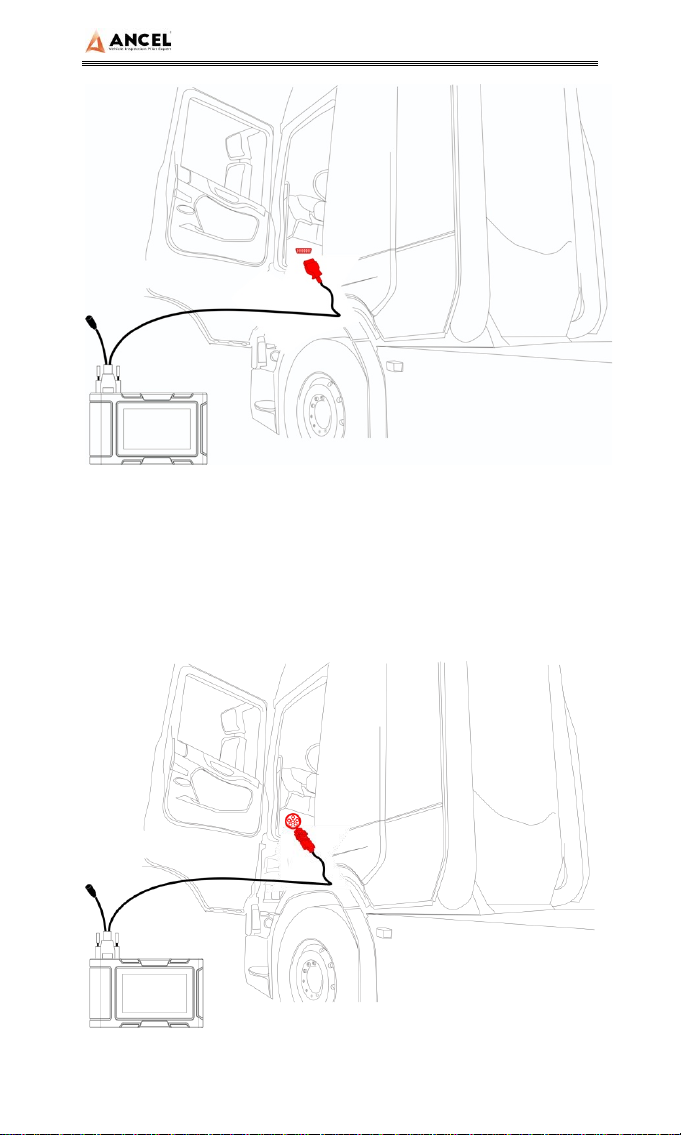
Power on the power adapter: plug one end of the main
diagnostic test line into the DB-15 interface of the device,
connect the power adapter, and the device will start
automatically.
Note: the voltage of the power supply should be within the
scope of application of the product equipment. If it is
beyond the scope, the product may be damaged.
2) Power off
Before power off, please stop all diagnostic items and return
back to the main interface.
Pull out the diagnostic main test line from the diagnostic
interface of the vehicle. If the device is not equipped with
battery, the device will shut down automatically after
disconnecting the main test line from the diagnostic interface of
the vehicle.
Vehicle Diagnostic Preparation
The diagnostic program establishes data connection through
the vehicle electronic control system connected with the
equipment, which can read the vehicle diagnostic information,
view the data flow, and perform action test and other functions.
For details of the functions, please refer to the model which you
purchased.
To establish good communication between the diagnostic
program and the vehicle, the following operations need to be

HD Series
8
performed:
1) Turn off the ignition;
2) Find the diagnostic interface of the vehicle: it is usually
located on the driver side; If the diagnostic interface is not
found, please refer to the vehicle maintenance manual.
3) Insert one end of the diagnostic main test line into the
device DB-15 connector and tighten the retaining screws. The
other end is connected to the vehicle's diagnostic interface.
Note: Before the equipment is connected to the vehicle, it
is necessary to judge whether the diagnostic seat of the
vehicle is a standard OBD-II interface or a non-standard
OBD-II interface.
The vehicle compatible with OBD-II management system
only needs to use the integrated main test line OBD
connector to connect with the vehicle diagnosis seat and
provide power;
For vehicles that are not compatible with the OBD-II
management system, the corresponding connector should
be selected; Some vehicles need to be powered by other
vehicle power sources.
The following is an operation description of these two
connection modes.
1) Connection of standard OBD-II interface
The vehicle connected with standard OBD-II interface only
needs to use the integrated main test line OBD connector, and
no other connectors are needed, as shown in the figure:

HD Series
9
2) Connection of non OBD-II interface
Vehicles with non OBD-II interface need to connect the main
test line with the corresponding special connector, as shown in
the figure:

HD Series
10
Note: at this time, the equipment is powered by the vehicle
diagnosis seat, and the equipment starts automatically. If not, it
may be that the vehicle diagnosis seat has no power supply,
and the equipment can be powered by the cigarette lighter or
battery clip.
Introduction of Each Function Menu
After the system is started, the main menu of function will be
entered. The main menu of each version of model will be
slightly different. Please refer to the display of the model you
purchased.
1) Toolbar (see Table 1)
2) Function main menu (see Table 2)
Table 1: Toolbar
Icon Function
name Function description
Refresh Refresh upgrade menu
Home Return to the main interface of the system
Screenshot Capture current screen picture
Test report
Used to save test data during diagnosis
(can be viewed in data management
menu)

HD Series
11
Icon Function
name Function description
Feedback
Used to report the problem to the
company's service system (need to
connect to the network) when the system
cannot be accessed during the diagnosis
process
Print Used to print test results or test reports.
The printer is optional
Edit Used to edit files, lock, unlock or delete
files
Added Used to add feedback information
WIFI WIFI connection network
Brightness Used to adjust the brightness of the
device screen
Volume Used to adjust the volume of the device
User info Used to view device status and user
information
Data
cleaning
Used to remove useless data from the
device

HD Series
12
General
Used to set device language, unit and
time, view device information and restore
factory settings
Table 2: Function main menu
Icon Function
name Function description
Diesel OBD Diagnostic procedure: Diesel OBD,
see section 5 for details
OBD-II Diagnostic procedure: OBD-II, see
section 5 for details
Service
Reset
Reset the service lamps on the
instrument cluster.
DPF DPF regeneration
Tools
(Pin Detect)For the measurement of
pin voltage of diagnostic interface,
see section 6 for details
Data
management
For browsing and managing saved
data files, see section 7 for details
Update
For online upgrade of system
software and vehicle software, see
section 8 for details
Settings Set and view system information,
see section 9 for details
Diagnostic Function
1) Take【Diesel OBD】as an example;

HD Series
13
Click【DIESEL OBD】menu enter the diagnosis interface.
2) Select connector according to the specific situation, such as
【Diesel6&9PIN】;
3) Select the required diagnostic method, such as 【Standard
protocol(Fast Scan)】;

HD Series
14
4) Click 【Start test】
5) Select【(J1939) Engine】;

HD Series
15
6) Enter【Diagnosis home page】;
The main diagnostic interface usually includes the
following options:
ECU Information: Read and display the control system module
information detected from ECU.

HD Series
16
Read Fault Code: Read the fault code information retrieved
from the vehicle system module.
Erase Fault Code: Clear the fault code and freeze frame data
retrieved from the vehicle system module
Live Data: Read and display the real-time operation
parameters of the current system module

HD Series
17
DPF Regeneration
Select【DPF】in main menu, the screen will display the
vehicle model list and then operate according to the screen
prompt.

HD Series
18
Service Reset
Select 【Service Reset】to reset the service lamps on the
instrument cluster. The service system is designed to alert the
driver when the vehicle is due for a service.
Pin Detect
This function mainly measures the voltage of 16 PIN of OBD
diagnostic interface, and judges the pin position of K- line and
CAN line.

HD Series
19
After connecting the OBD interface of vehicle, click the main
interface 【Tools】to select pin detection. The program
automatically measures the 16pin voltage of OBD diagnosis
interface, and judges the pin position of K-line and can line, as
shown in the figure below:
Data Management
【Data Management】The function is used to save and view
test reports, screenshots and problem feedback files. Most of
the files are generated by executing the toolbar operation of the
vehicle diagnosis interface.

HD Series
20
Diagnostic Software Upgrade
By connecting the device to the wireless network, the diagnostic
software can be upgraded and the product function can be
improved in time. Open 【Update】in the function main menu,
and the system will automatically search for the latest update
program, as shown in the figure below. Click 【Update】to
upgrade the model and other applications to the latest version.
Other manuals for HD Series
1
This manual suits for next models
1
Table of contents
Other ANCEL Diagnostic Equipment manuals