ANCEL X6 User manual


Table of Contents
1 Statement............................................................................................. 1
1.1 Agreement................................................................................... 1
1.2 Copyright information ................................................................. 1
1.3 Disclaimer .................................................................................... 2
1.4 Safety Information....................................................................... 2
1.4.1 Inspection Precautions ..................................................... 3
2 Product description ............................................................................. 6
2.1 Product Overview ........................................................................ 6
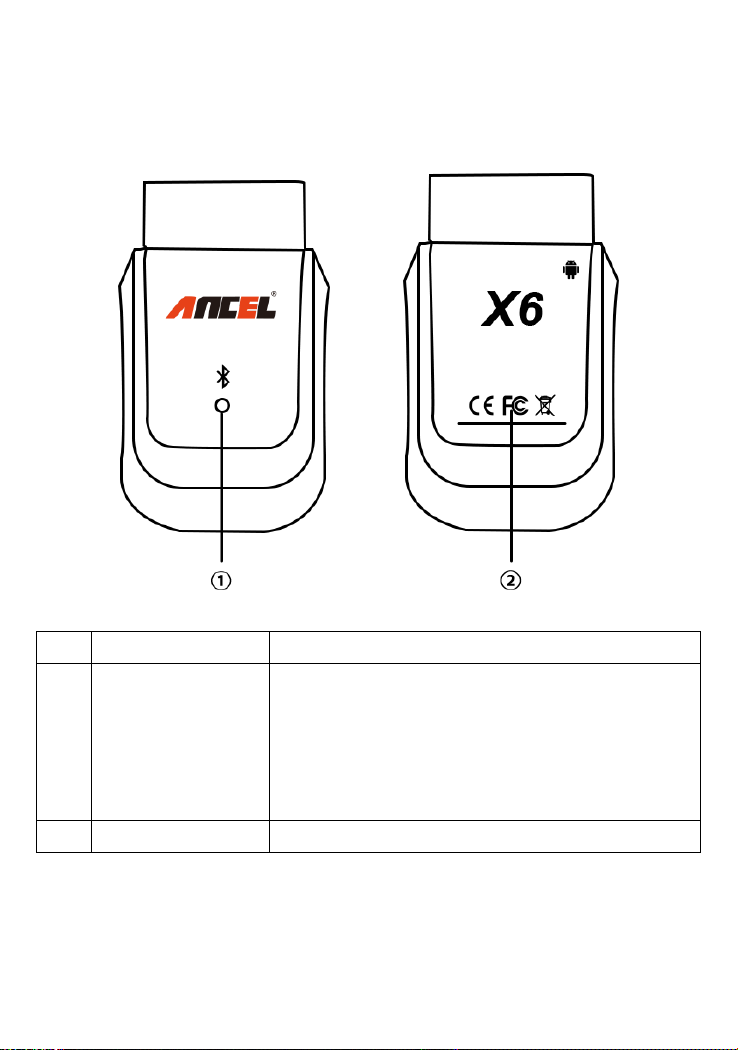
2.2 Ancel X6 VCI box structure description ....................................... 7
2.3 Ancel X7 VCI box structure description ....................................... 9
Product menu introduction.................................................................. 11
3.1 Diagnosis.................................................................................... 12
3.2 Special function ......................................................................... 14
3.3 Update ....................................................................................... 14
3.4 Data Manager............................................................................ 16
3.5 Quick Support............................................................................ 17
3.6 DTC Query.................................................................................. 18
3.7 Feedback.................................................................................... 19
3.8 Data Playback ............................................................................ 20
3.9 Dictionary .................................................................................. 21
3.10 User Manual ............................................................................ 22
3.11 Settings .................................................................................... 23
3.12 User ......................................................................................... 25
4 Vehicle Diagnosis.............................................................................. 26
4.1 First login activation .................................................................. 26

4.2 Data download and product connection................................... 29
4.3 Vehicle diagnosis ....................................................................... 33
5 Software upgrade.............................................................................. 34
6 Cleaning and maintenance and warranty...................................... 36
6.1 Cleaning and maintenance ........................................................ 36
6.2 Warranty.................................................................................... 37

1
1 Statement
You must carefully read the instruction manual, especially the
safety instructions, before you can connect, commission and
operate the products of OBDSPACE TECHNOLOGY CO., LTD.,
Ltd. (hereinafter referred to as “OBDSPACE”).
1.1 Agreement
Once the product is used, it is an endorsement of the following:
(1) Please refer to the packing list of the random distribution for the
configuration equipment of this product, whichever is the actual
product;
(2) The functions and pictures described in this manual are subject
to the actual software. All information, specifications and
illustrations in the manual are the latest information at the time of
publication. The company reserves the right to change it without
notice.
1.2 Copyright information
It cannot be copied or stored in any form(electronic, mechanical,
photocopying, recording or otherwise) without prior written
permission being secured from OBDSPACE. Software and data are
owned by technology and protected by copyright laws, international

2
contract law, and other national laws. It is strictly forbidden to copy
or transfer the data and software or some of the contents. If there is
any violation, the technology will be held legally responsible
according to law.
1.3 Disclaimer
(1) This manual only provides the operation and operation methods
for Ancel X6/X7. The company does not assume any responsibility
for the consequences caused by using the operation methods for
other equipment operations.
(2) The company shall not accept any responsibility for accidents
caused either by the user personally or anyone else, or costs and
expenses due to equipment damages including equipment loss
caused by the user’s abuse or misuse, arbitrary changes or repairs
or operation of the equipment in a manner not in accordance with
the manual requirements.
1.4 Safety Information
For the safety of yourself and others, and to avoid damage to
equipment and vehicles, all personnel handling the equipment must
read the safety precautions mentioned in the manual.

3
1.4.1 Inspection Precautions
(1) Ancel X6/X7 can only be connected to a safety outlet that is
grounded. Before connecting, check and confirm that the diagnostic
circuit is in good condition. Otherwise, it is not necessary to test to
avoid damage to the main unit. If necessary, use a multimeter to
measure the diagnostic seat voltage.
(2) Use only the power cord supplied with the OBDSPACE
diagnostics or detected power line.
(3) Pay special attention to the effects or damage caused by
environmental factors such as acid and alkali, poison gas, and
heavy pressure.
(4) Exhaust gases from the engine contain a variety of toxic
compounds and should be avoided. Park the vehicle in a well
ventilated area before operation.
(5) Do not place the device on the vehicle's power distribution unit.
Strong electromagnetic interference can cause damage to the
equipment.
(6) After the equipment is installed successfully, before starting the
engine, make sure that the parking brake is pulled and the speed
lever is placed in the neutral or parked position to avoid accidents
when the vehicle is started.
(7) When the engine is running at a high temperature, avoid contact

4
with high temperature components such as the water tank and the
exhaust pipe. At the same time, be careful of the voltage generated
by the components such as the ignition coil, the distributor cover,
the ignition circuit and the ignition plug during engine operation.
1.4.2 Notes on the use of the instrument
(1) This instrument is a precision electronic instrument. Do not drop
it. Handle it as gently as possible, away from heat and
electromagnetic fields.
(2) Ensure that the instrument and diagnostics are well connected
so that signal interruptions do not affect the test.
(3) Use screws as much as possible when using the cables and
connectors to avoid disconnecting and damaging the connectors
when moving. Hold the front end of the connector when pulling the
connector, and avoid pulling the rear cable to avoid damage to the
diagnostic interface.
(4) When the electrical components are energized, the circuit
cannot be disconnected to prevent self-inductance, mutual
inductance and current sensors and the vehicle ECU.
(5) The operation of this instrument requires a certain basis for
vehicle inspection and maintenance, and has a certain
understanding of the electronic control system of the vehicle under
test.
1.4.3 Operating car ECU considerations
When performing diagnostic operations on a vehicle equipped with

5
a computer control system, the following should be noted:
(1) Do not place magnetic objects such as radio speakers close to
the computer, as the magnetic properties of the speakers can
damage the circuits and components in the ECU.
(2) When the ignition switch is turned on, the internal electrical
equipment of the car must not be disconnected. Due to the
self-inductance of the coil when disconnected, a high instantaneous
voltage will be generated, which will cause damage to the sensor
and ECU;
(3) When performing repairs near a computer or sensor, special
care should be taken to avoid damage to the ECU and sensor;
(4) When carrying out maintenance work on or near the
ECU-controlled digital meter, be sure to wear a metal strap with one
end clamped to the body and the other end wrapped around the
wrist;
(5) When performing welding work on a car, the ECU system power
should be turned off beforehand;
(6) Do not use test lights to test ECU-related electrical devices to
prevent damage to the ECU or sensor unless specifically stated;
(7) Test ECU and sensors cannot be tested with a pointer-type
ohmmeter, unless otherwise specified in the test procedure, but
should be tested with a high-impedance digital meter.

6
2 Product description
2.1 Product Overview
Ancel X6/X7 Android-based multifunctional diagnostic tool with 8
inch Android tablet developed by OBDSPACE. It has an extensive
vehicle coverage for over 70 car makers from America, Asia,
Europe, Australia and China to meet your basic vehicle diagnostic
needs.

7
2.2 Ancel X6 VCI box structure description
No.
Name
Description
①
Power and
connection
Indicator
Lights on red when powered(connected to
the car)
Lights on blue when the buletoot connected
Lights flashing when the the communication
in process
②
Certification
CE, FCC,RoHS certification

8
VCI Box Parameters
Processor
ARM 32-bit Cortex processor
Input Voltage
DC 8-16V
Operating Temperature
-10 to 70℃(14-158℉),relative
Humidity:<90%
Storage Temperature
-30 to 120℃(-22-248℉),relative
Humidity:<90%
Communication model
Bluetooth
Protocols
ISO 9141, ISO14230, ISO15765,
ISO11898, SAE-J1850 VPW, SAE-1850
PWM, UDS, K/L lines, High speed CAN,
Middle speed CAN, Low speed CAN and
Single wire CAN

9
2.3 Ancel X7 VCI box structure description
2.3-1 VCI Front
No
Name
Description
①
Power Indicator
Lights up when powered(connected
to the car)
②
Vehicle
communication
indicator
Vehicle communication data
③
Bluetooth indicator
Lights up when connected to tablet
④
USB indicator
Lights up when connected to tablet

10
2.3-2 VCI Left
No
Name
Description
⑤
USB interface
Used for wired communication with
tablets
⑥
DC interface
Power supply
2.3-3 VCI Right
No
Name
Description

11
VCI Box Parameters
Processor
ARM 32-bit Cortex processor
Input Voltage
DC 8-16V
Operating Temperature
-10 to 70℃(14-158℉),relative
Humidity:<90%
Storage Temperature
-30 to 120℃(-22-248℉),relative
Humidity:<90%
Communication model
Bluetooth or USB
Protocols
J1708, J1939, ISO 9141, ISO14230,
ISO15765, ISO11898, SAE-J1850 VPW,
SAE-1850 PWM, UDS, K/L lines, High
speed CAN, Middle speed CAN, Low
speed CAN and Single wire CAN
Product menu introduction
Turn on the power switch, turn the host on, and enter the following
interface:
⑦
DB15 interface
Connect to the main testing line,
connect to the vehicle through the
diagnostic connector

12
3.1 Diagnosis
Vehicle diagnosis, different car systems, systems, etc., based on
the actual display menu.

13

14
3.2 Special function
Including ABS BLEEDING, BATTERY, DPF ,EPB, IMMOKEYS, INJECTOR,
OILRESET, SAS, THROTTLE, TPMS, etc.
3.3 Update
After logging in, you can view the model/system data.
• Support WIFI automatic upgrade and one-click upgrade, easy to

15
operate
• Provides version information, software release time, and software
upgrades, so users can quickly learn about updates.

16
3.4 Data Manager
The storage location of vehicle applications, test pictures, videos,
reports and for user reference.

17
3.5 Quick Support
The function allows OBDSPACE technical staff to connect to your
host through the network remotely to help you diagnose the vehicle.
This manual suits for next models
1
Table of contents
Other ANCEL Diagnostic Equipment manuals
Popular Diagnostic Equipment manuals by other brands

Foxwell
Foxwell i70TS manual

Humzor
Humzor NC610 user manual

Mitchell Diagnostics
Mitchell Diagnostics MD-350 quick start guide

Bosch
Bosch FSA 740 Original instructions

Rockwell Automation
Rockwell Automation Allen-Bradley ControlNet NetChecker user manual

Launch
Launch Creader Professional CRP129E user manual

Drucker Diagnostics
Drucker Diagnostics Horizon 6 FA Operator's manual

LAUNCH TECH
LAUNCH TECH X-431 PRO5 user manual

LAUNCH TECH
LAUNCH TECH X-431 Diagun III user manual

Gap Diagnostic
Gap Diagnostic IIDTool BT Ownership and operation guide

Humzor
Humzor NEXZDAS PRO manual

Tech4Life
Tech4Life eSteth Lite manual