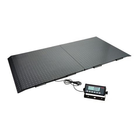
AND FG-CWP Series User manual

FG-CWP Series
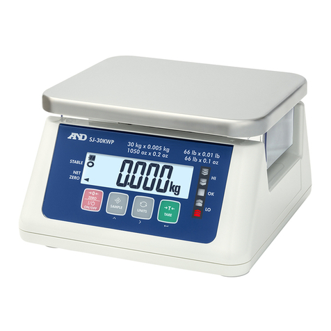
Waterproof Digital Platform Scale
FG-30KCMWP
FG-60KCLWP
FG-150KCLWP
1WMPD4004367

2
This Manual and Marks
All safety messages are identified by the following, “WARNING” or “CAUTION”, of
ANSI Z535.4 (American National Standard Institute: Product Safety Signs and
Labels). The meanings are as follows:
This is a hazard alert mark.
© 2022 A&D Company Ltd. All rights reserved.
No part of this publication may be reproduced, transmitted, transcribed, or translated into any
language in any form by any means without the written permission of A&D Company Ltd.
The contents of this manual and the specifications of the instrument covered by this manual
are subject to change for improvement without notice.
Windows, Word and Excel are registered trademarks of the Microsoft Corporation.
WARNING A potentially hazardous situation which, if not avoided, could
result in death or serious injury.
CAUTION A potentially hazardous situation which, if not avoided, may
result in minor or moderate injury.

3
Contents
1. Compliance ..........................................................................................................................................5
1.1. Compliance with FCC rules ...........................................................................................................5
1.2. Classification of Protection Provided by Enclosures .....................................................................5
2. Introduction..........................................................................................................................................6
3. Outline and Features...........................................................................................................................6
4. Cautions ...............................................................................................................................................7
4.1. Precautions for Installing the Scale ...............................................................................................7
4.2. Precautions for Weighing...............................................................................................................7
4.3. Precautions for Storing ..................................................................................................................7
5. Items Included .....................................................................................................................................8
6. Part Names...........................................................................................................................................8
6.1. Display and Symbols .....................................................................................................................9
6.2. Operation Keys ............................................................................................................................10
7. Setup................................................................................................................................................... 11
7.1. Attaching Pole to Base................................................................................................................. 11
7.2. Installation.................................................................................................................................... 11
8. Basic Operation .................................................................................................................................12
8.1. Turning Power On and Off ...........................................................................................................12
8.1.1. Mobile Battery ......................................................................................................................13
8.2. Basic Operation ...........................................................................................................................13
8.3. Readability ...................................................................................................................................14
9. Counting Function.............................................................................................................................14
10. Comparator Function........................................................................................................................15
10.1. How to Operate............................................................................................................................16
10.2. Selecting the Memory Number ....................................................................................................16
10.3. Confirming the HI/LO Value .........................................................................................................17
10.4. HI/LO value setting ......................................................................................................................18
11.Display Hold Function.......................................................................................................................19
12. Impact Shock Detection Function (ISD) ..........................................................................................19
13. Auto-Tare Function............................................................................................................................20
14. Sensitivity Adjustment......................................................................................................................21
14.1. Sensitivity adjustment Items ........................................................................................................21
14.2. Sensitivity adjustment Using a Weight.........................................................................................23
14.3. Correcting for Gravitational Acceleration .....................................................................................24
14.4. Restoring Sensitivity Adjustment Value to Factory Default..........................................................25
15. Function Table ...................................................................................................................................26
15.1. Parameter Setting Procedure ......................................................................................................26
15.2. func setting .................................................................................................................................26

4
15.2.1. Setting Example ...................................................................................................................27
15.3. id setting ...................................................................................................................................27
15.4. pa55wd setting .............................................................................................................................27
15.5. Restoring Function Tables to Factory Default..............................................................................28
15.6. Parameter List..............................................................................................................................29
16. Communication .................................................................................................................................33
16.1. USB interface...............................................................................................................................33
16.2. Data Format .................................................................................................................................35
17. Options ...............................................................................................................................................41
17.1. Option list .....................................................................................................................................41
18. ID Number and GMP, GLP.................................................................................................................42
18.1. ID Number Setting Procedure......................................................................................................42
18.2. GMP, GLP Report.......................................................................................................................43
19. Password Lock Function..................................................................................................................47
19.1. Setting Procedure ........................................................................................................................47
19.2. To change the function table after setting lock 1 or 2..............................................................48
19.2.1. To change the function table in admin .................................................................................48
19.2.2. To change the function table in gUe5t ................................................................................49
19.2.3. Parameter list that can be changed in gue5t......................................................................49
19.2.4. If you forget the password....................................................................................................50
20. Maintenance.......................................................................................................................................51
20.1. Repair...........................................................................................................................................51
20.2. Check Points Before Calling Maintenance Service .....................................................................51
20.3. Error code table ...........................................................................................................................52
21. Specifications ....................................................................................................................................53
21.1. Specifications list .........................................................................................................................53
21.2. Dimensions ..................................................................................................................................54
Gravity Acceleration Map ........................................................................................................................55

5
1. Compliance
1.1. Compliance with FCC rules
□Please note that this equipment generates, uses and can radiate radio frequency energy. It has
been tested and found to comply with the limits of a Class A computing device pursuant to
Subpart J of Part 15 of FCC rules. These rules are designed to provide reasonable protection
against interference when it is operated in a commercial environment. If it is operated in a
residential area, it might cause some interference and under these circumstances the user
would be required to take, at their own expense, whatever measures are necessary to eliminate
the interference.
(FCC = Federal Communications Commission in the U.S.A.)
1.2. Classification of Protection Provided by Enclosures
□This equipment complies with the IP Code IEC 60529.
The meaning of the IP67 code is as follows:
IP : International Protection.
6 :Protection against ingress of dustandairborne particles.
7 :Protection against water and liquids, up to and included submersion of up to one meter.

6
2. Introduction
Thank you for purchasing this A&D Water proof digital platform scale. This manual describes how
the FG-CWP Series Super Washdown Scales work and how to maximize their performance.
Please read this manual completely before using the scale.
3. Outline and Features
The FG-CWP series has the following features.
□The scale is made of all stainless steel and has waterproof/dustproof performance compliant
with IP67.
(Intrusion of water into the device is prevented even when submerged to a depth of 1 m for
30 minutes.)
□The FG-CWP series has four display resolutions: 1/3,000, 1/6,000 (1/7,500 with some models),
1/12,000 (1/15,000 with some models), and 1/30,000. Resolution can be switched as needed
for the usage. (Resolution = Readability / Weighing capacity)
□The FG-CWP series has two sizes of weighing pans: M size for FG-30KCMWP and L size for
FG-60KCLWP / FG-150KCLWP.
□The scales use a backlit liquid crystal display to enable viewing in dim light.
□The AC adapter or a mobile battery can be used to supply power.
□Weighing data can be transmitted to a PC using a USB cable, the FG-27CWP option (To
communicate using FG-27CWP, AD-8541-PC is required separately).
□9.Counting Function determines the number of objects based on the mass value (total weight)
when each item has the same mass value.
□10.Comparator Function compares the displayed value (measured value) with the previously
set comparator values and indicates the results on the large and bright LED display.
□Up to 10 comparator value settings can be stored in memory.
□11.Display hold function fixes display the weighed value in place to facilitate reading.
□12.Impact shock detection function (ISD) displays the shock level applied to the mass sensor
section.
□13.Auto-tare function, used with comparator mode, automatically tares and displays “OK” for a
certain amount of sample and repeats this process for the next weighing.
□The following parameters are stored in the scale even if the power is turned off.
Unit weight of counting function
HI/LO values of comparator function
Sensitivity adjustment data
Parameters of the function table

7
4. Cautions
4.1. Precautions for Installing the Scale
□Ground the scale, so that the user will not be subjected to an electric shock.
□To prevent electric shock, do not handle the USB cable with wet hands.
□The USB cable is not waterproof. Install the scale in an area where it will not get wet.
□Do not install the scale where flammable or corrosive gas is present.
□Do not put excessive force on cables.
□The scale is heavy. Use caution, as lifting may cause it to fall over.
Consider the following installation conditions to get the greatest performance
from your scale.
□Install the scale in an indoor location out of direct sunlight with stable temperature and
humidity that is free of drafts and vibrations, on a solid and level surface and with a stable
power supply.
□Do not install on a soft floor or where there is vibration.
□Do not install where there is wind or large fluctuations in temperature.
□Avoid locations in direct sunlight.
□Do not install in locations with strong magnetic fields or strong radio signals.
□Do not install where static electricity is likely to occur. When humidity is 45% R.H. or less,
plastic and insulating materials are apt to be charged with static electricity due to friction, etc.
□Unstable AC power supply may cause malfunctions.
□Remove the protective film from the weighing pan before use.
□Sensitivity adjustment should be performed for more accurate weighing when the scale is first
installed or when it is moved far. Refer to “14. Sensitivity adjustment” for details.
4.2. Precautions for Weighing
□Do not place loads on the weighing pan that exceed the weighing capacity.
□Periodic sensitivity adjustment is recommended in order to maintain accurate weighing.
(Refer to “14. Sensitivity Adjustment”)
□Do not apply shock to or drop anything on the weighing pan.
□Do not use a sharp instrument such as a pencil or pen to press keys or switches.
□Press the ZERO key before each weighing to reduce the chance of error.
□Do not weigh when the scale is immersed in water.
□Periodically confirm that weighed values are correct.
□The panel on the rear of the display unit should be kept closed during use to ensure it is
dustproof and water proof.
4.3. Precautions for Storing
□Do not disassemble the scale.
□If the scale becomes dirty, wipe it with a soft cloth slightly moistened with a mild detergent or
a rubbing alcohol (70% or less). Do not use organic solvents.
□Do not scrub with a brush or the like.
□Do not spray with strong jets of water.
DANGER

8
5. Items Included
The following items are packed.
●Main Unit ●Quick Start Guide
FG-30KCMWP FG-60KCLWP
FG-150KCLWP
6. Part Names
●AC Adapter
Weighing Pan
(SUS304)
Display Unit (SUS304)
USB Cable
(
Approx.3m
)
USB Plug
Base Unit
(SUS304)
Load Cell
Cable
Rear of
Display Unit
Leveling Feet
Rating Label
Serial Number
Pole
(SUS304)
Display
unit knob

9
6.1. Display and Symbols
Display Unit
Display/symbol Description
STABLE
〇
This is lit when the weighed value is stable, indicating that the scale is in
the proper condition for reading weighed values.
NET This is lit when weight of the container (tare) is subtracted.
ZERO This is lit when the scale is at the zero point (reference point for weighing).
Weighing Units “kg”, “g” ,“pcs” ,“oz” and “lb” is lit.
Note: “g” is only used with the FG-30KCMW P.
This is lit when the display is held.
This is a function to detect impact to the mass sensor section and to
display the impact level.
Lights up when successfully connected to the optional FG-27CWP
(Bluetooth communication interface).
While the comparator function is being used, the weighed value is
compared using the preset threshold values and the indicator displays the
result.
Weighing
Condition
Conditions for
Each Function
Weighing Units
Comparator LED

10
6.2. Operation Keys
Operation key Description
ON/OFF Key
Shows or hides the display.
Note: When the power plug of the scale is connected, power is supplied
to the electric circuits inside the scale.
SAMPLE Key
Selecting “pcs” as the unit activates individual weight setting mode.
Pressing and holding activates comparator threshold setting mode.
PRINT Key
Outputs the weighed value as data.
Increases the value of the digit flashing when setting.
MODE Key
Switches the weighing unit.
Shifts to the right the digit flashing when making settings.
ZERO Key
Performs zeroing operation. (See below.)
TARE Key
Performs tare operation. (See below.)
Saves the set value and proceeds to the next item when setting.
Zeroing operation
With the zero point gained when turning on the display (power on zero function) as reference,
pressing the ZERO key when the weighed value is stable within ±2% of the weighing
capacity sets the zero point there and the zero point indicator ◄ is lit when zero is displayed.
If tare function is in use, the net is deleted.
Tare function
Pressing the TARE key when the weighed value is a stable positive value subtracts the
weight of the item on the weighing pan as the weight of the container (tare) weight. The
displayed value becomes zero value and both the zero point indicator ◄ and net indicator ◄
are lit.
If the container (tare) is removed from the weighing pan while the tare function is in use and
the value returns to the zero point, net is displayed as a negative value.
Note: The weighing range is reduced by the amount of the tare mass.
Power on Zero Function
Power on zero is a function that displays zero along with the zero point indicator ◄when the
display is turned on by the ON/OFF key with nothing on the weighing pan.
The power on zero function can be used within a range ±50% of weighing capacity from zero
during sensitivity adjustment.
Note: If a tare or similar device is used on the weighing pan before weighing starts (power on),
weighing performance may be affected.

11
7. Setup
7.1. Attaching Pole to Base
1. Take the base unit and the pole out of the
packaging box while being careful not to pull the
load cell cable.
2. Remove the weighing pan from the base.
3. Remove the two screws from the bottom of the
base unit, insert the pole into the base unit, taking
care not to damage the load cell cable, and fix the
pole to the base unit with the two screws you
removed.
Bundle the excess load cell cable from the display
unit side into the pole.
4. Put the weighing pan on the base unit.
7.2. Installation
1. Decide where to install the scale by
considering the descriptions of "4.1.
Precautions for Installing the Scale".
2. Level the base unit by adjusting the four
leveling feet of the base unit so that the
bubble of the spirit level is centered
3. Follow the procedure below to change the
display unit angle.
(1) Turn the two knobs (display unit knobs)
on the rear of the display unit and
remove them.
(2) Tilt the display unit to the desired angle.
(3) Replace and tighten the display unit
knobs removed in step 1.
2.
1.
3.
Weighing
Pan
Pole
Base Unit
Display Unit
Load Cell Cable
NG
OK
Bubble
Spirit Level
Leveling
Foot
Display
Unit Knob

12
If using the scale in a location where static electricity
is easily generated or where it may get wet, secure
the grounding wire with the protective grounding
terminal (screw).
8. Basic Operation
8.1. Turning Power On and Off
1. Insert the USB plug into the AC adapter included with this product and connect it to the
power supply.
□Confirm that local voltage and receptacle type are correct.
□AC adapters other than the one supplied with this product may also be used. It can also
be powered via the USB port or with a mobile battery.
Note: Not all operations are guaranteed.
□The USB cable is used for both power and communication.
2. Pressing the ON/OFF key turns on the display. All indications are lit and the scale waits
for the weighed value to stabilize.
□p------- is displayed when the display is turned on with an object placed on the
weighing pan that exceeds the working range of power-on-zero or when the weighed
value is not stable. Refer to “20.2 Check Points Before Calling Maintenance Service”.
Automatic Power On Function
The scale automatically turns on when power is supplied. See the “15.3 Parameter List” and
set to p-on 1 .
3. Pressing the ON/OFF key while the scale is on turns off the scale.
Automatic Power Off Function
This function turns the display off when the specified interval has passed, the weighed value
is stable and there is no key operation. See the “15.3 Parameter List” and set to poff 1 .
Protective
Grounding
Terminal
Rear of Display Unit

13
8.1.1. Mobile Battery
If using a mobile battery
□Turn off the scale and disconnect the AC adapter if using a mobile battery.
□Connect the USB plug to the mobile battery. Refer to "15. Function Table" to set the function
table bat 2 .
□The continuous usage time is approximately 77 hours at 10000 mAh with the backlight
on. This value is for reference only
□Do not set the bat 1 .
Cautions on using the mobile battery
Check the battery level with your mobile battery.
Not guaranteed to work with all mobile batteries.
Confirm the mobile battery's specifications before use. The warranty does not cover
malfunctions caused by use of a mobile battery.
8.2. Basic Operation
1. Press the ON/OFF key to turn on the scale.
Operation will start with the weighing unit used when the
power was last turned off.
2. Use the MODE key to select the weighing unit to use.
3. If the display is not zero, press the ZERO key to zero
the display.
4. If using a container (tare), place that on the weighing pan
and press the TARE1key to zero the display.
5. Place the object to weigh on the weighing pan or in the
container, wait for the stability indicator to light up, and
then read the displayed value.
6. Remove the object weighed from the weighing pan.
□Weighing can be done from zero to weighing capacity, but
the tare weight is subtracted from the weighing capacity for
the zero point after using the tare function.
□The ZERO key and TARE key work after the weighed
value is stable.
風袋引中
ゼロ点
安定
風袋引中
Container
Weighing Pan
NET
Press
Object
Weighed
NET
ZERO
STABLE
STABLE

14
8.3. Readability
Mass can be displayed on FG-CWP series with the following four types of readability (scale
interval or "division"). The ratio of readability and weighing capacity expressed as display
resolution is shown in the following table.
Function table
Display resolution
re5o 0 (low resolution) 1/3000
re5o 1 (normal resolution) 1/6000 or 1/7500
re5o 2 (high resolution) 1/12000 or 1/15000
re5o 3 (max resolution) 1/30000
Readability is set to normal resolution at time of shipping. It can be changed in the function table
item re5o as needed for the usage environment. See "15. Function Table" for details on how to
configure the settings.
□Calculation to display the count in counting mode is done at max resolution regardless
of the set display resolution.
9. Counting Function
This function stores the mass (unit weight) of a single item from a known number of sample masses,
and calculates and displays the number of items based on that value and the total mass.
□The unit mass is stored in non-volatile memory
even when power is turned off.
1. Press the MODE key to display the weighing
unit “pcs”.
(pcs = pieces)
2. Display the unit mass stored by pressing the
SAMPLE key. The figure on the left is the
sample count.
3. Press the PRINT key to change the sample
count. Select from 5, l0, 20, 50 and l00 pcs.
4. When “-“ appears at the right side of the number
of samples, press the ZERO key to zero the
scale. If necessary, place a container on the
weighing pan, and press the TARE key.
Confirm that the right side of the number of
samples shows zero.
5. Place the number of samples shown on the
weighing pan or into the container.
Press
(select)
ZERO
STABLE
ZERO
STABLE
Number of samples
STABLE
Container
Weighing
Pan
ZERO
NET
STABLE
Sample
Press
Press
(select)
Press
Confirm
zero
STABLE
Weighing

15
6. Confirm that the stability indicator is lit, and then press
the SAMPLE key to calculate and store the unit
mass. The display changes to the count using the unit
mass stored. Remove the sample.
□The mass of the number of samples must be at least
the values below, regardless of the sample count.
Weighing capacity
Minimum
mass
FG-30KCMWP
10g
FG-60KCLWP
20g
FG-150KCLWP
50g
If the sample mass is small, lo ut is displayed and returns to the display in step 5. Increase
the number of samples (see step 3) and try again.
□If you press the SAMPLE key without reaching the minimum mass in the table above,
you will be returned to weighing mode.
10.Comparator Function
The comparator function compares the weighed value against the set values and displays the results
using LEDs (yellow / green / red). Comparison is done based on the following table, and the
results are displayed/output.
Judgment
result
Judgment formula
HI HI limit value < Displayed value (Or when positive value)
OK LO limit value ≦Displayed value ≦HI limit value
LO Displayed value < LO limit value (Or when negative value)
□Select the comparison condition in function table item Cp . (Refer to "15. Function Table")
Function
table
Content
Cp 0 No comparison (comparator function unavailable).
Cp 1 All weighed values are compared regardless of stability.
Cp 2 All stable weighed values are compared.
Cp 3
Weighed values except those at -4d to +4d are compared regardless of
stability
Cp 4 All stable weighed values except those at -4d to +4d are compared.
Cp 5 Weighed values +5d and above are compared regardless of stability.
Cp 6 Stable weighed values at +5d and above are compared.
d= readability (scale interval or "division") (see the “basic manual” included with the product)
Even in the counting function, “d” is the readability in the mass display.
□The HI/LO values are stored in non-volatile memory even when power is turned off.
□The HI/LO values are the same in both mass display and count display.
□The decimal point is ignored for HI/LO values.
When parameter is “0010000” with the FG-30KCMWP (decimal point ignored)
Yellow
Green
Red
LED Display
LO
OK
HI
STABLE
STABLE
Press

16
Display Parameter
Weighing capacity / Readability
display
Low resolution
10.000 kg
30.00 kg / 0.01 kg
Normal resolution
10.000 kg
30.000 kg / 0.005 kg
High resolution
10.000 kg
30.000 kg / 0.002 kg
Max resolution
10.000 kg
30.000 kg / 0.001 kg
Counting mode
10000 pcs
10.1. How to Operate
1. Press and hold the SAMPLE key while in
mass display to enter comparator setting
mode.
2. Display the selected memory number (0-9).
3. Each time the PRINT key is pressed, the
memory number display will be switched. The
currently selected memory number is
indicated by the “○” mark being lit.
10.2. Selecting the Memory Number
1. Press and hold the SAMPLE key while in
mass display to enter comparator setting
mode and push the PRINT key to change
the memory number display.
2. Press the TARE key to change the
memory number. After displaying end , the
device returns to weighing mode.
3. Start comparing using the memory number
changed to.
STABLE
ZERO
Press and Hold
Press
Press
STABLE
ZERO

17
10.3. Checking the HI/LO Value
1. Press and hold the SAMPLE key while in
mass display to enter comparator setting mode
and push the PRINT key to change the
memory number display.
2. Press the MODE key. LO is lit and the lower
limit value of the memory number selected is
displayed.
3. Press the MODE key. HI is lit and the upper
limit value of the memory number selected is
displayed.
4. To return to the memory number display, press
the MODE key.
5. To return to weighing mode, press the TARE
key.(Start comparing using the memory number
displayed at this time.)
Press
Press
Press
STABLE
ZERO
Press
HI
OK
LO
HI
OK
LO

18
10.4. Setting HI/LO value
1. Press and hold the SAMPLE key while in mass
display to enter comparator setting mode and push
the PRINT key to change the memory number
display.
2. Press the MODE key. LO is lit and the lower limit
value is displayed.
3. Press the TARE key. The digit of the value blinks.
Change the value with the keys below.
□Example of changing setting
4. Press the TARE key to display end , HI is lit
and the upper limit value blinks.
5. Change the upper limit value in the same way you
adjusted the lower limit.
6. Press the TARE key to display end and
return to the memory number display.
7. Press the TARE key to return to weighing
mode after end is displayed. (Start comparing
using the memory number displayed at this time.)
key
Content
Moves the blinking digit.
Increases the blinking digit by 1.
Sets (stores) the parameter.
Press
HI
OK
LO
Press
HI
OK
LO
HI
OK
LO
Press
HI
OK
LO
HI
OK
LO
Press
STABLE
ZERO
Press

19
11. Display Hold Function
This function holds and displays the weighed value when the it is in the set condition.
HOLD lights up while the display is held.
Display Hold Condition
The weighed value is held and displayed when it becomes stable at 5d or more, or when the
weighing value is 5d or more and fluctuates within the "Display hold width" for 2 seconds.
Cancel display hold condition
When the weighed value fluctuates from the value being held on the display by 10 times the
"Display hold width" or becomes smaller than 5d, the display hold state is canceled when the
"Hold release time" elapses.
□The "d" represents the minimum display.
□The "Display hold width” can be selected by the item Hold in "15.3. Parameter List”
□The “Hold release time” can be selected by the item Hd-t in "15.3. Parameter List”
12. Impact Shock Detection Function (ISD)
The FG-CWP series has a function to detect impact to the mass sensor section and to display
the impact level. By lowering the impact level at the time of loading, it is possible not only to
alleviate variation in the weighed value but also to reduce the risk of failure of the mass sensor
section.
Impact level display is from level 0 to level 3, 4 level.
Impact level Shock indicator Contents
0 No Safe
1
Caution:Consider impact mitigation.
2
Warning:Do not apply greater impact.
3
Danger:Sensor may be damaged.
Refer to "15. Function Table" and set the internal setting to i5d 1 to turn on the function of
displaying the shock level.
□There is no buzzer sound or memory function upon detection.
Note
□Impact on the weighing sensor may be applied to the weighing pan at time of loading, or it may
be applied from the floor on which the scale is installed. The impact detection function also
works for impact applied from the floor.

20
13. Auto-Tare Function
The FG-CWP has an auto-tare function, used together with the comparator function, that
enables masses within a certain range (OK) to be weighed in succession as the scale
automatically tares. First place a container on the weighing pan. Press the TARE key to
zero the display once the container is weighed. Gradually place or take away objects until
the comparison result shows OK. When the result shows OK and the measurement stable
time set for the function table item
at-t has elapsed, the scale will automatically tare the weighed value and return to zero,
indicating it is ready for the next weighing. Repeat this process to compare weights.
□In order to use the auto-tare function, function tables must be configured as follows.
(Refer to "15. Function Table")
Function
table
Content
Cp 1 Compare regardless of stability of weighed value (other settings may be
used depending on the application).
at 1 Enable auto-tare function.
at-t 0~9
Condition for taring automatically (Select according to the content and
method of work in order to eliminate incorrect operations, such as instantly
judging to be OK and starting taring even though actual mass is not OK,
and to eliminate excessively long wait times.)
□Tak e-away check weighing Cp-p 1
This is a method of comparing against negative mass values. After a container with
objects in it is placed on the weighing pan and tared, take objects away while staying in
the OK range to compare masses.
The same operation is also possible in the ordinary method of comparing, but comparison
results start from HI, changing from HI to OK to LO as more objects are taken away. With
this setting, comparison results are shown in the order LO to OK to HI (negative
comparison) as objects are taken away in order to make this easier to understand
intuitively. Set to Cp-p 1 along with at 1 for the auto-tare function.
In this setting, both positive and negative values can be set for LO and HI values, ignoring
polarity. The comparison results are as shown in the table below.
□When function table at-f 1 (automatically tare initial load) is set.
To start the auto-tare function, a container filled with objects needs to be placed on the
weighing pan and its weighied value tared using the TARE key. By setting at-f 1 ,
the mass of the container placed on the scale after confirming zero is automatically tared.
After weighing then removing everything placed on the weighing pan, the scale returns to
the zero point and the tare weight is automatically cleared. If the scale does not return to
the zero point, the tare weight can be cleared by setting it to zero with the ZERO key.
+Mass
-Mass
LO
limit value
HI
limit value
Net 0
This manual suits for next models
3
Other AND Scale manuals
AND
AND UC-352BLE User manual
AND
AND HV-CWP Series User manual
AND
AND HV-15KC User manual
AND
AND LifeSource UC-350CNBLE User manual
AND
AND HR Series User manual
AND
AND UC-355PBT-Ci User manual
AND
AND PLUSCONNECT UC-350CNBLE User manual
AND
AND EK-120G User manual
AND
AND GR Series User manual
AND
AND PLUS CONNECT UC-350BLE User manual
