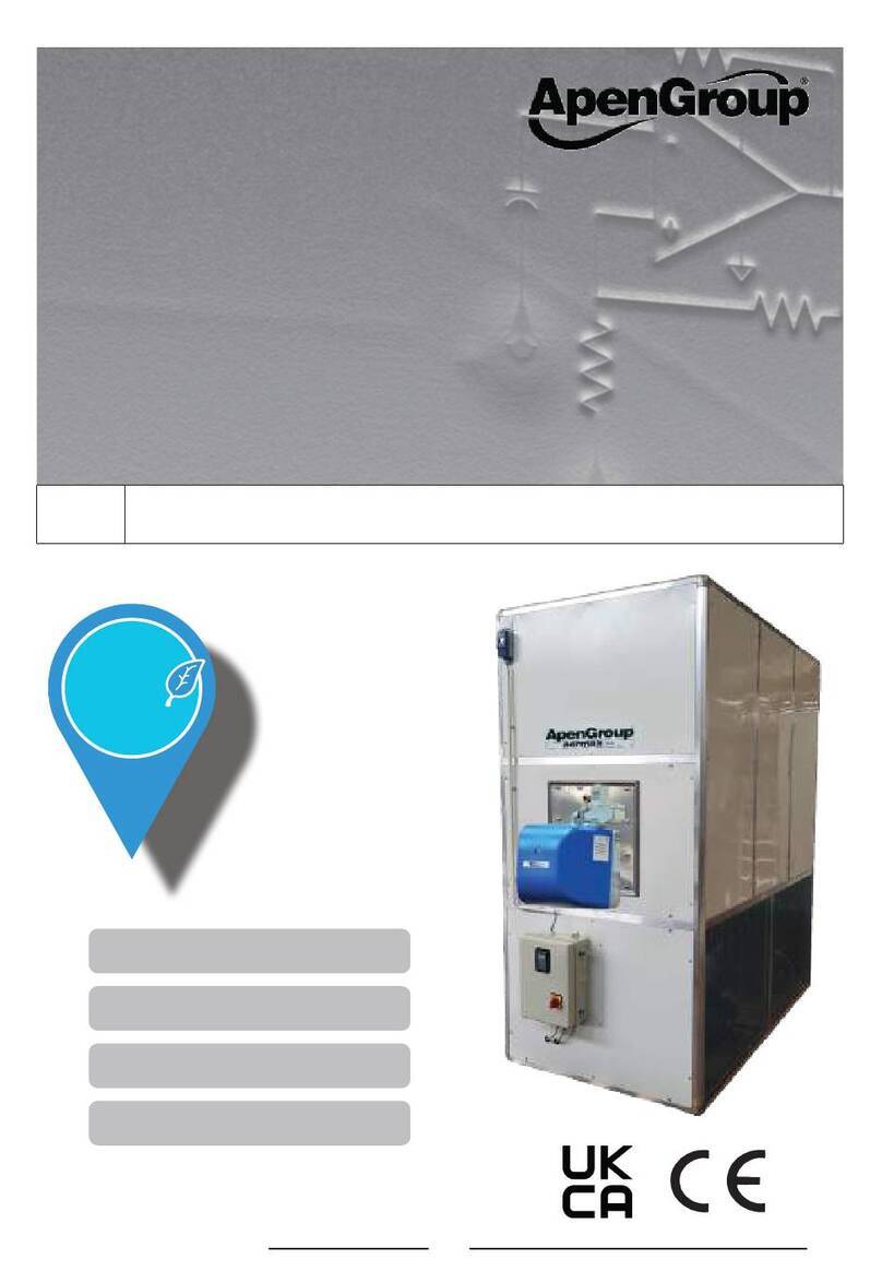
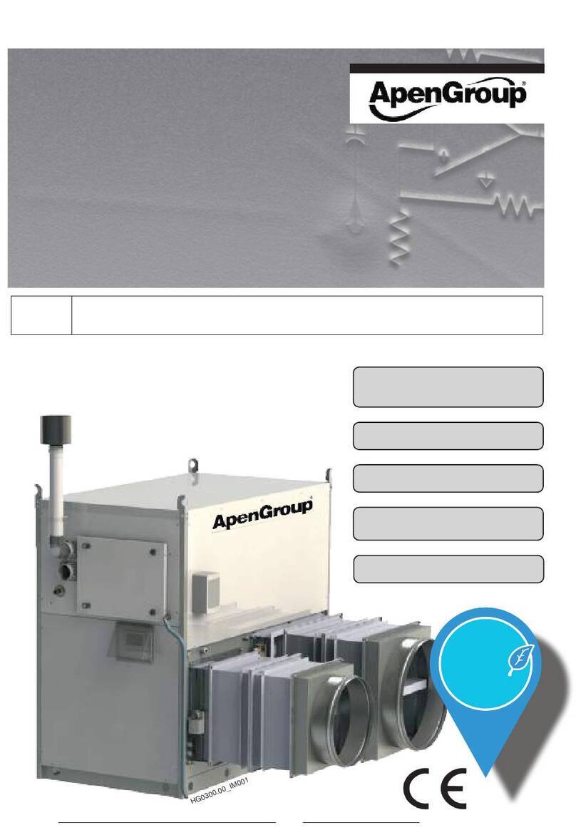
ApenGroup PKE-SPORT Series Installation and user guide

1code HG0335.00GB ed.B-2310
PK-SPORT APEN GROUP SPA reserves the right to make changes deemed to be required to its products or documentation
ErP
2021
Compliant
EU/2016/2281
Capacities from 100 to 550 kW
Eciency up to 102.4%
Reduction of
Thermal Stratication
NEW VERSION
CPU G26800
GB Maintenance, installation and service manual
PKE-SPORT series oor standing warm air heater with NEW CPU

PK-SPORT
code HG0335.00GB ed.B-2310 2
APEN GROUP SPAreserves the right to make changes deemed to be required to its products or documentation
Floor Standing Warm Air Heater PK SPORT
Use, Installation and Maintenance Manual
VER. 01.2020
CODE SERIAL NUMBER
Dichiarazione di Conformità
Statement of Compliance
APEN GROUP S.p.A.
20042 Pessano con Bornago (MI)
Via Isonzo, 1
Tel +39.02.9596931 r.a.
Fax +39.02.95742758
Internet: http://www.apengroup.com
Il presente documento dichiara che la macchina:
With this document we declare that the unit:
Modello:
Model:
Generatore a basamento PK PKA-N, PKA-K, PKA-R, PKE-N, PKE-K, PKE-R
Floor Standing Heater PK PKA-N, PKA-K, PKA-R, PKE-N, PKE-K, PKE-R
è stata progettata e costruita in conformità con le disposizioni delle Direttive Comunitarie:
has been designed and manufactured in compliance with the prescriptions of the following EC Directives:
•Regolamento Apparecchi a Gas 2016/426/UE
Gas Appliance Regulation 2016/426/UE
•Direttiva Bassa Tensione 2014/35/UE
Low Voltage Directive 2014/35/UE
•Direttiva Compatibilità elettromagnetica 2014/30/UE
Electromagnetic Compatibility Directive 2014/30/UE
•Regolamento ErP 2016/2281/UE
ErP Regulation 2016/2281/UE
•Direttiva ROHS II 2011/65/UE e ROHS III 2015/863/UE
ROHS II 2011/65/UE and ROHS III 2015/863/UE Directives
Valido solo per gli accoppiamenti generatore-bruciatore indicati dal costruttore (vedere manuale)
Valid only for the heater-burner matching specified by the manufacturer (see manual)
è stata progettata e costruita in conformità con le norme:
has been designed and manufactured in compliance with the standards:
•EN17082:2020
•2017/C 229/01
•EN60335-1
•EN60335-2-102
Organismo Notificato:
Notified body:
Kiwa Cermet Italia S.p.A
0476
PIN 0476CT2224
La presente dichiarazione di conformità è rilasciata sotto la responsabilità esclusiva del fabbricante
This declaration of conformity is issued under the sole responsibility of the manufacturer
Pessano con Bornago
29/03/2022 Apen Group S.p.A.
Un Amministratore
Mariagiovanna Rigamonti

3code HG0335.00GB ed.B-2310
PK-SPORT APEN GROUP SPA reserves the right to make changes deemed to be required to its products or documentation
Floor Standing Warm Air Heater PK SPORT
Use, Installation and Maintenance Manual
sZϬϱϮϬϮϯ
K ^Z/>EhDZ
h<ĞĐůĂƌĂƚŝŽŶŽĨŽŶĨŽƌŵŝƚLJ
WE'ZKhW^Ɖ
ϮϬϬϰϮWĞƐƐĂŶŽĐŽŶŽƌŶĂŐŽ;D/Ϳ
sŝĂ/ƐŽŶnjŽϭͲ/d>z
dĞůнϯϵϬϮϵϱϵϲϵϯϭƌĂ
&ĂdžнϯϵϬϮϵϱϳϰϮϳϱϴ
/ŶƚĞƌŶĞƚŚƚƚƉǁǁǁĂƉĞŶŐƌŽƵƉĐŽŵ
tŝƚŚƚŚŝƐĚŽĐƵŵĞŶƚǁĞĚĞĐůĂƌĞƚŚĂƚƚŚĞƵŶŝƚ
DŽĚĞů
&ůŽŽƌ^ƚĂŶĚŝŶŐ,ĞĂƚĞƌW<W<ͲEW<Ͳ<W<ͲZW<ͲEW<Ͳ<W<ͲZ
ŚĂƐďĞĞŶĚĞƐŝŐŶĞĚĂŶĚŵĂŶƵĨĂĐƚƵƌĞĚŝŶĐŽŵƉůŝĂŶĐĞǁŝƚŚƚŚĞƉƌĞƐĐƌŝƉƚŝŽŶƐŽĨƚŚĞĨŽůůŽǁŝŶŐZĞŐƵůĂƚŝŽŶƐ
•ZĞŐƵůĂƚŝŽŶϮϬϭϲϰϮϲŽŶŐĂƐĂƉƉůŝĂŶĐĞƐĂƐďƌŽƵŐŚƚŝŶƚŽh<ůĂǁĂŶĚĂŵĞŶĚĞĚ
•ůĞĐƚƌŽŵĂŐŶĞƚŝĐŽŵƉĂƚŝďŝůŝƚLJZĞŐƵůĂƚŝŽŶƐϮϬϭϲ
•ůĞĐƚƌŝĐĂůƋƵŝƉŵĞŶƚ;^ĂĨĞƚLJͿZĞŐƵůĂƚŝŽŶƐϮϬϭϲ
•dŚĞZĞƐƚƌŝĐƚŝŽŶŽĨƚŚĞhƐĞŽĨĞƌƚĂŝŶ,ĂnjĂƌĚŽƵƐ^ƵďƐƚĂŶĐĞƐŝŶůĞĐƚƌŝĐĂůĂŶĚůĞĐƚƌŽŶŝĐƋƵŝƉŵĞŶƚ
ZĞŐƵůĂƚŝŽŶƐϮϬϭϮ
•ƌWZĞŐƵůĂƚŝŽŶϮϬϭϲϮϮϴϭh
ŚĂƐďĞĞŶĚĞƐŝŐŶĞĚĂŶĚŵĂŶƵĨĂĐƚƵƌĞĚŝŶĐŽŵƉůŝĂŶĐĞǁŝƚŚƚŚĞƐƚĂŶĚĂƌĚƐ
•EϭϳϬϴϮϮϬϮϬ
•ϮϬϭϳϮϮϵϬϭ
•EϲϬϯϯϱͲϭ
•EϲϬϯϯϱͲϮͲϭϬϮ
EŽƚŝĨŝĞĚďŽĚLJ
<ŝǁĂh<
Ϭϱϱϴ
W/EϬϰϳϲdϮϮϮϰ
dŚŝƐĚĞĐůĂƌĂƚŝŽŶŽĨĐŽŶĨŽƌŵŝƚLJŝƐŝƐƐƵĞĚƵŶĚĞƌƚŚĞƐŽůĞƌĞƐƉŽŶƐŝďŝůŝƚLJŽĨƚŚĞŵĂŶƵĨĂĐƚƵƌĞƌ
WĞƐƐĂŶŽĐŽŶŽƌŶĂŐŽ ƉĞŶ'ƌŽƵƉ^Ɖ
ϭϬϬϱϮϬϮϯ hŶŵŵŝŶŝƐƚƌĂƚŽƌĞ
DĂƌŝĂŐŝŽǀĂŶŶĂZŝŐĂŵŽŶƚŝ

PK-SPORT
code HG0335.00GB ed.B-2310 4
APEN GROUP SPAreserves the right to make changes deemed to be required to its products or documentation
Floor Standing Warm Air Heater PK SPORT
Use, Installation and Maintenance Manual
TABLE OF CONTENTS
1. GENERAL CAUTIONS ................................................................................................................................................................6
2. SAFETY-RELATED WARNINGS ...............................................................................................................................................6
2.1. Fuel ...........................................................................................................................................................................................................6
2.2. Gas Leaks.................................................................................................................................................................................................7
2.3. Power supply ............................................................................................................................................................................................7
2.4. Use............................................................................................................................................................................................................7
2.5. Air Vents....................................................................................................................................................................................................7
2.6. Maintenance.............................................................................................................................................................................................7
2.7. Transport and Handling............................................................................................................................................................................8
2.8. Packaging.................................................................................................................................................................................................8
2.9. Unpacking.................................................................................................................................................................................................8
2.10. Dismantling and demolition......................................................................................................................................................................9
2.11. How to Identify the Heater......................................................................................................................................................................10
3. TECHNICAL FEATURES ..........................................................................................................................................................11
3.1. Main Components...................................................................................................................................................................................11
3.2. Choosing the Heater...............................................................................................................................................................................12
3.2.1. Diagramsofoutputheat/eciencyratioofPK-Nheaters ...........................................................................................................12
3.2.2. Diagramsofoutputheat/eciencyratioofPK-Kheaters............................................................................................................13
3.2.3. Diagramsofoutputheat/eciencyratioofPK-Rheaters ...........................................................................................................14
3.3. Technical Data........................................................................................................................................................................................15
3.3.1. HeatinputandeciencydataofPKE-Nheaters ........................................................................................................................15
3.3.2. HeatinputandeciencydataofPKE-Kcondensingheaters.....................................................................................................16
3.3.3. HeatinputandeciencydataofPKE-Rcondensingheaters.....................................................................................................17
3.3.4. Airowratetechnicaldata,headpressureandinstalledpowersupply......................................................................................18
3.4. Noise.......................................................................................................................................................................................................19
3.5. DimensionsofPKSPORTHeater..........................................................................................................................................................20
4. USER'S INSTRUCTIONS .........................................................................................................................................................22
4.1. Operation ................................................................................................................................................................................................22
4.2. RemoteOn/O(optional) .......................................................................................................................................................................23
4.3. Ventilation operating logic......................................................................................................................................................................23
4.4. Temperature Adjustment Accessories...................................................................................................................................................24
4.4.1. SmartXWeb ................................................................................................................................................................................24
4.5. Pressure Control ....................................................................................................................................................................................25
4.5.1. Manualoperation(“MAN”) ...........................................................................................................................................................25
4.5.2. Control setpoints ..........................................................................................................................................................................26
4.5.3. Automaticoperation(“AUTO”) .....................................................................................................................................................26
4.6. WindControl ..........................................................................................................................................................................................27
4.7. SnowControl .........................................................................................................................................................................................29
4.7.1. Manualoperation(“MAN”) ...........................................................................................................................................................29
4.7.2. Automaticoperation(“AUTO”)(ONLYIFexternalsensorandprobeAREPRESENT)............................................................. 30
4.8. AN3inputconguration..........................................................................................................................................................................31
4.9. WEBconguration..................................................................................................................................................................................31
4.10.OptionalAccessoriesRequired..............................................................................................................................................................32
4.10.1. TENSOSTATICbuildings .............................................................................................................................................................32
4.10.2. PRESSOSTATICbuildings...........................................................................................................................................................33
4.11. Optionalaccessories ..............................................................................................................................................................................34
4. INSTRUCTIONS TO THE INSTALLER ...................................................................................................................................41
4.1. WheretoInstalltheHeater.....................................................................................................................................................................41
4.2. WiringtoPowerSupply ..........................................................................................................................................................................42
4.2.1. Cables...........................................................................................................................................................................................42
4.3. Electrical connections.............................................................................................................................................................................43
4.4. WiringtheBurner................................................................................................................................................................................... 44

5code HG0335.00GB ed.B-2310
PK-SPORT APEN GROUP SPA reserves the right to make changes deemed to be required to its products or documentation
Floor Standing Warm Air Heater PK SPORT
Use, Installation and Maintenance Manual
5. SERVICING INSTRUCTIONS .................................................................................................................................................. 45
5.1. OperatingCycle......................................................................................................................................................................................45
5.2. Interface Panel .......................................................................................................................................................................................45
5.3. Reset.......................................................................................................................................................................................................46
5.4. SmartXWebconnection........................................................................................................................................................................46
5.5. ModulationPCBParameters..................................................................................................................................................................47
5.6. Analysisoflockouts-faults .....................................................................................................................................................................53
5.7. ElectricalWiringandDiagrams..............................................................................................................................................................54
5.8. BurnerMatching .....................................................................................................................................................................................57
5.9. Gasburners ............................................................................................................................................................................................58
5.10.Burnermatchingtables...........................................................................................................................................................................58
6. MAINTENANCE ......................................................................................................................................................................... 59
6.1. ControlsatFirstStartUp........................................................................................................................................................................59
6.2. RoutineMaintenance..............................................................................................................................................................................60
6.3. List of spare parts...................................................................................................................................................................................61

PK-SPORT
code HG0335.00GB ed.B-2310 6
APEN GROUP SPA reserves the right to make changes deemed to be required to its products or documentation
Floor Standing Warm Air Heater PK SPORT
Use, Installation and Maintenance Manual
1. GENERAL CAUTIONS
This manual is an integral part of the product and must always
accompany it.
Should the equipment be sold or passed on to someone else,
alwaysmakesurethatthismanualissuppliedwiththeequipment
for future consultation by the new owner and/or installer.
themanufacturershallnotbeheldcivillyorcriminallyresponsible
for injuries to people or animals or damages to things caused by
incorrectinstallation,calibrationandmaintenanceorbyfailureto
follow the instructions contained in this manual or by operations
carried out by unqualied sta.
This product must be used only for the applications for which it
was designed. Any other use must be regarded as hazardous.
During the installation, operation and maintenance of the
equipmentdescribedinthismanual,theusermustalwaysstrictly
follow the instructions given in all the chapters of this use and
instruction manual.
The warm air heater must be installed in compliance with
current regulations, according to the manufacturer's
instructions and by qualied sta, technically specialised
in the heating eld.
“First ignition, conversion from one family gas
to another and maintenance must be
carried out only by suitably qualied sta of Technical Service
Centres
complyingwiththerequisites required bytheregulationsinforce
in their country.
Maintenance must be carried out with methods
and timing that comply with current and previous regulations
in force in the country where the equipment is to be installed.
ForItaly,the “technicalservice”tabofApenGroupwebsitewww.
apengroup.com indicates several Technical Service Centres
that the user can contact to have the rst start-up, adjustment
and maintenance of the product carried out according to law
37/2007 (ex 46/90)
For more information, visit our website www.apengroup.com or
contact Apen Group directly.
The warranty conditions are specied on the warranty certicate
supplied with this equipment."
2. SAFETY-RELATED WARNINGS
The following symbol is used in this manual whenever it is
necessary to draw the operator’s attention on a safety issue.
Accident prevention regulations concerning
the operator and sta operating in the vicinity.
Please nd below the safety regulations for the installation room
and the air vents.
2.1. Fuel
The heater must be matched to a suitable burner, using the fuel
chosen for the equipment.
The burner shall use the type of fuel it is set for, which is specied
on the equipment plate and in technical specications in burner’s
Manual.
In case of a gas burner, the pressure of the gas supplying the
burner and the combustion head must be within the range of
values indicated in the manual.
On K and R series condensing heaters, only gas burners
can be used.
Before starting the burner/heater, check that:
• the gas mains supply data are compatible with the data
stated on the nameplate;
• the combustion air is supplied in such a way as to avoid
even partial obstructions of the intake grille;
• the gas seal of the feeding system has been tested and
approved in compliance with the applicable standards;
• the heater burner is supplied with the same type of fuel it
has been designed for;
• the system is correctly sized to match required ow rate,
indicated in the manual, and includes all safety and control
devices required by the law;
• gaspipes andair distributionducts for ducted heaters have
been thoroughly cleaned;
• the fuel ow rate is suitable for the power required by the
heater;
• the fuel supply pressure is between the range specied on
the nameplate.
When connecting gas supply pipe to gas valve, do not
tighten excessively in order to avoid damaging sealing
gaskets.

7code HG0335.00GB ed.B-2310
PK-SPORT APEN GROUP SPA reserves the right to make changes deemed to be required to its products or documentation
Floor Standing Warm Air Heater PK SPORT
Use, Installation and Maintenance Manual
2.2. Gas Leaks
If you smell gas:
• donotoperateelectricalswitches,thetelephoneoranyother
object or device that can cause sparks or naked ames;
• immediately open doors and windows to create an air ow
to vent the gas out of the room;
• close the gas valves;
• switch o the power supply via a disconnector outside the unit;
• call for qualied sta;
• call the Fire Brigade.
2.3. Power supply
The heater must be correctly connected to an eective earthing
system, tted in compliance with current legislation.
Cautions:
• Check the eciency of the earthing system and, if required,
call out a qualied engineer.
• Checkthatthemainspowersupplyisthesameasthepower
inputstatedontheequipmentnameplateandinthismanual.
• Donotreverseliveandneutral;theheatercanbeconnected
to the mains power supply with a plug-socket only if the latter
does not allow live and neutral to be swapped.
• The electrical system and, more specically, the cable
section,mustbesuitablefortheequipmentmaximumpower
input, shown on the nameplate and in this manual.
• Do not pull electric cables and keep them away from heat
sources.
NOTE: It is compulsory to install, upstream of the power cable,
a switch with a protection (fuses or automatic), as required by
existing regulations. The switch must be visible, accessible
andplacedatadistancelowerthan3metresfromthecontrol
compartment; any electrical operation (installation and
maintenance) must be performed by qualied sta.
2.4. Use
Do not allow children or inexperienced people to use any
electrically powered equipment.
The following instructions must be adhered to:
• do not touch the equipment with wet or damp parts of your
body and/or with bare feet;
• do not leave the equipment exposed to the elements (rain,
sun etc...) unless it is adequately protected;
• do not use the gas pipes to earth electrical equipment;
• do not wet the heater with water or other uids;
• do not place any object over the equipment;
• do not touch the moving parts of the heater.
• Avoid contact with hot heater surfaces.
Such surfaces, generally located near the ame, overheat
during operation and remain hot for some time after the burner
has stopped.
If the equipment is not to be used for a certain period of time,
open the main electrical switch of the thermal station and close
the manual valve on the duct which brings the fuel to the burner.
If, instead, the equipment is not to be used any more, perform
the following operations:
• a qualied person shall disconnect the power supply cable
from the main switch;
• close the manual valve on the duct supplying fuel to the
burner by removing or locking the control handwheel.
2.5. Air Vents
The room where gas red heater will be installed must be provided
with one or more air vents. These air vents must be tted
• ush to the ceiling for gases with density lower than 0.8sqm;
• ush to the oor for gases with density higher than or equal
to 0.8sqm.
The air vents must be tted to walls facing the open air. The
sections must be sized according to the heat output installed.
In case of doubt, measure the CO2with the burner working at
maximum output rate and the room ventilated only through the
air vents for the burner and then measure again with the door
closed. C02value must be the same under both conditions. If
in the same room there are several burners or aspirators that
can work together, measure with all the equipment working at
the same time.
Donotobstructtheroomairvents,theburnerfanintakeopening,
any air ductwork and intake or dissipation grilles, avoiding in
this way:
• stagnationintheroomofanytoxicand/orexplosivemixture;
• smouldering combustion: dangerous, expensive, pollutant.
The heater, if not built for outdoor installation, shall be sheltered
from rain, snow, and frost. If air is pulled from outdoor, the intake
must be protected by a rain deector or similar device that prevents
water from penetrating into the heater.
The room where the heater-burner group is installed must be
clean and deprived of volatile substances that can be drawn by
the fan and obstruct burner inner hoses or combustion head.
Dust itself can be a problem if it is left depositing on fan blades,
thus reducing fan ow rate and making combustion polluting.
Moreover dust can deposit on the back of ame stability disk in
combustion head, degrading air-fuel mixing ratio.
2.6. Maintenance
Before carrying out any cleaning and maintenance operations,
isolate the unit from the mains power supply using the switch
located on the electrical system and/or on the shut-o devices.
If the equipment is faulty and/or incorrectly operating, switch it
o and do not attempt to repair it yourself, but contact our local
Technical Service Centre.
Use only original spare parts for repairs. Failure to follow above
instructions could compromise the unit safety and shall void the
warranty.
PK-SPORT
code HG0335.00GB ed.B-2310 8
APEN GROUP SPA reserves the right to make changes deemed to be required to its products or documentation
Floor Standing Warm Air Heater PK SPORT
Use, Installation and Maintenance Manual
2.7. Transport and Handling
Vertical heaters are delivered fastened to a pallet. Horizontal
heaters have their own base.
Unload the heater from the truck and move it to the site of
installation by using means of transport suitable for the shape
and for the weight of the load.
Anyliftingandtransportoperationsmustbecarriedoutbyskilled
sta, adequately trained and informed on the working procedures
and safety regulations. Instructions in this Manual shall have to
be followed when handling the exchanger.
Basedontheir weightanddimensions, heaterscanbe liftedwith
lift trucks or wheel-mounted crane.
In the rst case, use fork extensions as long as heater width.
HG0150 C3 001
2.8. Packaging
The unpacking operation must be carried out by using suitable
tools or safety devices where required. Recovered packaging
materials must be separated and disposed of according to
applicable regulations in the country of use.
While unpacking the unit, check that the unit and all its parts
have not been damaged during transport and match the order.
If damages have occurred or parts are found to be missing,
immediately contact the supplier.
The manufacturer is not liable for any damages occurred
during transport, handling and unloading.
2.9. Unpacking
The unpacking operation must be carried out by using suitable
tools or safety devices where required. Recovered packaging
materials must be separated and disposed of according to
applicable regulations in the country of use.
While unpacking the unit, check that the unit and all its parts
have not been damaged during transport and match the order.
If damages have occurred or parts are found to be missing,
immediately contact the supplier.
The manufacturer is not liable for any damages occurred
during transport, handling and unloading.
Packing material disposal
Thepackingsafeguardstheproductfromtransportdamages.All
the materials used are environmentally friendly and recyclable.
Pleasecontactaspecialiseddistributororyourlocaladministration
for more information on waste disposal.

9code HG0335.00GB ed.B-2310
PK-SPORT APEN GROUP SPA reserves the right to make changes deemed to be required to its products or documentation
Floor Standing Warm Air Heater PK SPORT
Use, Installation and Maintenance Manual
2.10. Dismantling and demolition
Should the machine be dismantled or demolished, the person in
charge with the operation shall proceed as follows:
Disposal of end-of-life products
This equipment is marked in compliance with
European Directive 2012/19/EU on waste electrical
and electronic equipment (WEEE). This Directive
denes the rules for collecting and recycling waste
equipments throughout the entire territory of the
European Union.
WEEE contains both pollutants (that can negatively
aect the environment) and raw materials (that can be reused). IT
isthereforenecessarytosubjectWEEEtoappropriatetreatments,
inordertoremove and safelydisposeofpollutantsand toextract
and recycle raw materials. IT is forbidden to dispose of WEEE
as unsorted waste. These operations facilitate recovery and
recyclingofthematerials,thusreducingtheenvironmentalimpact.
NOTE: All materials recovered will be processed and
disposed of according to what provided for by the laws
in force in the country of use and/or according to the
standards indicated in the safety sheets of the chemicals.
INFORMATION FOR DISPOSAL valid in ITALY (Legislative
Decree 49/2014)
The PK series air handling units and relating accessories
are considered “professional WEEE - waste electrical and
electronicequipment”.AccordingtothelegislationinforceinItaly,
professional WEEE must be sent to treatment plants suitable
for these types of waste. Please contact the Apen Group for
end-of-life products so as to obtain all the information necessary
for their correct waste disposal, which is possible thanks to the
Collective System (Union) to which the company is associated.
Please remember that product disposal without complying with
the mode described above is a violation liable to administrative
and penal sanctions.
INFORMATION FOR DISPOSAL valid abroad (EU COUNTRIES
except Italy).
TheEuropeanDirective2012/19/ECshallbeimplementedinevery
EU member state. There may be dierent application modalities
for the various member states, even in terms of modality for
waste disposal depending on its type (House-hold or Professional
WEEE). To this regard at the end of the life of the product, we
highly recommend you call the distributor or installer so as to
obtain information on the correct disposal, in compliance with
the existing laws of the installation country.

PK-SPORT
code HG0335.00GB ed.B-2310 10
APEN GROUP SPA reserves the right to make changes deemed to be required to its products or documentation
Floor Standing Warm Air Heater PK SPORT
Use, Installation and Maintenance Manual
PK A 250 R -P
Heater
Version:
A (indoor);
E (outdoor).
Capacity
Series:
Standard non-condensing N series
Condensing K series
Condensing R series
Installation:
P - Pressostatic
T - Tensostatic
2.11. How to Identify the Heater
PK warm air heaters can be identied using their nameplate,
stuck on the front of the unit.
The nameplate shows all the data needed for identifying the
heater model.
When contacting your local Service Centre, please note the
heater model and serial number indicated on the plate and use
them to identify the machine you purchased.
Heater Code
HG0150 C3 002

11 code HG0335.00GB ed.B-2310
PK-SPORT APEN GROUP SPA reserves the right to make changes deemed to be required to its products or documentation
Floor Standing Warm Air Heater PK SPORT
Use, Installation and Maintenance Manual
3. TECHNICAL FEATURES
3.1. Main Components
Warmairheatershavebeendesignedforheatingsportfacilities,
respectively PK-T for tensostatic sport structures and PK-P for
pressostatic sport structures.
Warm air heaters include:
• stainless steel heat exchanger
• frame and body
• centrifugal fan and electrical motor
• control panel and settings
• safety devices and controls
In the case of pressostatic structures, in the event of power
failure, the PK-P air heater cannot ensure proper support
of the air dome
The pressure control inside the air dome in PK-P heaters for
pressostatic structures is not a safety feature.
In the event of power failure or malfunctions of the heater, the
latter cannot ensure correct maintenance of pressure inside
the air dome and thus the support of the pressostatic structure.
In accordance with the Standards and Regulations in force at
the place of installation, the PK-P heater must be backed up by
an additional system, operated by a source of energy other than
electricity,suitablysizedaccordingtothestructurebeingserved,
in the event of a main power failure
Stainless steel heat exchanger
The innovative design and large surface of the combustion
chamber and heat exchanger pipes ensure optimum eciency
and durability.
Combustion chamber and ue gas collectors are completely
made of AISI 441 stainless steel with low carbon content, as
well as the surfaces in contact with ue gases (tube bundle) in
order to ensure a high resistance to corrosion.
Tube bundle design is patented.
Characteristics of steel types used
The following table shows naming correspondence of the steel
types used to manufacture our exchangers:
USA -AISI EN - No. Composition
AISI 441 1.4509 X2 CrTiNb 18
Heater’sheatexchangercanworkalsounderconditionsthatlead
tocondensation(ifequippedwiththenecessaryaccessories)only
if the relevant burner is supplied with gaseous fuel.
Frame and body
Theframe consistsofsolid anodisedaluminium bars.Theframe
is assembled with demountable parts allowing, in special cases
such as door crossing, to disassemble and reassemble the
heater completely.
Body panels are formed by:
- on the exchanger side: double-layered panels with inner
galvanized steel sheet, high-density glass bre insulation, external
painted galvanized steel sheet, all riveted to allow an easy and
safe removal of the panel during maintenance.
- on the fan side: painted galvanized steel sheet with inner layer
forthermalandsoundisolation,securelyfastenedtosteelpanel.
Allpanelsfeaturea gasketforaperfectsealing against airleaks.
Centrifugal Fan
Standard centrifugal fans installed (AT and ADH models) are
made of galvanised steel sheet with forward curved blades and
low noise of operation.
Fans are xed on hermetic ball bearings which are self-aligned
and assembled inside rubber dampers.
Fans for square duct are used: driven by means of xed diameter
pulleys and belts, three-phase motor.
No lubrication is required on standard fans. For special fans,
check specic requirements.
Operating Temperatures:
- belt drive -20°C +45°C
The following fans are available on demand:
• backward curved blades
• fans for temperatures lower than -20°C
Electrical Motor
All motors used have the following features:
• Supply 400Vac - Three-phase - 50 Hz
• Structure B3 - with terminal board above
• Protection rating IP55
• Isolation level cl.F
• Eciency IE3
For more model-related information on motors, see further in
this Manual.
If required, motors with the following characteristics can be
supplied:
• various supply voltages, electrical features and physical
shapes;
• motors for low temperatures (below -30°C)
• motors with class H isolation
• tropicalised motors
• motors with internal heat protection, thermostat, or PT100
or PTC probe.
Control Panel and Settings
Standard control panel includes:
• oven-varnished metal box
• quadripolar switch-disconnector, padlockable, with door lock
• protection from overheat and short circuit for each motor
• fuse-protected wiring board to control heater, safety devices
and burner.
• inverter onboard the machine.
Thestandardpanelallowsroomtemperaturesetting.Thesetting
dependsontheburnerinstalled.Thefollowingtypesareavailable:
• two stages, high/low ame
• modulating.
Safety Devices and Controls
All heaters are supplied with:
• STB manual reset safety thermostat, inside the air ow, which
switches o the burner immediately if the temperature is high.
• Delivery NTC NTC probes in the delivery duct, modulate
and/orstoptheburneroperationbeforethesafetythermostat
activates.
• Ambient NTC Ambient NTC probe (to be installed indoor),
modulates and/or stops the burner operation before the
safety thermostat activates.
• SMART X WEB Chronothermostatwithsystemsetting
functions.

PK-SPORT
code HG0335.00GB ed.B-2310 12
APEN GROUP SPA reserves the right to make changes deemed to be required to its products or documentation
Floor Standing Warm Air Heater PK SPORT
Use, Installation and Maintenance Manual
3.2. Choosing the Heater
Heaters are available in condensing versions (K and R series respectively) and in non-condensing version (N series). R series meets
the eciency requests of the regional resolutions of Lombardy, Emilia Romagna and Piedmont; at European level, a matching with
low NOx burners is required in order to comply with the imposed regulatory limitations.
Heaters for indoor installation (PKA) are supplied with heat exchanger, fan unit and control panel to be installed indoor or in a
sheltered position; those for outdoor installation (PKE) are supplied with heat exchanger, fan unit, control panel and burner casing
to be positioned outdoor.
A work eld has been tested and approved for each heater. This eld allows the heater to be used at dierent power and eciency
levels based on eective output power. When choosing a heater model, the following criteria have to be taken into account: its
use, service type (season or all year long), matching burner type (two stages or modulating).
3.2.1. Diagrams of output heat/eciency ratio of PK-N heaters
140
190
250
87
88
89
90
91
92
93
94
95
96
50 100 150 200 250 300 350 400 450 500 550 600 650 700 750 800
Rendimento %
Potenza Termica kW
Potenze - Rendimenti
550
320
420
Eciency %
Heat output kW
KG0100 EG 0011_B
Power - Eciency

13 code HG0335.00GB ed.B-2310
PK-SPORT APEN GROUP SPA reserves the right to make changes deemed to be required to its products or documentation
Floor Standing Warm Air Heater PK SPORT
Use, Installation and Maintenance Manual
3.2.2. Diagrams of output heat/eciency ratio of PK-K heaters
90
92
94
96
98
100
102
104
50 100 150 200 250 300 350 400 450 500 550 600 650 700
Rendimento %
Potenza Termica kW
Potenze - Rendimenti
550
320
420
90
92
94
96
98
100
102
104
0 20 40 60 80 100 120 140 160 180 200 220 240 260
Rendimento %
Potenza Termica kW
Potenze - Rendimenti
100
140
190
250
Heat output kW
Heat output kW
KG0100 EG 006_B
KG0100 EG 008_B
Power - Eciency
Power - Eciency
Eciency %
Eciency %

PK-SPORT
code HG0335.00GB ed.B-2310 14
APEN GROUP SPA reserves the right to make changes deemed to be required to its products or documentation
Floor Standing Warm Air Heater PK SPORT
Use, Installation and Maintenance Manual
3.2.3. Diagrams of output heat/eciency ratio of PK-R heaters
93
94
95
96
97
98
99
100
101
102
103
0 20 40 60 80 100 120 140 160 180 200 220
Rendimento %
Potenza Termica kW
Potenze - Rendimenti
100
140 190
250
Heat output kW
Eciency %
Power - Eciency
KG0100 EG 009_B
Heat output kW
Power - Eciency
KG0100 EG 010_B
94
95
96
97
98
99
100
101
102
50 100 150 200 250 300 350 400 450 500 550
Rendimento %
Potenza Termica kW
Potenze - Rendimenti
550
320
420
Eciency %

15 code HG0335.00GB ed.B-2310
PK-SPORT APEN GROUP SPA reserves the right to make changes deemed to be required to its products or documentation
Floor Standing Warm Air Heater PK SPORT
Use, Installation and Maintenance Manual
3.3. Technical Data
3.3.1. Heat input and eciency data of PKE-N heaters
All PK vertical heaters, up to 320N included, are supplied as a single unit with assembled burner casing.
Model PKE140N PKE190N PKE250N
Type of appliance B23
EC approval 0476CT2224
NOx Class NOxCLASS 5 *
MIN >91% MAX MIN >91% MAX MIN >91% MAX
Furnace Heat Input Pmin;
Pated,h kW 96.0 131.4 195.0 115 202.5 230.0 154.0 252.0 310.0
Useful Heat Output kW 90.2 120.3 171.0 108.1 184.7 205.9 145.0 230.2 275.0
Combustion Eciency ηpl;
ηnom
%94.0 91.4 87.7 94.0 91.2 89.5 94.0 91.3 88.7
Seasonal energy eciency
of heating system ηs,h %According to the chosen burner: see table in Par. 5.10
Output eciency ηs,ow %According to the chosen burner: see table in Par. 6.9
Chimney loss - Burner ON % 6.0 8.6 12.3 6.0 8.8 10.5 6.0 8.7 12.3
Chimney loss - Burner OFF % < 0.1 <0,1 <0,1
Casing losses Fenv %1.26 1.16 1.17
Combustion Chamber pressure Pa 13 28 50 10 32 40 10 36 50
Combustion Chamber volume m30.37 0.52 0.76
Model PKE320N PKE420N PKE550N
Type of appliance B23
EC approval 0476CT2224
NOx Class NOxCLASS 5 *
MIN >91% MAX MIN >91% MAX MIN >91% MAX
Furnace Heat Input Pmin;
Pated,h kW 185.0 309.0 380.0 260 398 508 320 515 670
Useful Heat Output kW 173.9 282.1 335.9 245 364 450 301 471 592
Combustion Eciency ηpl;
ηnom
%94.0 91.3 87.7 94.4 91.5 88.6 94.3 91.5 88.4
Seasonal energy eciency
of heating system ηs,h %According to the chosen burner: see table in Par. 5.10
Output eciency ηs,ow %According to the chosen burner: see table in Par. 5.10
Chimney loss - Burner ON % 6.0 8.7 12.3 5.6 8.5 11.4 5.7 8.5 11.6
Chimney loss - Burner OFF % < 0.1 < 0.1 < 0.1
Casing losses Fenv %1.02 1.03 0.97
Combustion Chamber pressure Pa 15 45 60 28 85 120 21 80 110
Combustion Chamber volume m31.06 1.55 1.79
*With CLASS 3 GAS BURNERS according to EN676

PK-SPORT
code HG0335.00GB ed.B-2310 16
APEN GROUP SPA reserves the right to make changes deemed to be required to its products or documentation
Floor Standing Warm Air Heater PK SPORT
Use, Installation and Maintenance Manual
3.3.2. Heat input and eciency data of PKE-K condensing heaters
Model PKE100K PKE140K PKE190K PKE250K
Type of appliance B23
EC approval 0476CT2224
NOx Class NOxCLASSE 5*
MIN MAX MIN MAX MIN MAX MIN MAX
Furnace Heat Input Pmin;
Pated,h kW 26.5 114.0 38.0 152.0 48.0 200.0 61.0 270
Useful Heat Output kW 27.1 105.4 38.5 40.8 48.3 185.2 61.6 248.9
Combustion Eciency ηpl;
ηnom
%102.4 92.5 101.2 92.6 100.5 92.6 101.1 92.2
Seasonal energy eciency
of heating system ηs,h %According to the chosen burner: see table in Par. 5.10
Output eciency ηs,ow %According to the chosen burner: see table in Par. 5.10
Chimney loss - Burner ON* % - 8.6 - 8.6 - 8.8 - 8.7
Chimney loss - Burner OFF % < 0.1 < 0.1 <0,1 <0,1
Casing losses Fenv % 1.81 1.26 1.16 1.17
Combustion Chamber pressure Pa 14 100 13 140 10 130 10 175
Combustion Chamber volume m30.37 0.37 0.52 0.76
Model PKE320K PKE420K PKE550K
Type of appliance B23
EC approval 0476CT2224
NOx Class NOxCLASSE 5*
MIN MAX MIN MAX MIN MAX
Furnace Heat Input Pmin;
Pated,h kW 74.0 347.0 83.0 455.0 95.0 595.0
Useful Heat Output kW 74.8 319.8 83.8 419.4 96.1 549.1
Combustion Eciency ηpl;
ηnom
%101.0 92.2 101.0 92.2 101.2 92.2
Seasonal energy eciency
of heating system ηs,h %According to the chosen burner: see table in Par. 5.10
Output eciency ηs,ow %According to the chosen burner: see table in Par. 5.10
Chimney loss - Burner ON* % - 8.7 - 8.5 - 8.5
Chimney loss - Burner OFF % < 0.1 < 0.1 < 0.1
Casing losses Fenv %1.02 1.03 0.97
Combustion Chamber pressure Pa 15 225 28 275 21 365
Combustion Chamber volume m31.06 1.55 1.79
* With CLASS 3 GAS BURNERS according to EN676

17 code HG0335.00GB ed.B-2310
PK-SPORT APEN GROUP SPA reserves the right to make changes deemed to be required to its products or documentation
Floor Standing Warm Air Heater PK SPORT
Use, Installation and Maintenance Manual
* With CLASS 3 GAS BURNERS according to EN676
3.3.3. Heat input and eciency data of PKE-R condensing heaters
Model PKE100R PKE140R PKE190R PKE250R
Type of appliance B23
EC approval 0476CT2224
NOx Class NOxCLASS 5 *
MIN MAX MIN MAX MIN MAX MIN MAX
Furnace Heat Input Pmin;
Pated,h kW 26.5 90.0 38.0 115.9 48.0 162.0 61.0 217.0
Useful Heat Output kW 27.1 84.8 38.5 109.2 48.3 150.6 61.6 205.5
Combustion Eciency ηpl;
ηnom
%102.4 94.1 101.2 94.2 100.5 94.5 101.0 94.7
Seasonal energy eciency
of heating system ηs,h According to the chosen burner: see table in Par. 5.10
Output eciency ηs,ow According to the chosen burner: see table in Par. 5.10
Chimney loss - Burner ON* %-7.5 -7.4 -7.4 - 7.8
Chimney loss - Burner OFF % < 0.1 < 0.1 <0,1 < 0.1
Casing losses Fenv % 1.81 1.26 1.16 1.17
Combustion Chamber pressure Pa 14 100 15 140 15 130 19 175
Combustion Chamber volume m30.24 0.37 0.52 0.76
Model PKE320R PKE420R PKE550R
Type of appliance B23
EC approval 0476CT2224
NOx Class NOxCLASS 5 *
MIN MAX MIN MAX MIN MAX
Furnace Heat Input Pmin;
Pated,h kW 74.0 275.0 83.0 345.0 95.0 450.0
Useful Heat Output kW 74.8 256.5 83.8 325.8 96.1 430.1
Combustion Eciency ηpl;
ηnom
%101.0 94.9 101.0 95.2 101.2 95.3
Seasonal energy eciency
of heating system ηs,h According to the chosen burner: see table in Par. 5.10
Output eciency ηs,ow According to the chosen burner: see table in Par. 5.10
Chimney loss - Burner ON* % - 7.6 - 7.8 - 7.7
Chimney loss - Burner OFF % < 0.1 < 0.1 < 0.1
Casing losses Fenv %1.03 1.03 0.97
Combustion Chamber pressure Pa 23 225 30 275 40 365
Combustion Chamber volume m31.06 1.55 1.79

PK-SPORT
code HG0335.00GB ed.B-2310 18
APEN GROUP SPA reserves the right to make changes deemed to be required to its products or documentation
Floor Standing Warm Air Heater PK SPORT
Use, Installation and Maintenance Manual
3.3.4. Air ow rate technical data, head pressure and installed power supply
Model PKE100 PKE140 PKE190 PKE250 PKE320 PKE420 PKE550
Version P00 P00 P00 P00 P00 P00 P00
Air Flow Rate - 15°C m3/h 7,000 9,800 13,400 18,200 21,800 30,000 35,000
Available head* Pa 300 300 300 300 300 300 300
Heat drop Min and Max ** K10.9 - 46.7 11.1 - 44.5 10.3 - 42.8 9.6 - 42.5 9.7 - 45.6 7.9 - 43.5 7.8 - 48.7
Power supply V 400T
Frequency Hz 50
Motor Max. capacity*** kW 3.0 4.0 4.0 7.5 7.5 11 15
Max. Absorbed power**** kW 3.51 4.61 4.61 8.45 8.45 12.19 16.48
Protection Rating IP PKE heater = IP24; PKE control panel = IP55
Operating Temperature °C from -20°C to + 40°C (check running temperature of matching burner)
* Chimney losses at minimum power for PK-K and PK-R heaters are zero because the eciency, calculated on LVC (Low Caloric
Value of natural gas) exceeds 100%.
** Minimum heat drop is referred to minimum heat input, while maximum heat drop refers to maximum heat input
*** Max. capacity refers to the maximum power delivered by the motor; as for the heater, the power actually delivered by the motor
depends on the fan working position with respect to the air distribution system’s drops (system drops)
**** Maximum absorbed power refers to the maximum power delivered by the motor considering the supplied motor eciency
(eciency IE3); the power absorbed by the matching burner must be add to the value indicated in the table.

19 code HG0335.00GB ed.B-2310
PK-SPORT APEN GROUP SPA reserves the right to make changes deemed to be required to its products or documentation
Floor Standing Warm Air Heater PK SPORT
Use, Installation and Maintenance Manual
3.4. Noise
DUCTED HEATERS
The following table shows sound power values, LwA, and sound
pressure values, LpA, issued by PK-SPORT heaters. The value
refers to heaters with ducted intake and delivery and when the
heater is installed outdoor.
Fortheseapplications thevaluesof fansoundpower, intakeand
deliveryare added up,the resulting value is properlyreduced by
the sound insulation value ensured by sandwich panels.
The values in the table refer to power, LwA, which passes through
the heater sandwich panels.
For the values of fan noise in ducts for air intake and delivery,
contact the Technical Support.
Special attention must be paid to the noise conditions
required for the room, dimensioning and installing, where
necessary, silencers in the ductwork
HG0150 C3 003
Heater with ducted delivery and intake
MODEL LwA - Sound Power Level [dB(A)] LwA distance LpA
63 125 250 500 1000 2000 4000 8000 dB(A) metres dB(A)
PKE100 57.3 63.4 66.1 67.4 71.5 71.4 69.0 61.2 76.9 6 56.4
PKE140 55.1 61.5 65.5 70.2 72.4 72.9 71.0 63.4 78.3 657.8
PKE190 59.6 61.1 66.4 68.2 72.2 72.4 70.3 60.9 77.7 6 57.2
PKE250 62.3 64.9 69.9 73.6 78.6 78.0 76.9 68.9 83.6 6 63.1
PKE320 69.5 67.4 68.2 71.3 72.3 71.7 67.9 60.0 78.7 658.1
PKE420 75.7 72.3 70.2 74.8 74.0 72.6 68.4 60.8 81.6 6 61.1
PKE550 74.3 70.2 71.8 72.7 75.1 72.5 67.8 59.0 81.1 6 60.5

PK-SPORT
code HG0335.00GB ed.B-2310 20
APEN GROUP SPA reserves the right to make changes deemed to be required to its products or documentation
Floor Standing Warm Air Heater PK SPORT
Use, Installation and Maintenance Manual
3.5. Dimensions of PK SPORT Heater
Integrated Models
All PK vertical heaters, up to 320 included, are supplied as a
single unit with assembled burner casing.
Three-Assembly Models
From 420 model onward, heaters consist of three assemblies:
fan, exchanger, and burner casing. The rst two assemblies,
fan and exchanger, are to be installed one on top of the other
without any xing. Fan assembly includes slots for sliding the
two parts into place.
To install burner casing onto the heater, do the following:
• lay transparent silicone on the edges of burner casing
• lift the burner casing, resting it against the heater and
matching aluminium bars.
• x the support, on the casing, to the heater bars using the
supplied screws.
Then ll any gaps in joint areas with silicone, in order to protect
all internal parts (control panel, burner,etc.) from water.
Usethesuppliedpolarisedconnectorfortheelectricalconnection
between exchanger (thermostats) and control panel.
Air intake and delivery
Standard ambient air intake and air delivery are on the right side
of the heater (seen from the burner). External air intake and
smoke protection shutter (if any) are always positioned on the
opposite side with respect to air delivery.
Upon request, it is possible to order the heater with ambient air
intake and air delivery on the left side.
HG0150 C2 001
Model Overall dimensions Intake Delivery Chimney Burner Weight
L B HLG LV E G HB BA HA BM HM N ØR S ØT kg
PKE100 1,955 800 2,120 1,455 500 875 290 540 500 800 500 800 1,760 180 1,190 190 445
PKE140 2,170 920 2,180 1,570 600 990 290 540 500 800 500 800 1,800 180 1,155 190 525
PKE190 2,480 1,060 2,330 1,750 730 1,070 340 540 600 800 600 800 1,960 250 1,190 190 650
PKE250 2,760 1,140 2,430 1,960 800 1,180 390 540 700 800 700 800 2,020 250 1,180 190 845
PKE320 3,110 1,140 2,610 2,310 800 1,430 440 540 800 800 800 800 2,040 250 1,180 230 990
PKE420 3,310 1,340 3,100 2,460 850 1,205 500 700 900 1,100 900 1,100 2,780 300 1,740 230 1,200
PKE550 3,600 1,340 3,270 2,600 1,000 1,600 500 745 900 1,190 900 1,190 2,900 300 1,830 230 1,450
This manual suits for next models
27
Table of contents
Other ApenGroup Heater manuals

ApenGroup
ApenGroup AermaxLine LRP-RAPID PRO Series Technical manual

ApenGroup
ApenGroup Aermax PCH Manual

ApenGroup
ApenGroup PK Series Technical manual

ApenGroup
ApenGroup Aermax line Operating instructions

ApenGroup
ApenGroup AH-Sport User manual

ApenGroup
ApenGroup Aermax AX EC Technical manual

ApenGroup
ApenGroup Aermax Series Technical manual

ApenGroup
ApenGroup AX-EC Series User manual

ApenGroup
ApenGroup QUEEN Series Operating instructions

ApenGroup
ApenGroup aermax line Q Series Technical manual