STEP
LL-66S LEVER LATCH
INSTALLATION INSTRUCTION
Thank you for purchasing our product.
Be sure to read and install this product correctly. Keep this manual handy for future reference.
ABOUT THIS PRODUCT
This is for an overlay door to prevent door from opening by the shock of earthquake, but heavy
items may fall inside the cabinet and cause the door to be forced open. Refrain from storing heavy
items inside cabinet.
Recommended door dimension: 700 mm (27”) H x 500 mm (20”)
Applicable cabinet: The under edge of door having 34 mm or more space under the bottom board
of the cabinet.
DRAWINGS
STEP-1 On the back side of the cabinet door, draw a horizontal LINE-A representing the
bottom of the cabinet.
Measure 60 mm (minimum) from the side edge of the door, and then draw a vertical LINE-B.
With the door closed, draw the same LINE-A and LINE-B onto the bottom board of the cabinet.
Based on these lines, nd two points and bore holes of 2-3 mm depth using a gimlet, at the position
shown in the drawing.
※Include distance for spacers or any other objects placed between the door and the cabinet.
Bottom of
cabinet
Back side of door
The Dimension of
Latch Installation
The Dimension of
Strike Plate Installation
※
(minimum)60
10
23 1
LINE-B
LINE-B
Outline of body
56
Latch body
Strike Plate
Bottom of cabinet
Back side of door
Parallel
2
Parallel
※
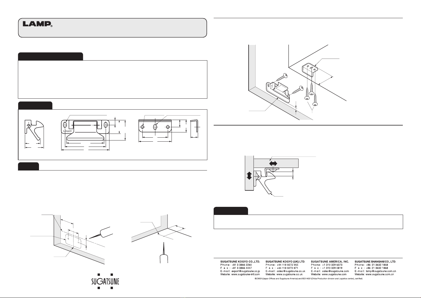
STEP-2 Mount the body of the unit to the back of the cabinet door and mount the strike plate
to the bottom of the cabinet, but do not tighten the screws down at this time.
Ensure that the latch body is parallel with the bottom edge of door and the strike plate parallel with
the front edge of cabinet as shown in the drawing.
REMARKS
The latch may become unable to operate normally during long usage due to warping or sagging of
doors. In such a case, adjust the construction of doors or the position of installation of this product.
STEP-3 Check how the latch works by opening and closing the door.
With the door closed, move the latch body to adjust until it is parallel with the bottom board of the
cabinet. Then tighten all the screws.
To operate: Pull the lever and open the door.
(5.2)
Door
To be adjusted according to
the position of the strike plate.
Latching margin
(to be adjusted according to
the position of the lever.)
Lever
Bottom
Board
In the case that the door joints were
adjusted at the hinges, adjust the
latch accordingly.
10
9.8
6.5
SUS316 PAT
(21) (51.6)
56
66
35
45
(28)
17
Latch body Strike Plate
※Supplied with 5 screws.
2×4.2×7.2 Oblong Hole 2×φ4.2Hole 4.2×7.2 Oblong Hole
(26)
18.5


