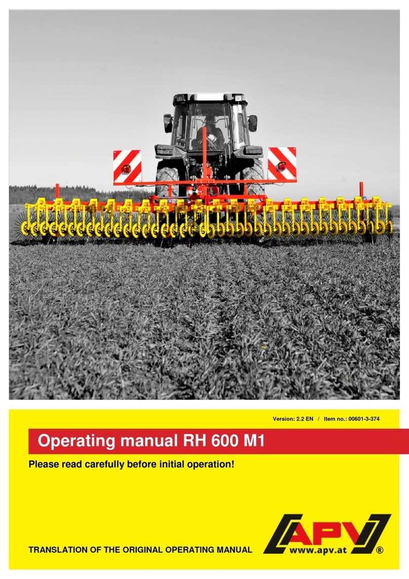
APV RH 600 M1 User manual

ROTARY HOE
RH 600 M1
OPERATING MANUAL
PLEASE READ CAREFULLY BEFORE INITIAL OPERATION!
Translation of the original operating manual
Version: 2.3 EN US; Item number: 00602-3-329

2
TABLE OF CONTENTS
1EC DECLARATION OF CONFORMITY..........................................................................................4
2IDENTIFICATION OF THE IMPLEMENT........................................................................................5
3SERVICE ........................................................................................................................................5
4GUARANTEE .................................................................................................................................5
4.1 Warranty activation..............................................................................................................6
5SAFETY INSTRUCTIONS ..............................................................................................................6
5.1 Intended use........................................................................................................................6
5.2 General safety information and accident prevention regulations ..........................................6
5.3 Attached implements ...........................................................................................................8
5.4 Hydraulic system..................................................................................................................9
5.5 Maintenance........................................................................................................................9
5.6 Tires...................................................................................................................................10
5.7 Attached seeders...............................................................................................................10
6INFORMATION SIGNS / HAZARD LABELS................................................................................11
6.1 Information signs................................................................................................................11
6.2 Hazard labels.....................................................................................................................12
7OPERATING MANUAL.................................................................................................................13
7.1 Structure and mode of operation........................................................................................13
7.2 Attachment on the tractor...................................................................................................13
7.3 Safe parking.......................................................................................................................14
7.4 Test folding........................................................................................................................14
7.5 Working position ................................................................................................................15
7.6 Quick-lift (factory-mounted)................................................................................................16
8MAINTENANCE AND CARE ........................................................................................................17
8.1 General maintenance instructions......................................................................................17
8.2 Instructions for regular maintenance..................................................................................17
8.3 Replacing star rings / bearings...........................................................................................18
8.4 Repair and corrective maintenance....................................................................................18
9INFORMATION ON NATURE CONSERVATION AND ENVIRONMENTAL PROTECTION.........18
10 TECHNICAL DATA.......................................................................................................................19
10.1 Combination possibilities RH 600 M1 with PS....................................................................20
11 HYDRAULIC SYSTEM DIAGRAM................................................................................................21
12 ROAD TRANSPORT ....................................................................................................................21
12.1 Transport on public roads (general instructions).................................................................21
12.2 Calculation of the weight ratios of axle loads on the tractor unit and ballast weights ..........22
12.3 Table of weight ratios.........................................................................................................23
13 LIGHTING CIRCUIT DIAGRAM...................................................................................................24
14 DECOMMISSIONING, STORAGE, AND DISPOSAL....................................................................24
14.1 Decommissioning the implement .......................................................................................24
14.2 Storing the implement........................................................................................................24
14.3 Disposal.............................................................................................................................25

3
15 CROP CULTIVATION TIPS WHEN USING THE ROTARY HOE..................................................25
15.1 Hitting the right growth phase.............................................................................................25
15.2 Applications .......................................................................................................................26
16 ACCESSORIES............................................................................................................................27
16.1 Mounting kit for PS 120 –300 on RS 600 ..........................................................................27
16.2 Accessories kit for dispersion plate installation RS600.......................................................27
16.3 platform kit.........................................................................................................................27
16.4 Lighting with warning signs (both sides).............................................................................28
16.5 Operating hours counter ....................................................................................................28
16.6 Accessories kit linkage sensor top link MX.........................................................................28
16.7 Sensor set –wheel sensor + linkage sensor for top link.....................................................28
17 SPARE PARTS.............................................................................................................................29
18 INDEX...........................................................................................................................................29

4
1EC DECLARATION OF CONFORMITY
in accordance with Machinery Directive 2006/42/EC
APV-Technische Produkte GmbH
Dallein 15
3753 Hötzelsdorf, Austria
hereby declares that the mounted implement described below complies with the relevant essential health
and safety requirements of the directives cited above by virtue of its design and construction and in the
configuration we have placed on the market.
If the mounted implement is modified without prior consultation with APV-Technische Produkte this
declaration shall lose its validity.
Designation of the mounted implement:
ROTARY HOE RH 600 M1
Serial numbers: from 07013-01000
Year of manufacture: from 2021
Relevant EC directives:
Directive on machinery –Machinery Directive 2006/42/EC
In the planning, design, construction, and placement on the market of the mounted implement Rotary
Hoe RH 600 M1, in addition to the directives, the following harmonized European norms have also been
applied, in particular:
EN ISO 12100:2010 Safety of machinery –General principles for design –Risk assessment and risk reduction
EN ISO 13857:2020 –Safety distances to prevent hazard zones being reached by upper and lower limbs
EN ISO 13849-1:2015 –Safety of machinery –Safety-related parts of control systems
Responsible for the technical documentation: Planning and Design department, Dallein 15
Dallein/Hötzelsdorf, on 08/2021
Ing. Jürgen Schöls
Managing Director
(Authorized person in the EU)

5
2IDENTIFICATION OF THE IMPLEMENT
The Rotary Hoe can be clearly identified through the following information on the type plate:
Designation
Model
Production number
Position of the type plate
The type plate is located on the main frame on the mounting frame bracket.
The illustration below (Figure 1) shows the structure of the type plate.
Figure 1
The information on the type plate has the
following meaning:
1: Designation
2: Model
3: Production number/serial number
4: Weight
5: Year of manufacture
NOTE!
Always specify your implement's production number/serial number for inquiries or warranty
claims.
3SERVICE
Contact us at our Service address in the following cases:
If in spite of the information in this operating manual you have questions concerning the handling of
the Rotary Hoe
To order spare parts
To commission service and maintenance tasks
Service address:
APV - Technische Produkte GmbH
HEADQUARTERS
Dallein 15
3753 Hötzelsdorf
AUSTRIA
Telephone: +43 2913 8001-5500
Fax: +43 2913 8002
Email: service@apv.at
Web: www.apv.at
4GUARANTEE
When taking delivery of the device, check it immediatelyfor any transport damage. Subsequent complaints
arising from transport damage can no longer be acknowledged.
Based on a warranty activation (see point 4.1), we provide a six-month factory warranty, starting from the
date of first use (your invoice is the warranty certificate).
This guarantee shall apply in the event of material or design errors and does not extend to parts that
become damaged through normal or excessive wear.
The warranty shall become null and void under the following circumstances,
If damage occurs due to external force.
In the event of an operating error.

6
If the kW/HP limit is significantly exceeded.
If the implement is altered, extended or fitted with third-party spare parts without our authorization.
4.1 WARRANTY ACTIVATION
Every APV implement must be registered immediately after delivery. The
registration activates the claim for warranty performances and thus APV can
guarantee the best service.
To activate the warranty for your implement, simply scan the QR code with your
smartphone –you will then be taken directly to the Service area of our website.
Of course, you can also activate the warranty through our website www.apv.at in the
Service area.
5SAFETY INSTRUCTIONS
This chapter contains general rules of behavior for proper use of the implement and safety
instructions that you must strictly comply with for your own safety.
The list isquite extensive, and some information does notjust pertain to theprovided implement. However,
the summary of the information will often remind you of safety rules that are unconsciously disregarded
when using the machines and implements in day-to-day work.
5.1 INTENDED USE
The implement has been built exclusively for customary use in agricultural tasks (intended use).
Any use that beyond this is non-intended use. The manufacturer shall not be liable for damage that is
incurred through non-intended use; the user alone bears the associated risk.
Intended use also includes compliance with the operation, service and maintenance conditions that are
prescribed by the manufacturer.
The implement must only be used, maintained, and repaired by people who are familiar with with the
implement and have been instructed with regard to the hazards. Ensure that all safety instructions are
passed on to other users as well.
The relevant, country-specific accident prevention regulations and other generally recognized safety,
occupational health and safety, and road traffic regulations must be complied with.
Unauthorized changes to the implement exclude any and all liability on the part of the manufacturer for the
resulting damage. This causes the Declaration of Conformity to lose its validity.
The Rotary Hoe is intended for outdoor operation in dry weather, within a temperature range from +5 °C
to 40 °C. Water ingress must be prevented. Do not use the Rotary Hoe in rainy conditions!
5.2 GENERAL SAFETY INFORMATION AND ACCIDENT
PREVENTION REGULATIONS
The operator must have read and understood this operating manual before handling the implement.
The owner must train and instruct their personnel. Personnel must have read and understood this
operating manual before handling the implement.
Always keep the operating manual in the vicinity of the implement for reference purposes.
When passing on the implement, ensure that you also pass on the operating manual.
Do not use the implement if you are tired or under the influence of drugs, alcohol or medications.

7
Each time before start-up check the implement and the tractor for road safety and operational safety
(e.g. defective parts, connections, fixations, hoses, guards, etc.)!
Before each use, the folding device and its securing devices (securing chain) must be checked for
proper function and effect.
Inspections must be performed before, during, and after use; care and maintenance of the implement
must be performed on a regular basis.
Comply with the generally valid safety regulations and accident prevention regulations of the
respective country!
This implement must only be used by persons who are informed of the danger zones and who are
familiar with the regulations for transport on public roads.
The warning and information signs affixed on the implement provide important instructions for safe
operation. Do not remove the warning and information signs under any circumstances. Comply with
the warning and information signs for your own safety!
Comply with the applicable country-specific road traffic regulations when using public roads!
Before beginning work, familiarize yourself with all the devices, activating elements, and their
functions. It is too late to do so during work implementation!
The user should wear close-fitting clothing! Avoid wearing loose clothing!
Keep the implements clean to prevent a fire hazard!
Check your immediate surroundings (check for children!) before start-up! Ensure sufficient visibility!
Carrying passengers while working and transporting them on the implement are prohibited!
Climbing onto the implement is only allowed if a platform kit is installed.
When using the platform kit, ensure that the implement is at a standstill, that it is also unfolded, and
lowered onto the ground.
Transporting work materials on the implement is prohibited!
Properly hitch the implement and fasten only to the prescribed fixtures!
Special care is required when coupling implements onto the tractor or uncoupling them from the
tractor!
When mounting the implement, the operator must particularly proceed in compliance with the tractor
requirementsas stipulated in the operating manual, andthe operator must ensurethat the connections
are properly established as specified in the operating manual.
Bring the support devices into their respective positions when mounting and dismounting the
implement (stability)!
Always install the weights properly at their designated fastening points!
Pay attention to the permissible axle load, total weight, and transport dimensions!
Check and install transport equipment, such as lighting, warning devices, and any protective devices!
Release parts for fast couplers must be freely suspended, and they must not release on their own in
the low position!
Never leave the driver's platform while while implement and tractor are in motion!
Handling, steering, and braking capability are also affected by mounted or attached implements and
ballast weights. Consequently, ensure that there is adequate steering and braking capability!
Take into account thewide load and/orthe implement's oscillating mass when turning! Attention tractor
curve!
Only operate the device when all protective devices are installed and in the protective position!
Do not position yourself in the work area!
Do not position yourself in the implements turning and swivel range!
Hydraulic folding frames must only be activated if no one is in the swivel range.
There are crushing and shearing points on power-operated parts (e.g. hydraulically-operated parts)!
Always ensure that your have a secure, safe stance when using implements with manual folding!
For high-speed implements with ground-drive tools –the oscillating mass that continues running
poses a hazard after lifting-out! Only approach implement after it has come to a complete standstill!
Before exiting the tractor, park the implement on the ground, turn off the engine and remove the
ignition key!
Do not allow anyone to enter the area between the tractor and implement without securing the vehicle
from rolling off via the parking brake and/or the wheel chocks!

8
Secure the folded-in frame and lift-out units in transport position!
Swing in and lock the packer catch arms before road transport!
Lock the track marker in transport position!
The Rotary Hoe may only be used on agricultural land. It must not be used on normal road surfaces,
on asphalt or concrete. In particular, the Rotary Hoe must not be used in the building industry on
construction sites, for winter service, for road construction, or for underground mining.
When driving on roads, which is only permitted with folded-in side wings and the Rotary Hoe lifted,
the tractor hydraulic system prevents lowering of the Rotary Hoe as well as lowering of the folded up
components (additionally secured with a chain), and does this even if the tractor hydraulic system
fails.
The specifications in the operating manual regarding mounting as well as the calculation of the weight
ratios and the axle loads of the tractor must be complied with.
There must be no other persons in the hazard area of the Rotary Hoe. The driver must perform a
visual inspection!
Always keep hands, clothing etc., away from rotating parts!
According to the operating instructions, the tractor vehicle speed must be maintained between 2 and
25 km/h when performing work operations.
Do not transport people on the Rotary Hoe during intended use on agricultural land or when driving
on roads.
A clear view of the mounted Rotary Hoe and the hazardous movement area is required to monitor the
procedure.
Do not work under the implement –especially when it is lifted.
Safety goggles and hearing protection must be used.
Ensure that the hydraulic couplings are not soiled.
When driving under low obstructions or through narrow obstructions (e.g. power lines, underpasses,
etc.), pay attention to the height and width of the implement to avoid collisions.
If implement parts are lost or broken, they must be immediately replaced with original parts by trained
specialist personnel.
Accessories must be properly mounted in compliance with standards by qualified specialists from an
appropriately authorized company.
When implement parts are moving (e.g. during the folding or pre-loading procedure) ensure that no
one is standing in the danger zone of the implement –there is a risk of crushing.
During mounting, the operator must particularly ensure compliance with tractor requirements
regarding power, axle loads, and weight distribution as stipulated in the operating manual, and the
operator must ensure that the connections are properly established as specified in the operating
manual.
The operator must regularly check the implement (before each use) for breakage, cracks, abrasion
points, leaks, loose bolts and threaded connections, vibrations, abnormal noises, and properfunction.
The implement must not be used during storms and rain, it must be parked under a roofed shelter.
The operator must ensure that no one is standing near the Rotary Hoe when it or its components are
moved via the tractor hydraulic system. The driver/operator must perform a visual inspection!
Secure the implement to prevent it from rolling off!
5.3 ATTACHED IMPLEMENTS
Before mounting and dismounting implements on the three-point linkage, bring the operating devices
into the proper position that prevents unintentional lifting or lowering!
For three-point mounting, the attachment categories for the tractor and implement must match or be
agreed!
There is a risk of injury due to crush and shear points in the three-point linkage area!
Do not step between the tractor and implement when activating the external control operating unit for
the three-point attachment!
Always ensure that the tractor three-point linkage is adequately arrested on the side when the
implement is in transport position!
For road travel with lifted implement, the operating lever must be locked to prevent lowering!

9
When mounting the implement, the operator must ensure that there is a metallic connection (ensured
by the lower link) established with the tractor.
The operator must ensure that the implement cannot lower when driving on roads (shut-off valve on
the tractor's hydraulic system or similar safeguard).
When driving on roads, which is only permitted with the implement lifted and with folded side frames,
the control block on the hydraulic cylinder prevents lowering of the implement and lowering of the
folded-up side frames (additionally secured with a chain). The hooked-in chain also prevents
accidental lowering of the side frame in road transport in the event that the tractor hydraulic system
fails.
Mounting of any accessories on the implement must be executed in accordance with standards. The
maximum permitted mounted weight / total weight of the implement must not be exceeded.
Only APV machines and accessories may be mounted on the implement.
5.4 HYDRAULIC SYSTEM
The hydraulic system is under high pressure!
Ensure that the hydraulic hoses are connected as prescribed when connecting hydraulic cylinders
and hydraulic motors!
When connecting the hydraulic hoses to the tractor hydraulic system, ensure that the hydraulics on
both tractor and implement are depressurized!
For hydraulic function connections between tractor and implement, coupling sleeves and coupling
connectors must be marked so that the possibility of operating error can be excluded! Swapping the
connections reverses the function (e.g. lifting/lowering) –risk of accident!
Regularly inspect hydraulic hose lines and replace them if they are damaged or ageing! The
replacement hoses must meet the technical requirements specified by the implement manufacturer!
Due to the danger of injury, use the appropriate aids when looking for leaks!
Liquids that escape under high pressure (hydraulic oil) can penetrate the skin and cause severe
injuries! If there are injuries, seek medical attention immediately! (Danger of infection!)
Before tasks on the hydraulic system, set down the implement, depressurize the system, and turn off
the engine!
Only detach the securing chains after they have been slackened! (The cylinder must be filled with oil).
The operator must carefully and cleanlyestablish the connections to thetractor hydraulic system when
installing the implement.
5.5 MAINTENANCE
Always perform repair, maintenance, and cleaning tasks, and eliminate malfunctions when the drive
is switched off, the engine is at a standstill, and the implement has been uncoupled from the towing
vehicle! Remove the ignition key! Check to ensure de-energized status!
The maintenance tasks themselves must only be performed by trained specialists and must never be
performed alone. The utmost caution is required when replacing defective components or tools.
The mounted implement must always be disconnected from the towing vehicle for service or
maintenance tasks. If repairs or maintenance tasks are required on the implement that can only be
performed in conjunction with the towing vehicle, these tasks must be identified by a clearly visible
information sign "Caution: Maintenance Work".
Regularly check nuts and bolts for firm seat and retighten if necessary!
When performing maintenance tasks on the raised implement, always prevent it from lowering by
means of appropriate support elements!
Use suitable tools and gloves that are cut-resistant when replacing work tools with sharp edges!
Components that cannot be removed with tools, such as a screwdriver or wrench, may only be
replaced by qualified specialists from an appropriately authorised company or by APV Customer
Service.
Properly dispose of oil, grease, and filters in accordance with local regulations!
Always disconnect the power supply before working on the electrical system!

10
Disconnect the cables on the generator and battery when performing electrical welding tasks on the
tractor and attached implements! The repair points must be cleaned (risk of ignition if there is fouling)!
Spare parts must at least meet the technical requirements specified by the implement manufacturer!
Original parts meet these requirements!
Only universal joint shafts prescribed by the manufacturer can be used!
The guard tube and guard funnel for the universal joint shafts as well as the PTO shaft guard –also
on the implement side –must be installed and they must be in proper condition!
For universal joint shafts, pay attention to the prescribed tube covers in transport position and working
position!
The universal joint shaft must only be mounted and dismounted when the PTO shaft and the motor
are switched off and the ignition key is removed!
Always ensure that the universal joint shaft is properly mounted and secured!
Prevent the universal joint shaft guard from rotating simultaneously with the shaft by hooking in the
chain!
Before switching on the PTO shaft, ensure that the selected PTO shaft speed of the tractor matches
the permissible speed of the implement!
When using the ground speed PTO, ensure that the rpm is forward speed-dependent and that the
direction of rotation is inverted when driving in reverse!
Before switching onthe PTO shaft, ensurethat no one is standing in the danger zone ofthe implement!
Never switch on the PTO shaft when the motor is switched off!
When working on the PTO shaft, ensure that no one is standing in the area of the rotating PTO shaft
or universal joint shaft!
Always switch off the PTO shaft if excessive angular deflection occurs and it is not required!
Caution is required after switching off the PTO shaft: Danger due to the centrifugal mass that is still
rotating!
Do not get too close to the implement during this time. Work can only be performed after it comes to
a complete standstill!
Cleaning, lubricating or adjusting the implement or universal joint shaft driven by the PTO shaft must
only be performed when the PTO shaft and motor are switched off and the ignition key is removed!
Place the uncoupled universal joint shaft on the prescribed holder!
After dismounting the universal joint shaft, fit the protective cover onto the PTO stub!
If damaged, it must be replaced immediately before working with the implement!
If necessary, use additional lighting (e.g. hand lamp) for repair or maintenance tasks.
The implements should be regularly lubricated and cleaned (outdoors) using water or compressed air.
While doing this, personal protective equipment must be worn if necessary.
Maintenance and cleaning tasks must be carried out with the implement lowered, engine switched off,
and secured to prevent it from being switched on again.
We recommend a cleaning in accordance with the maintenance instructions. In this regard you must
proceed as specified in the maintenance manual and protective equipment must be used. The Rotary
Hoe must be cleaned with water (no high-pressure cleaner) or compressed air.
5.6 TIRES
For tasks on tires, ensure that the implement has been safely parked and secured against rolling off
(wheel chocks).
Installing wheels and tires requires adequate knowledge and the prescribed installation tools!
Repair tasks on the tires must only be performed by specialists and with the appropriate assembly
tool!
Regularly check the tire pressure! Pay attention to the prescribed air pressure!
5.7 ATTACHED SEEDERS
When using a seeder, all the instructions provided by the implement manufacturer must be complied
with.

11
The seeder can be reached easily via a ladder and a platform. The ladder and platform must be clean
and dry for use.
While driving, it is strictly prohibited to stand on the platform or on its access ladder.
When not in use, the ladder must be swung upward and secured.
A ladder must be made in conformance with standards. This ladder is available from APV.
5.7.1 FILLING THE SEEDER
The seeder is filled using a supply vehicle.
The platform kit must not be used to fill the seeder or used as a storage area for objects or seed.
When filling the seeder, never stand under a suspended load!
When driving up to the implement with seed, ensure that no one is standing on or around the
implement.
During the loading procedure, avoid any contact with the treated seed; wear gloves, a dust mask, and
safety goggles.
CAUTION!
Printing errors excepted, all information without guarantee.
6INFORMATION SIGNS / HAZARD LABELS
Pay attention to these stickers on the implement; they warn of particular hazards!
6.1 INFORMATION SIGNS
Read and comply with
the operating manual
before start-up!
Only lift the implement
off of the ground slowly!
Loading hook.
Fasten the cable or
chains here when
loading the implement!
Retighten all bolts and
nuts after brief use.

12
Carefully read the
operators manual prior
to operating. Observe all
operating and safety
warnings!
Do not position yourself
in the danger zone
(swivel area)!
6.2 HAZARD LABELS
Caution, crushing area!
Never reach into the
crush hazard zone as
long as parts are
moving in this zone!

13
7OPERATING MANUAL
7.1 STRUCTURE AND MODE OF OPERATION
Thanks to its robust and compact design, the Rotary
Hoe RH 600 is ideal for controlling undesired mulch
plants (weeds) in various crops.
The rotating hoe rings bury or uproot the mulch plants,
promote tillering of the crop, and bring oxygen into the
soil. The slanted position of the rings increases
efficiency and makes the implement even more
aggressive. The rotating rings prevent the implement
from clogging and makes it possible to comb out the
weeds.
The Rotary Hoe is insensitive to organic residues; this
makes it highly suitable for mulch seeding.
The work is performed byspring steel pins, 6 mm thick,
which are cast in a slanted polyurethane disc. These
star rings 50 cm in diameter are individually suspended
and they can individually adapt to ground
Figure 2
1: Cat II three-point linkage
2: Parking supports
3: Star rings
unevenness. The downward pre-load force occurs via the net weight of the ring, added to the pre-load
force of the springs. Thanks to the toolless quick-release fastener on each arm, it is possible to adjust the
pitch from 0 –30° in 5° increments.
Because the working rings are arranged back-to-front, starting from the middle, lateral pulling forces do
not occur. To ensure full area tillage, the middle ring is slightly set back, this prevents the two rings in the
middle from interlocking, which would damage the crops.
7.2 ATTACHMENT ON THE TRACTOR
The implement must be mounted on the tractor's 3-point linkage.
The lifting struts must be adjusted at the same height on the left and right.
Hook in the top link in such a manner, that the top link is also inclined toward the tractor in work operation.
(Comply with the information provided by the manufacturer of the tractor.)
Adjust the side linkage so that the implement can oscillate freely in the field but becomes fixed in place in
lifted-out status.
Additional wheel weights can be advantageousfor difficult operating conditions. See the operating manual
provided by the manufacturer of the tractor.
To ensure steering and braking capability, the tractor must be adequately equipped with ballast weight on
the front. At least 20% of the unladen vehicle weight is required on the front axle.

14
7.3 SAFE PARKING
To ensure safe parking of the implement, lower the parking
support and the two feeler wheels on the center frame, as shown
in Figure 3.
Figure 3
7.4 TEST FOLDING
Connect the hydraulic lines to the towing vehicle, and ensure that the connections are clean to prevent
contamination in the oil.
Actuate the control unit to fill the cylinder with oil. The cylinder is filled as soon as the securing chains are
offloaded. Unhook the securing chains and hook them in on the other end of the chain. Ensure that no one
is in the danger zone and only fold the implement when it is lifted off of the ground.
The implement must also be lifted off of the ground when it is folded into transport position. Do not forget
to hook-in the securing chains and close the stop tap.
When uncoupling the implement, you must offload the hydraulic hose through the float position before
pulling it out.
CAUTION!
Before unfolding the machine, always ensure that the securing chain is unhooked. If the
implement is unfolded with the securing chain hooked in, the machine can be irreversibly
damaged or the securing chain and its direct components can at least be initially damaged, which
can result in failure when the chain is later loaded to capacity. Consequently, the securing chain
must always be replaced after a faulty / incorrect folding procedure!
CAUTION!
Before folding the implement, the
four arms left and right of the
pivot point must be in working
position. Risk of collision with
the arms when they are folded
up!
Figure 4
1: Pivot point of the folding
2: These 2 + 2 arms must ALWAYS be in working position before
they are folded up!

15
7.5 WORKING POSITION
Adjustment of the working depth, i.e. the regulating effect, occurs via the support wheels,
the pre-load of the spring, the adjustment of the pressure angle of the star rings, and the
forward speed. The contact pressuremust not be increasedvia the top link!In this regard,
it must be stated that the frame of the implement must be adjusted horizontally.
Figure 5
7.5.1 ADJUSTMENT OF THE PRE-LOAD FORCE PER ARM
The pre-load force is increased / reduced by releasing the quick-release
fastener and adjusting the spring pre-load through the hole pattern.
In order to actuate the quick-release fastener for adjustment of the pre-
load force, the clamping mechanism must be released. This is done by
pressing the spring-loaded bolt, which clamps the quick-release fastener
onto the hollow profile.
This releases the quick-release fastener and it can also be turned
downward and out of the way if there is a lack of space.
Thanks to the handle, the pre-load plate of the spring can be adjusted up
or down in the 2nd step. When the pre-load plate is pulled out, the pre-
load force on each ring increases. When the pre-load plate is pushed in,
the pre-load force is reduced.
In the last step, the quick-release fastener must be pulled forward again
and the clamping mechanism must be released.
Figure 6
1: Pre-load platewith handle
2: Quick-release fastener
7.5.2 ADJUSTING THE PITCH
Press the quick-release fastener lever forward (in the
direction of travel) to unlock the ring fastening.Turn the
arm holder to adjust the pitch of the ring. The angle is
adjusted by 5 degrees with each locking notch. The
ring is again fixed in place by releasing the lever.
Figure 7: Pitch for both rings 30°
1: Fastening lever
2: Locking notch
3: Ring holder
Fig. 8: Pitch 30° and 0°

16
7.6 QUICK-LIFT (FACTORY-MOUNTED)
Use the quick-lift to adapt the implement to the crop without tools;
here only the folded-up arm must be fixed in place with the pin in
the top hole. If the quick-lift is not active, the pin can be stored in
the parking position inthe last hole. Likewise, the downward swing
range for the arm can be limited by inserting the pin in the second
hole from the bottom.
The ground clearance is 290 mm when the arm is lifted. By folding
up the arm, a width of approx. 150 mm will not be worked.
Figure 9
1: Arm
2: Pin for quick-lift
Fig. 10: Pin in parking position
Fig. 11: Quick-lift –lifted-out position
Fig. 12: Negative range limitation
The mounted plate (see Figure 13) prevents misuse. Thus the quick-
lift cannot be used as a lifting accessory for the work elements.
Figure 13: Installed plates to prevent misuse
CAUTION!
Before folding the implement, the four arms left and right of the
pivot point must be in working position. Risk of collision with
the arms when they are folded up!
CAUTION!
The quick-lift MUST NOT be used as a lifting accessory!

17
8MAINTENANCE AND CARE
8.1 GENERAL MAINTENANCE INSTRUCTIONS
To maintain the implement in good condition even after a long service life, comply with the following
instructions:
In Point 5, you will find some basic safety regulations for maintenance tasks.
Original parts and accessories are specifically designed for the machines, i.e. implements.
We expressly state that parts and accessories that are not delivered by APV are also neither tested
nor approved by APV. Consequently, installing and/or using such products can negatively alter or
affect the prescribed design characteristicsof your implement. The manufacturer cannotbe held liable
for damage that occurs due to use of non-original parts and accessories.
Unauthorized modifications, as well as use of components and add-on parts on the implement that
are not purchased from APV, exclude any and all liability on the part of the manufacturer and render
the CE Declaration of Confomity null and void.
Check the hydraulic hoses for wear, damage, and ageing before every start-up. Damaged or
faulty parts must be replaced immediately.
When replacing the hydraulic hose lines, original spare parts must be used that meet the technical
requirements specified by the implement manufacturer.
Caution! Liquids escaping under high pressure can penetrate the skin. Consequently, seek medical
attention immediately if there is an accident!
Lubricate alllubrication points after cleaning, anduniformly distribute thelubricant in the bearing points
(e.g. perform a brief test run).
For implements with fast coupler, the guide slots must also be lubricated.
Do not use a high-pressure cleaner to clean bearing parts and hydraulic parts.
Cleaning with excessive pressure can damage the paint.
Use environmentally-friendly agents to protect the implement from rust during the winter.
Park the implement in a place where it is protected from the weather.
Park the implement in a manner that prevents an unnecessary load on the tine wheels.
Hydraulic hose lines must be replaced at the latest 6 years after their manufacturing date. The
manufacturing date of the hydraulic hose lines is specified on the press fittings.
Park hydraulically folded, and also mechanically folded implements in a folded state only.
The hydraulic system must be inspected at least once a year by a qualified specialist.
8.2 INSTRUCTIONS FOR REGULAR MAINTENANCE
Retighten all bolted connections no later than after 3 operating hours, then repeat the process after
approx. 20 operating hours, and perform regular inspections afterwards. (Loose bolts can cause
significant secondary damage that is not covered by the guarantee.)
After the first 10 operating hours and every 50 operating hours thereafter, check the hydraulic units
(hoses and couplings) as well as pipeline for leaks and retighten the threaded connections, if
necessary.
All implement parts must be regularly checked for operational capability (appearance and handling).
Occasionally check the tire pressure (approx. 2.1 bar).
The platform kit and its access ladder must be visually inspected on a regular basis.
The rubber for fixation of the access ladder of the platform kit must be checked regularly for wear and
replaced if necessary.
Regularly lubricate the lubricating nipples on the fold points (with multipurpose grease approx. every
10 operating hours).

18
CAUTION!
The bearings on the arms are maintenance-free bearings; do not
lubricate these bearings.
Figure 14
8.3 REPLACING STAR RINGS / BEARINGS
Replace worn or broken star rings:
Unscrew the hex bolt.
Take off the ring, including the bearing and the black fastening discs.
Now take the new star ring.
Assembly occurs in the reverse order.
Figure 15
Replace bearing:
Unscrew the 6 hex nuts.
Take off the black fastening discs and press out the bearing.
Now take the new bearing.
Assembly occurs in the reverse order.
Figure 16
8.4 REPAIR AND CORRECTIVE MAINTENANCE
Contact the manufacturer if the implement fails or is damaged. The contact data is provided in chapter 3.
9INFORMATION ON NATURE CONSERVATION AND
ENVIRONMENTAL PROTECTION
Reduction of noise exposure in use
Any loose parts (such as chains) should be fastened to avoid unnecessary noise.
Energy-efficient use
The tine wheels of the implement should not penetrate into the field deeper than necessary. This ensures
that the load on the towing vehicle is no more than is strictly necessary and fuel can be saved.

19
Recyclable raw materials and disposal
Many parts of the implement are made of steel or spring steel (such as the center frame, side frame, etc.)
and can be removed and recycled by a waste disposal company.
10 TECHNICAL DATA
type designation
RH 600 M1
Mode of operation
1 row of star rings
Working width [m]
6
Transport width [m]
2.85
Dimensions (L x W x H) folded [m]
1.65 x 2.85 x 2.75
Working speed [km/h]
2 –25 (depending on crop)
Working depth [mm]
0 –30
Star rings [units]
40
Line spacing of the star rings [mm]
150
Angle of inclination [°]
0 –30 (adjustable in 5° increments)
Feeler wheels (standard equipment)
[units]
4
Attachment/suspension (three-point,
etc.):
Cat II
Hydraulics
Double-acting control unit
Net weight [kg]
750
Work tools
Star rings with wire nail inserts Ø 6 mm
Star ring Ø 500 mm
Ground adaptation
Individual suspended star rings
Ground adaptation occurs via a compression spring
Minimum tractor performance
48 kW / 65 HP
Can be equipped with:
PS 120 M1, PS 200 M, PS 300 M1 with electric / hydraulic
fan

20
10.1 COMBINATION POSSIBILITIES RH 600 M1 WITH PS
PS
PS 120 E
PS 120 H
PS 200 E
PS 200 H
PS 300 E
PS 300 H
PS dimensions
LxWxH [cm]
80x60x90
105x60x90
90x70x100
110x70x100
100x80x110
150x80x110
PS weight [kg]
45
68
60
83
70
93
PS and RH
RH 600 M1
PS 120 E
RH 600 M1
PS 120 H
RH 600 M1
PS 200 E
RH 600 M1
PS 200 H
RH 600 M1
PS 300 E
RH 600 M1
PS 300 H
Part for
mounting
Transport
dimensions for RH
and PS combined
LxWxH [m]
1.65x2.85x2.75
1.65x2.85x2.75
1.65x2.85x2.75
1.65x2.85x2.75
1.65x2.85x2.75
1.65x2.85x2.75
Mounting kit for
PS 120-300
Weight of RH and
PS combined [kg]
795
818
810
833
820
843
Fig. 17: RH from above
Fig. 18: PS from above
W: Width
L: Length
Other manuals for RH 600 M1
2
Table of contents
Other APV Farm Equipment manuals

APV
APV Grassland Combi User manual

APV
APV LF 600 M1 User manual

APV
APV Grassland harrow GS 300 M1 Operational manual

APV
APV ES 100 M1 Classic Installation instructions

APV
APV Tined Weeder Pro VS 600 M1 User manual

APV
APV GW 400 M1 User manual

APV
APV PS 800 M1 Operational manual

APV
APV Tined Weeder Pro VS 150 M1 User manual

APV
APV ZS 200 M3 User manual

APV
APV AS 300 M1 User manual