Aqua DGTEC CD Instructions for use

DGTEC Model INSTRUCTION AND MAINTENANCE MANUAL
Programmable digital peristaltic pump ENGLISH
ADSP7000634 rev. 1.3 23/09/2020 1/36
DGTEC
Model CD

dGdoser Model INSTRUCTION AND MAINTENANCE MANUAL
Programmable digital peristaltic pump ENGLISH
ADSP7000634 rev. 1.3 23/09/2020 2/36

dGdoser Model INSTRUCTION AND MAINTENANCE MANUAL
Programmable digital peristaltic pump ENGLISH
ADSP7000634 rev. 1.3 23/09/2020 3/36
CONTENTS
1.0 INTRODUCTION ……………………………………….…………………………………………………………………………..…………… 4
1.1 Warnings …………………………………………………………………...………………………….……………….......………………. 4
1.2 Standards of reference …………………………………………………………………………………………………………………….. 4
1.3 Technical features ….. ……………………………………………………………………………………….….......…………………….. 5
1.3.1 Electrical features……………………….………………………………………………………………….…………………….. 5
1.3.2 Performance …………….……………………….……………………………………………………………………………… 5
2.0 INSTALLATION ………………………………………………………………………………………………….……………………………… 5
2.1 General rules………. …………………………………….………………………….…………………………………..….……………….. 5
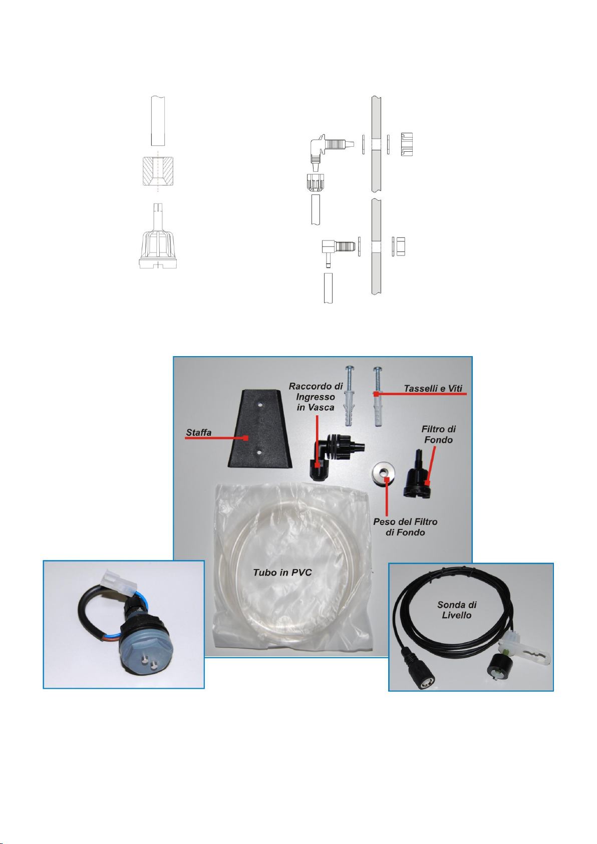
2.2 Installation kit…..……………………………………………………….……………………..……………………………….……………… 5
2.3 Assembly…………….………………………………………………………………………….……………………….…………..………… 7
2.3.1 Conductivity probe connection ……………………………………………………………………….…………………………... 7
2.4 Electrical connections …………………….………..………………………………………………………..……………….……………… 8
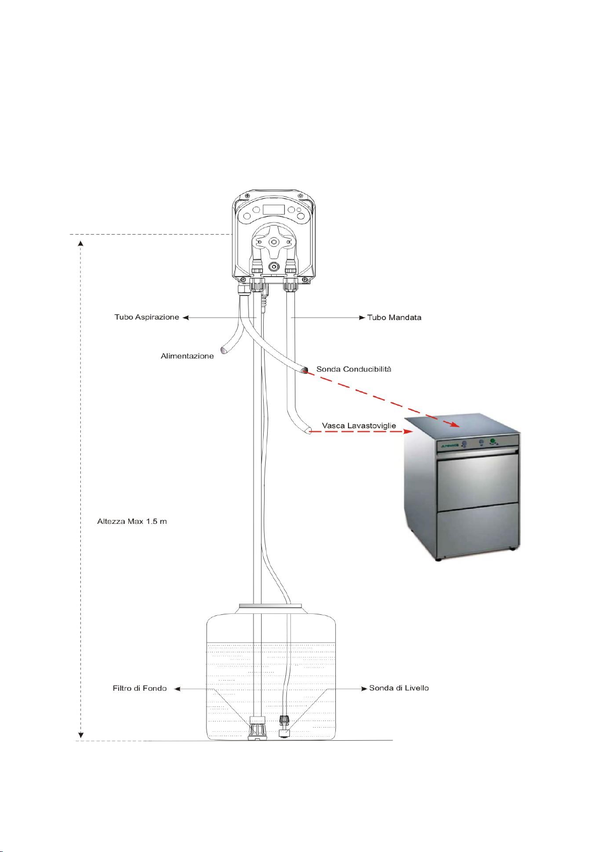
2.5 Hydraulic connections. ………..…………………………………………………………………………………………………………….. 9
2.5.1 Installation for dosing liquid detergent ……………………………….………………………………………………………….. 9
2.5.1 Installation for dosing solid detergent ……………………………….…………………………………………………………… 10
3.0 PROGRAMMING ………..………..……..……………………….……………….………………………………………................................ 11
3.1 Main Features ……………..….…………………………………………..…………...………………………….…………………………..11
3.2 Quick Start-Up ………….………………………………………………….……………………………………..…………….……………..14
3.3 Advanced Programming……………………………..………………………………………………………………………………………. 15
3.3.1 Setting the Language……………………………..………………………………………………………………………………… 15
3.3.2 Setting the Set-point ……………………………………………………………………………………………………………….. 15
3.3.3 Displaying and Resetting Statistics ………………………………………………………………………………………………. 16
3.3.4 Setting the Temperature ………………………………….………………………………………………………………………. 17
3.3.5 Pump Calibration ………… ……………………………………………………………………………………………………….. 17
3.3.6 Resetting Default Parameters………………………………………………………………………………………………………18
3.3.7 Settings Menu………………………………………………………………………………………………..…..………………….. 18
4.0 ALARMS …………………………..…………………....…………………………………………………………………………..………..…… 19
4 1 Motor Alarm……………………………..…………………………………………………………………..………………………………… 19
4.2 Maintenance Alarm……………………………..………………………………………………………………….…………………………. 20
4.3 Level Alarm ……………………………..……………………………………………………………….…………………..……………….. 20
4.4 OFF Status Alarm……………………………..…………………………………………………………………..…………………………. 20
4.5 OFA Alarm……………………………..…………………………………………………………………..……………..…………............... 21
4.6 Temperature Alarm…………………………………………………………………………………………………………………………… 21
5.0 MAINTENANCE …………………………………..…………………….………..…………………………………………..………………….. 21
5.1 General Rules …….…………………………………………..…………………………………………………………………………….. 21
5.2 Periodic Maintenance………….…………….………………………………………………….…………………………………………... 21
5.3 Troubleshooting ………………….….…………………………………..…………………………………………………………………… 23
6.0 RETURNING MATERIAL TO THE AFTER-SALES
SERVICE………………………..……………………..…………………………………………………………………………………………………… 24
7..0 WARRANTY CERTIFICATE ………..………..………………………………………….……………….……………………………..……… 24
8.0 ATTACHMENTS ………………………..………………………………………………………………………………………………………. 25
ATTACHMENT A –OVERALL DIMENSIONS………………………………………………………………………………………………… 25
ATTACHMENT B –REFERENCE FIGURES………………………………………………………………………………………………….. 26
ATTACHMENT C –EXPLODED VIEWS………………………………..……………………………………………………………………… 27
ATTACHMENT D –CHEMICAL COMPATIBILITY TABLE……..…………………….……………………………………….………………29
ATTACHMENT E –DEFAULT PARAMETERS ………..…..………………………………………………………………………………….. 31
ATTACHMENT F –ACRONYM TABLE …….………..…..…………………………………………………………………………………….. 32
ATTACHMENT G –MENU LAYOUTS…. …….………..…..…………………………………………………………………………………… 33

DGTEC Model INSTRUCTION AND MAINTENANCE MANUAL
Programmable digital peristaltic pump ENGLISH
ADSP7000634 rev. 1.3 23/09/2020 4/36
1.0 INTRODUCTION
The range of “DGTEC” programmable digital peristaltic pumps is designed to manage dishwashers and consists of
the following models:
ST Model: single solenoid valve programmable digital pump
2ST Model: double solenoid valve programmable digital pump
CD Model: adjustable digital pump with conductivity reading
The CD model is designed to dose liquid or solid detergents according to the conductivity measured in the
dishwasher tank, thus enabling simple and precise adjustment.
1.1 WARNINGS
Before starting assembly, carefully read these instructions and follow them during installation.
If the instructions reported in this manual are not followed or carried out correctly, this may result in
personal injury or damage the device and/or systems.
We recommend reading the label reported on the pump and following the directions below:
The pressure of the injection point must be lower or equal to the pump's rated value!
When you receive the product, check the integrity of the pump and all of its parts. Should there be
any anomalies, promptly notify qualified personnel before performing any operations.
Keep this manual carefully for future reference.
Before installing the pump make sure that the details provided on the adhesive plate attached to
the pump correspond to those of the electrical system.
Do not handle the equipment with wet hands or feet!
Do not leave the equipment exposed to the elements!
Make sure the peristaltic tube is compatible with the liquid to be dosed!
The equipment must be handled by qualified personnel!
If any irregularities are experienced during pump operation, cut off the power supply and contact
one of our customer care centres for any repairs!
In order for the pump to operate correctly it is necessary to use original spare parts or accessories.
The manufacturer is relieved of any responsibility in the case of any breakdowns due to tampering
or use of non-conforming parts and accessories
The electrical system must comply with regulations in force in the country where the system is
installed.
The operating ambient temperature must not exceed 40°C with a relative humidity of 90% at 90°C.
1.2 NORMATIVE REFERENCES
Our pumps are manufactured according to General Standards in force and in compliance with the following
European Directives:
n° 2014/30/CE “ E.M.C.
n° 2014/35/CE “DBT Low Voltage Directive”
n° 2011/65/UE , 2012/19/UE “direttive RoHs e WEEE”

ADSP7000634 rev. 1.3 23/09/2020 5/36
1.3 TECHNICAL FEATURES
1.3.1 ELECTRICAL FEATURES
For the power supply value we recommend reading the label on the pump!
1.3.2 PERFORMANCE
Maximum height of the suction tube: 1.5 m
Flow rate and back-pressure: refer to Table 1, read the label on the pump to identify the corresponding
model.
Codes
Power supply
Motor
Type
Flow
rate (l/h)
Backpressure
(bar)
Peristaltic
Tube
PT100
ADD400601C000000
(not available)
24 VAC/VDC
24 VDC
6
1
Santoprene
X
ADD4006010000000
230 VAC
24 VDC
6
1
Santoprene
X
ADD401000C000000
(not available)
24 VAC/VDC
24 VDC
10
0
Santoprene
X
ADD4010000000000
230 VAC
24 VDC
10
1
Santoprene
X
Tab. 1
The pump codes that may be ordered are found in the table. The manual also proposes pumps with unavailable
characteristics in the 4 models in the table (conductivity probe with PT100 sensor to read the temperature and 24
VDC output to activate the solenoid valve to dose solid detergent).
Operating ambient temperature: 0 ÷ 45°C
Transport and Packaging Temperature: -10 ÷ 50°C
Protection rating: IP65
2.0 INSTALLATION
2.1 GENERAL RULES
Pump installation must be carried out as follows:
In vertical position with an uncertainty not greater than +/-15°.
Away from sources of heat in dry locations, at a maximum temperature of 40°C and a minimum of 0°C.
In a ventilated environment and easily accessible to an operator for periodic maintenance.
Above the level of the liquid that needs to be dosed, at a height of 1.5 metres maximum.
Do not install the pump above the tank when using liquids that emit fumes, unless it is sealed shut.
2.2 INSTALLATION KIT
When you purchase the pump, it includes everything required for correct installation, specifically:
Bracket;
Dowels and screws;
Level probe (optional);
Foot strainer (see Fig. 1- a);
PVC suction and delivery tubes (4 m.);
Conductivity Probe and Electrodes;
Tank inlet fitting (see Fig. 1- b);

ADSP7000634 rev. 1.3 23/09/2020 6/36
Fig. 1
Foot strainer Tank inlet fitting
(a)
(b)
The full kit supplied is reported in Figure 2.
Fig. 2- Installation kit

ADSP7000634 rev. 1.3 23/09/2020 7/36
2.3 ASSEMBLY
We always recommend wearing protective masks, gloves, goggles and any other PPE during all
installation steps and when handling chemical products.
WALL MOUNTING
Proceed as follows to secure the pump to the wall:
Fix the bracket to the wall using the plugs and screws supplied.
Place the pump on the bracket.
Ensure the fixing is stable.
It is also recommended to install the pump in a dry environment, away from heat sources and
exhaust vapour.
2.3.1 CONDUCTIVITY PROBE CONNECTION
The provided conductivity probe is a 2-wire conductivity meter type. Upon request, it is possible to receive a 4-wire
temperature-compensated probe. The codes set out in Tab. 1 do not consider this option.
Fig. 3 Conductivity Probe
Fig. 4 - Conductivity card
To carry out correct installation of the conductivity probe onto the dishwasher, verify the points detailed hereunder:
install the probe in the washing tank;
the probe electrodes must be at least 4 centimetres below the maximum filling level;
install the probe close to the washing pump filter;
Do not install the probe close to edges, electrical resistance, detergent input and at the bottom
of the tank.
Should the dishwasher not be predisposed to assemble the conductivity probe, make
a 23 mm hole in the washing tank wall.

ADSP7000634 rev. 1.3 23/09/2020 8/36
Connecting the conductivity meter probe
1. Probe
2. Electrodes
3. Maximum level of water
4. Tank wall
5. Rubber gasket
6. Nut
7. Washing pump filter
Fig. 5- Conductivity meter probe connection
2.4 ELECTRICAL CONNECTIONS
Before performing any intervention on the pump, disconnect the power supply voltage of the
machine!
Fig. 6- View from below
Connect the pump cable to a voltage that is compatible with the one on the label.
For the connections refer to Fig. 6.

ADSP7000634 rev. 1.3 23/09/2020 9/36
2.5 HYDRAULIC CONNECTIONS
The CD model enables the dosage of liquid detergent by means of the peristaltic pump, or the dosage of solid
detergent by piloting the solenoid valve, which, by regulating the water flow into the dispenser containing the
detergent, whether it is granular or in tabs, enables it to dissolve and enter the tank.
2.5.1 INSTALLATION FOR DOSING LIQUID DETERGENT
Make sure the suction tube is placed in the product container and then connected to the pump intake fitting
(marked with the ▲ symbol on the cover) and tightened with the correct ring nut.
Make sure the delivery tube is inserted in the pump delivery fitting (marked with the ▼ symbol on the
cover) and tightened with the correct ring nut. It must then be connected to the infeed fitting of the tank.
Fig. 7 Installation for dosing liquid detergent

ADSP7000634 rev. 1.3 23/09/2020 10/36
2.5.2 INSTALLATION FOR DOSING SOLID DETERGENT
To dose solid detergent, it will be necessary to connect the solenoid valve to the pump output (see Fig. 6).
The device will pilot the opening and closing of the solenoid valve to regulate water flow.
Fig. 8 Installation for dosing solid detergent

ADSP7000634 rev. 1.3 23/09/2020 11/36
3.0 PROGRAMMING
3.1 MAIN FEATURES
FIG.9-USER INTERFACE
The Increase/Decrease keys allow to change the numerical values and scroll through the lists of options for
all the available menu entries.
The Enter key allows to access and exit from the various entries of the submenus. Pressing the key for 3
seconds allows, from the Initial Menu, to access the Programming Menu and to go back to the Menu one
level up from the main entries on a Menu;
The Function key allows to browse through the Menu's entries.
By pressing the key for 3 seconds from the initial page, you can access the User Menu;
TWO-COLOURED LED
The two-coloured LED displays the following conditions:
Steady green: the pump is active;
Flashing green: the pump is dosing;
Steady red: the pump is off;
Flashing red: there is an alarm;
Steady orange: if you are browsing the Programming Menu;
Flashing orange: Pump priming in progress;
The switch has three positions:
: the pump is active (ON)
O: the pump is off (OFF)
: the pump is priming (MOM)
The MOM position is monostable, therefore after setting the switch to MOM, when it is released the
switch automatically goes back to OFF.
The pump doses for 60 seconds at the maximum speed; if the MOM key is pressed again before the
60 seconds elapse, the priming is interrupted.
OPERATION
The CD model pump doses detergent according to the value of conductivity measured and the set-point value set.
Conductivity reading is carried out through the supplied electrode probe.
The flow rate of the pump depends on the difference between the programmed set-point and conductivity read.
The read conductivity value and set-point are expressed in conductivity units 0-100 (0 unit corresponds to the air
probe).
The set-point is the conductivity value that is obtained by pouring the g/l of detergent into the dishwasher tank that
is necessary for optimal washing (See 3.3.2 Set-point Set-up).
DOSING LIQUID DETERGENT (PERISTALTIC)
The speed with which the pump doses is the function of the difference between the measured conductivity and the
set-point value set, therefore, they will have the following flow rate values:

ADSP7000634 rev. 1.3 23/09/2020 12/36
Read conductivity :1% - 65% Set-point value Flow Rate Percentage = 100 * (Nominal Flow Rate/
Effective Flow Rate);
Read conductivity :65% - 90% Set-point value Flow Rate Percentage = 80 * (Nominal Flow Rate/
Effective Flow Rate);
Read conductivity :90% - 110% (hysteresis) Set-point value Flow Rate Percentage = 80 * (Nominal
Flow Rate/ Effective Flow Rate) if the conductivity value is nearing the set-point in the indicated range;
Flow Rate Percentage = 0% (non-active dose), if the conductivity value is decreasing in the indicated
range;
The Nominal Flow Rate is the flow rate indicated on the pump label, while the Effective Flow Rate value is obtained
by means of pump calibration, which enables the correction of variations on the nominal flow rate due to multiple
factors (wear of the peristaltic tube, etc).
If, from calculations on the Flow Rate Percentage value, a value greater than 100% of the pump Flow
Rate is obtained, you must consider that maximum value as equivalent to 100% of the effective flow
rate (or nominal, if pump calibration has never been executed).
DOSING SOLID DETERGENT (SOLENOID VALVE)
If the peristaltic pump is not used and the 24V solenoid valve is piloted to pass water into the solid detergent
dispenser, dosing regulation will occur at the time of opening and closing of the solenoid valve: timing is calculated
according to the conductivity distance measure by the set-point value set and the values set for the ON time (Ton)
and the OFF time (Toff).
Timing is calculated as follows:
Read conductivity: 1%-65% of Set-point E.v. ON = Ton; E.v. OFF = Toff;
Read conductivity: 65%-90% of Set-point E.v. ON = 80% Ton; E.v. OFF = Ton + Toff - 80% Ton;
Read conductivity: 90%-110% (hysteresis) of Set-point E.v. ON = 80% t.on, E.v. OFF = Ton + Toff -
80% Ton, if the conductivity value is nearing the Set-point range indicated; E.v. ON = 0 seconds (non-
active dosing) if the conductivity value is decreasing in the indicated range;
.
Fig. 10 - Operating diagram
Example:
Dosing liquid detergent
Conductivity Set-point = 10 units;
Conductivity read value = 7.2 units; (72% Set-point)
Effective Flow Rate = 4.2 l/h
Nominal Flow Rate = 4 l/h
The pump will dose 76% of the effective flow rate up to a value of 11 units, and will only start dosing again if the
measured conductivity value goes below 9 units (hysteresis around the Set-point value).
Dosing solid detergent
Conductivity Set-point = 9 units;
Conductivity read value = 6.9 units; (76% Set-point)
ON time = 20 sec;
OFF time = 10 sec;

ADSP7000634 rev. 1.3 23/09/2020 13/36
As in the previous example, the solenoid valve will remain open, thus enabling the passage of water flow until
reaching a value of 10 units (~ 110%), and will start dosing again only when the value of measured conductivity
goes below 8 units (hysteresis around the Set-point value).
The measured conductivity value of a solution is influenced by the temperature as well, and to compensate for this
influence you need to know its value. You can choose to compensate the value of conductivity automatically with
the temperature obtained from the probe PT100*integrated into the conductivity probe, or by setting the value
manually by calculating the temperature in the tank.
Conductivity variation is linked to the temperature by means of a proportional coefficient called Temperature
Coefficient; the said coefficient, which is programmed between 0.0% and 5.0%, indicates the percentage variation
of conductivity /°C. The temperature coefficient depends on the product used: should you not know the value, it is
advised to leave the default value, equivalent to 2.0%.
The dGdoser CD model pump measures conductivity to calculate the g/l of detergent dissolved in water. Since
conductivity depends on temperature, it is necessary to compensate the calculated value. The units of conductivity
shown are therefore compensated for in temperature.
MENU
When the pump is turned on, regardless of the status of the switch, the display shows the firmware version for a
second in the following way “r1.0”. It then displays the first entry of the Initial Menu.
You can browse the whole Menu both when the switch is ON and when it is OFF.
The Menu consists of the following submenus:
Initial Menu, which allows to display the status of the pump;
User Menu, which allows to change the main operating parameters;
Programming Menu,which allows to set all the operating parameters and to display statistics: this menu
can only be accessed by entering a password;
To browse through the Menus refer to Annex G - Menu Layouts.
Initial Menu
The first entry of the Initial menu displays one of the following pages, depending on the status of the switch:
H2O (no water): displayed in the event the absence of water is detected in the dishwasher tank, or a nil
conductivity value is read;
HI.C (high Conductivity Value): displayed in the event the measured conductivity value is above or within the set-
point value set (a decreasing value but which still remains in the set-point hysteresis window), therefore no dosing
of detergent in the tank is required;
Lo.C (low Conductivity Value): displayed in the event the measured conductivity value is below or within the set-
point value set (an increasing value but is still in the set-point hysteresis window), therefore dosing of detergent in
the tank is required;
(*) CD Model that has temperature reading through PT100
From the home page, with the Fkey, it is possible to scroll through the other entries of the Menu and display:
the SEt set-point value selected for conductivity;
the temperature value (°C) set manually or read by the PT100 temperature probe from 0.0 to 99.9°C: if the
automatic temperature has been set and the temperature probe is not connected, the display will show “t -
- “.
From the temperature value, always using the Fkey, you go back to the first entry, which will be preceded by the
label "St.d" (dosing status) if the switch is ON.

ADSP7000634 rev. 1.3 23/09/2020 14/36
From any entry of the Initial Menu you can go to the:
Programming Menu by pressing Enter for 3 seconds;
User Menu by pressing the Fkey for 3 seconds;
User Menu
The User Menu allows you to set fundamental parameters for pump dosing and set-point conductivity.
You can browse through the User Menu with the Fkey and display:
AdE: allows to prime the pump without using the switch. You can start or stop the priming with the Enter
key. The display shows a flashing “AdE” and the pump starts running at top speed.
SEt: allows you to set the set-point value from 0 to 100 units;
The Set-point parameter can be changeable only if it has been enabled from the Settings Menu, or if:
OnL (on-line change) enabled;
From the User Menu you can go back to the Initial Menu by pressing the Fkey for 3 seconds.
Should there be one or several active alarms, every page of the Initial Menu and User Menu will be
alternated to the entry that reports the signal with top priority. (see Alarm section).
Programming Menu
The Programming Menu allows to set all of the pump's operating parameters and can be accessed only by entering
the password.
You can enter the Programming Menu only from the Initial Menu: after pressing Enter for 3 seconds, the display
shows “PAS”, the LED turns orange and is steady. Then press Enter again and on the password selection menu
the first digit of “000” starts flashing. With the ▲ and ▼ keys you can increase/decrease the value displayed, with
Enter you can scroll and select the desired digit. After setting the correct password, press Enter again for 3
seconds.
3.2 QUICK START-UP
This section features the steps to carry out to use the pump straight away. For further details on operation, refer to
section 3.3 “Advanced Programming”.
The fundamental parameter to set for pump operation is:
Conductivity Set Point
From the User Menu you can proceed quickly with the steps below:
Prime the pump;
Select the Setpoint;
Here below are the pump default parameters:
Disabled temperature correction;
On-line Change of Set-point from enabled User Menu;

ADSP7000634 rev. 1.3 23/09/2020 15/36
USER MENU
Fig. 11 - Standard programming from User Menu
3.3 ADVANCED PROGRAMMING
Here below are the various features of the Programming Menu in greater detail.
Every parameter that is changed in the pump's programming is saved when you go back to the initial
display. If the pump's power supply is disconnected before going to the stand-by display, programmed
data is lost.
3.3.1 SETTING THE LANGUAGE
From the LIn entry you can choose between Italian It and English En via the ▲ ▼ keys. Use Enter to enter and
exit. (Fig. 12)
Fig. 12 - Programming the Language
3.3.2 SETTING THE SETPOINT
Set-point is the conductivity value obtained from the tank once the g/l of optimal detergent has been dissolved to
execute the wash.
From the Con entry, it is possible to access the following sub-menu: (Fig. 13):
LEt: displays the conductivity value read by the probe, in units from 0 to 100; by pressing the F key for 3
seconds, you may set the read value as a Set-point value;
SEt: allows you to display and if necessary change, via the ▲ and ▼ keys, the conductivity Set-point value
from 0 to 100 units;

ADSP7000634 rev. 1.3 23/09/2020 16/36
To go back to the main Con entry of the Programming Menu, press Enter for 3 seconds.
The applied pressure for 3 seconds to set the Set-point, from the reading entry, assumes that the g/l of optimal
detergent has been dissolved in the tank to carry out the wash.
Fig. 13 - Set-point and measured reading value setting from the Programming Menu
3.3.3 DISPLAYING AND RESETTING STATISTICS
From the StA entry on the Programming Menu you can access the Pump statistics submenu.
Here below are the parameters saved during the pump's operation:
The pump's overall operating time t.F.P, from 0 to 999 hours, with the following format:
- h.mm up to 9 h and 59 m
- hh.m up to 99 h and 59 m (minutes expressed in tens)
- hhh up to 999 h
Number of times the OFA 1 over-dosage alarm has been activated, indicated by OF1 (from 0 to 999);
Number of times the OFA 2 over-dosage alarm has been activated, indicated by OF2 (from 0 to 999);
To reset each of the above-mentioned fields, just access from the numerical value to the rSt reset entry with the F
key and from there select YES, confirming with Enter: the corresponding reset value is displayed.
Fig. 14- Statistics Menu
To go back to the Programming Menu press Enter for 3 seconds.

ADSP7000634 rev. 1.3 23/09/2020 17/36
3.3.4 SETTING THE TEMPERATURE
The temperature setting allows you to correct the conductivity value read.
From the Programming Menu, after the entry InP, by accessing the entry °C, it is possible to choose between
manual setting "noA" and automatic temperature reading "Aut" from the
PT100 probe.
If you want to correct the measured value in relation to the thermal variation,
in manual mode, just set a temperature equal to 25°C.
The default setting is equivalent to "noA", with temperature equal to 25°C.
From the entry "°C", by pressing Enter, it is possible to display:
Temperature value measured from 0.0 to 99.9°C if the mode is Aut:
if the probe is not connected, the display will show “t - -“;
Set temperature value, from 0 to 99.9 °C if the mode is noA;
To go back to the Programming Menu, press Enter again.
FIG.15-TEMPERATURE
3.3.5 CALIBRATING THE PUMP
Pump calibration allows you to achieve more accurate dosing, as it allows you to correct the dosing speed
calculation in relation to the actual flow rate of the pump. If calibration has never been carried out, the dosing speed
percentage is calculated based on the pump rated flow rate value (read the value on the label).
From the tAr entry, you will be able to calibrate the pump for a fixed time of 60 seconds, thereby measuring the
amount of liquid dosed via a graduated container used as a reference: from the start label “StA”, launch the count
by pressing Enter and the pump will start dosing at top speed. Finally, just set the amount in ml (from 0 to 300).
Fig. 16- Pump Calibration Menu

ADSP7000634 rev. 1.3 23/09/2020 18/36
3.3.6 RESETTING DEFAULT PARAMETERS
From the r.P.d entry you will be able to reset the equipment default parameters (refer to the Default Parameters
Table in Attachment F). If you choose to reset the initial values, you will go back to the initial display. See Fig. 17.
Once you confirm with YES, you cannot go back.
Fig. 17- Default parameters reset
3.3.7 SETTINGS MENU
From the InP entry of the Programming Menu, via the Enter key, you can access the Settings Menu.
From the Settings Menu you can carry out the following operations (refer to Figure 18):
Set the password to access the Programming section, PAS: with Enter you can go to the “000” selection
page, with the ▲ and ▼ keys you can increase/decrease the value displayed and with Enter you can scroll
through the figure you intend to set. After choosing the new password, press Enter for 3 seconds to go back
to the PAS entry;
Enable the pump stop in the case of a St.P level alarm: to access and exit the submenu, use Enter, to scroll
through “YES/no” use the ▲ and ▼ keys;
Choose whether to disable the over-dosage alarm OFA OF.r only from the switch by placing it in the OFF
position, or to disable it from the switch as well as when turning off the equipment, Aut: to enter and exit the
sub-menu, use the Enter key, to scroll “OFF/Aut” use ▲ and ▼;
Select the time frame to control the OFA alarm, OFA, within a range of 1-999 seconds or disable it (OFF): to
enter and exit the submenu use Enter, to scroll through the values use the ▲ and ▼ keys;
Set the time of the pump maintenance alarm, O.F.d, from 0 (disabled) to 999 hours, based on the following
format:
- h.mm up to 9 h and 59 m
- hh.m up to 99 h and 59 m (minutes expressed in tens)
- hhh up to 999 h
To enter and exit the submenu use Enter and increase/decrease the value with the ▲ and ▼ keys;
Choose if you want to make the Set-point, OnL, a value that can be changed on-line or from the User Menu:
to enter and exit the sub-menu use Enter, to scroll through “YES/no” use the ▲ and ▼ keys;
Enable the A.bu buzzer when an alarm is activated: to enter and exit the sub-menu use Enter, to scroll
through “YES/no” use the ▲ and ▼ keys;
Set the temperature coefficient value C.d.t (see Operation, Section 3.1) from 0.0 to 5.0 (percentage value
from 0.0% to 5.0%): to enter and exit the sub-menu use the Enter key, the value is increased/decreased by
using the ▲ and ▼ keys;
Set the opening time of the solenoid valve t.on, in the case of dosage without the peristaltic pump (solid
detergent), in the range of 0-30 seconds: to enter and exit the sub-menu, use the Enter key, the value is
increased/decreased by using the ▲ and ▼ keys;
Set the closing time of the solenoid valve t.oF, always in the case of dosage without the peristaltic pump
(solid detergent), in the range of 0-30 seconds: to enter and exit the sub-menu, use the Enter key, the value
is increased/decreased by using the ▲ and ▼ keys;

ADSP7000634 rev. 1.3 23/09/2020 19/36
The t.on and t.oF entries are visible on the Settings Menu only in the case in which the pump is
programmed to pilot the solenoid valve, otherwise by C.d.t, by pressing the F key, it goes back to
the first entry of the Settings Menu.
To go back to the Programming Menu, to the InP entry, just press Enter for 3 seconds from any entry of the Menu.
Fig. 19 - Settings Menu
4.0 ALARMS
4.1 MOTOR ALARM
The motor alarm is present in all CD pump models with motors in direct current.
In the event of excessive absorption of the motor due to malfunction, or if the power supply voltage of the pump (30
Volts) drops below 24 Volts, the pump performs three attempts to restart the motor. The three attempts carried out
before the alarm signal are respectively after 5 seconds, then 10 seconds and finally after 15 seconds from the
previous stop. The alarm is signalled as follows:
Acoustic signal through the buzzer (if installed on the pump), with a frequency of 1 second on and 1 second
off;
flashing red LED;
“not” flashing on the display;
In this alarm status the motor is stationary. Restoring normal status to the equipment is carried out by turning
off/turning on the switch or through the power supply.
4.2 MAINTENANCE ALARM
The maintenance alarm is activated when the pump has been running for longer than the time set in the relative
O.F.d sub-menu (see Settings Menu).
If you set 0.00 (h.mm) as a time value for the maintenance alarm, it will be disabled.
This is reported by the pump as follows:
Audio signal via the buzzer (if there is one on the pump) if enabled (see A.bu on the “Settings Menu”) with a
frequency of 1 second on and 1 second off;
flashing red LED;
“OFd” flashing on the display;
In this alarm status the motor is stationary. To disable the alarm, you need to go to the t.F.P entry (pump operating
time) in the Statistics Menu and reset the value.

ADSP7000634 rev. 1.3 23/09/2020 20/36
4.3 LEVEL ALARM (only for the model with the level probe)
A level probe can be connected to the pump to report the end of the product, which is indicated by the pump in the
following way:
Audio signal via the buzzer (if there is one on the pump) and if enabled (see A.bu on the “Settings Menu”)
with a frequency of 1 second on and 1 second off;
flashing red LED;
“uLo” flashing on the display;
The inlet has a 3-second recognition filter to identify false contacts and unwanted level alarm signals.
This alarm may or may not imply the pump will stop, depending on the option chosen in the “St.P” submenu
(Settings Menu: St.P=SIthe pump is stopped; St.P=nothe pump keeps on dosing).
The alarm is automatically reset when the level of the chemical product to be dosed is restored.
In priming mode, the level alarm is not indicated.
4.4 OFF STATUS ALARM
If the switch is left on the OFF position, after 20 minutes the switch alarm is activated and signalled by the pump in
the following way:
Audio signal via the buzzer (if there is one on the pump) and if enabled (see A.bu on the “Settings Menu”)
with a frequency of 1 second on and 1 second off;
flashing red LED;
“OFF” flashing on the display;
Just set the switch to ON to disable it.
4.5 OFA ALARM
The OFA alarm is a dosing alarm and is distinguished in two distinct signalling phases: OFA 1 Alarm and OFA 2
Alarm.
The OFA 1 alarm is activated when the set conductivity set-point is reached within an established time-frame
(TOFA).
The observation time may be set from 1 to 999 seconds or may be disabled (OFF) from the entry OFA of the Menu
Settings: counting of TOFA is activated at the beginning of the pump dosing.
The OFA 2 alarm is the second level of signalling of the said alarm, which is activated after a set-point situation is
not reached and remains for double the set time, therefore, after [2 x (TOFA)] seconds from the beginning of dosing.
The OFA alarm is reported by the pump in the following way:
Audio signal via the buzzer (if there is one on the pump) and if enabled (see A.bu on the “Settings Menu”)
with a frequency of 1 second on and 1 second off;
flashing red LED;
flashing “OF1” or “OF2” on the display;
OFA 1 Alarm: the pump continues to dose;
OFA 2 Alarm: Stop dosing;
The OFA 1 alarm will be disabled if:
The conductivity value is brought back to the Set-point value;
Use the switch or the pump power supply to turn it on or off;
The OFA 2 alarm will be disabled if:
Turning off and turning on is carried out through the switch or by means of the pump power supply, if the OFA
alarm Reset setting, OF.r, is equal to Aut;
Turning off and turning on is only carried out by means of the switch, if the OFA alarm Reset setting, OF.r, is
equal to OFF;
Table of contents
Other Aqua Water Pump manuals

Aqua
Aqua HC150 Series User manual

Aqua
Aqua TEC User manual

Aqua
Aqua HC897 Installation manual

Aqua
Aqua TEXMO AHS 02/03 User manual

Aqua
Aqua LIPARI Manual

Aqua
Aqua HC997-1 Installation manual

Aqua
Aqua HC 1 Manual

Aqua
Aqua A-LEGIO SENSE User manual

Aqua
Aqua HC999 PI-MA-CLK Operation instructions

Aqua
Aqua HC151+ pH (RX) User guide
Popular Water Pump manuals by other brands

Cole Parmer
Cole Parmer Masterflex L/S 07534-04 operating manual

CP
CP N Series Operating and maintenance manual

CET
CET SM-PFP-6hpHND-EM-TWIN instruction manual

Grindex
Grindex Maxi 8107.011 Installation, operation and maintenance manual

Neptun
Neptun NTP-E 100 Original operating instructions

WAGNER
WAGNER PM500 operating manual