3
10. Keep ngers away from a running unit; fast
moving and hot parts will cause injury and/
or burns.
11. If the equipment starts to vibrate abnormally,
STOP the motor and check immediately for the
cause. Vibration is generally an indication of
trouble.
Fogging Precautions
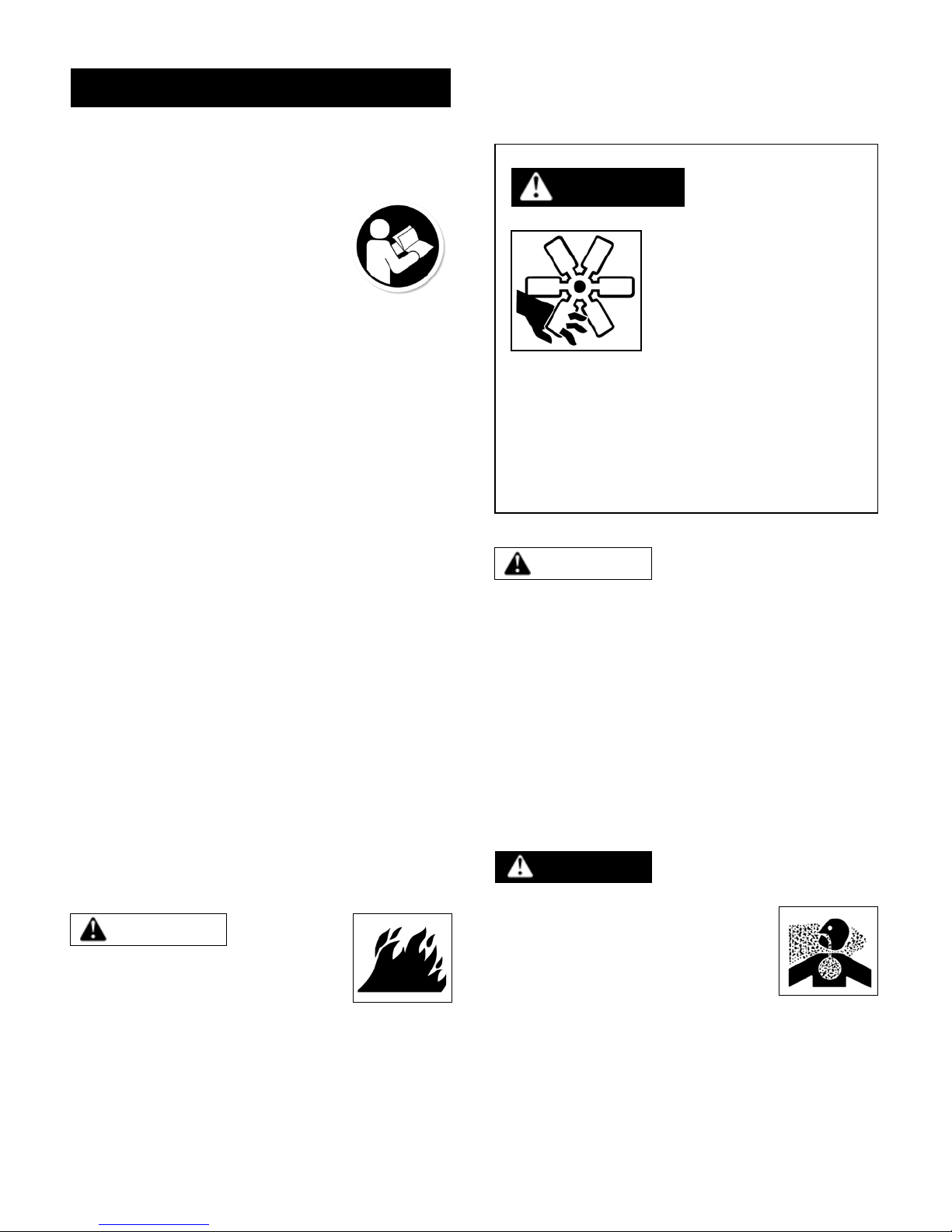
DANGER
A motionless atomizer may
appear safe, but its blade
could suddenly begin high-
speed rotation without
warning as a result of
control programming.
When the HRSM is automated by controls,
warning signs should be posted near the high-
speed equipment.
Disconnect and lock out power source to inspect
or service the unit.
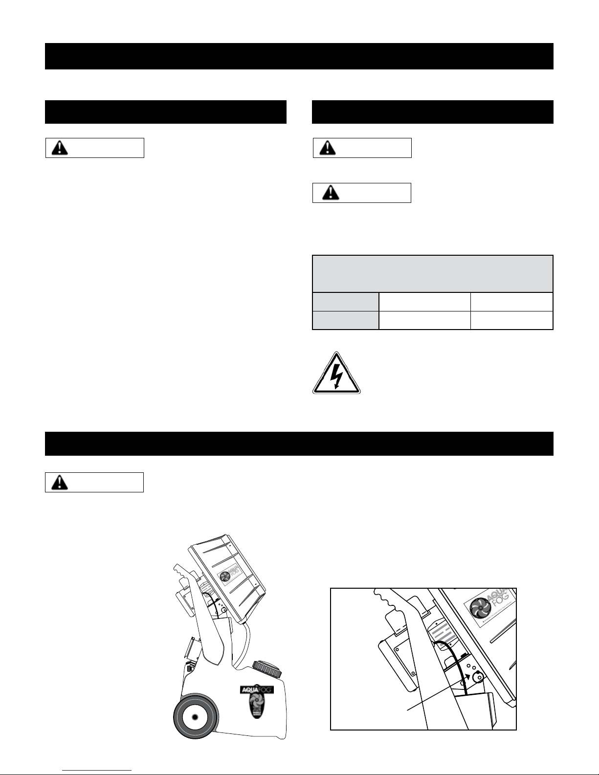
General Safety
Since the mobile HRSM uses high-speed
components to atomize liquids, the following safety
precautions must be observed at all times:
1. Read all manuals included
with this product. Be familiar
with the product and controls.
2. The HRSM is intended to be
used on level ground. Test for stability before
operation.
3. Follow United States Environmental Protection
Agency (EPA) guidelines and regulations when
fogging pesticide or chemical solutions.
4. Follow all local electrical and safety codes
as well as the United States National
Electrical Codes (NEC) and Occupational Safety
and Health Act (OSHA).
5. Only persons well acquainted with these rules
of safe operation should be allowed to use
the atomizer.
6. Keep visitors away and NEVER allow children in
the work area.
7. Use of an extension cord for the HRSM is
not recommended. If necessary, refer to the
A.W.G chart in the following section or
consult a certied electrician.
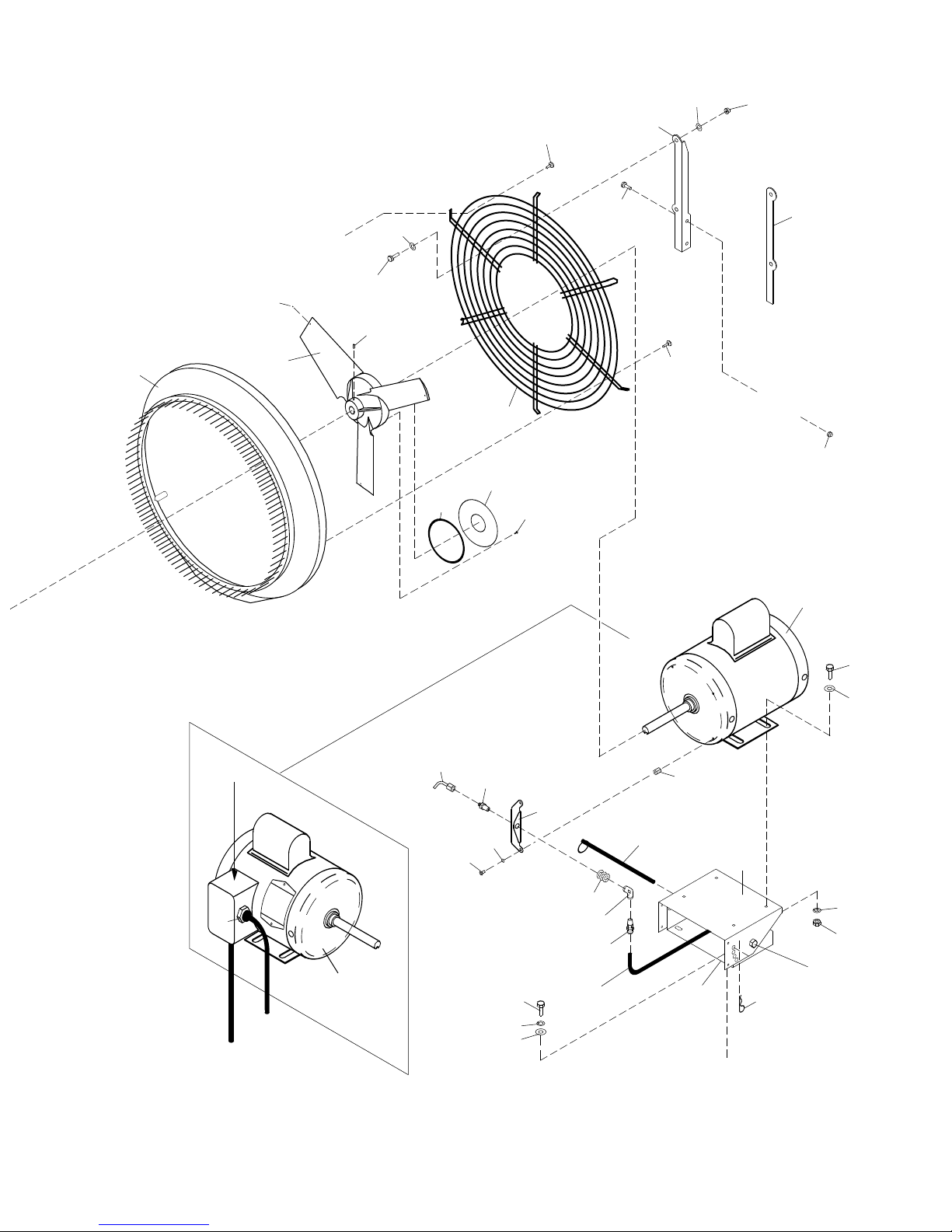
8. Before each use, inspect blade assembly
and electrical components for signs of damage,
deterioration, weakness or leakage. Repair or
replace defective items before using.
9. Check all fasteners at frequent intervals for
proper tightness.
MOTORS, ELECTRICAL EQUIPMENT AND
CONTROLS CAN CAUSE ELECTRICAL
ARCS THAT WILL IGNITE FLAMMABLE
LIQUID OR GAS. NEVER OPERATE
OR REPAIR IN OR NEAR FLAMMABLE LIQUID OR GAS.
NEVER STORE FLAMMABLE LIQUIDS OR GASES IN THE
VICINITY OF THE ATOMIZER.
DO NOT ATOMIZE
FLAMMABLE MATERIALS.
12. Humidity and cold air are
two common asthma triggers.
Asthmatic people working
with this equipment need to
be made aware of the risk.
13. When atomizing toxic chemicals, follow the
instructions provided by the chemical
manufacturer.
NEVER OPERATE HRSM
WITHOUT THE SAFETY GUARD
IN PLACE UNLESS THE UNIT IS RAISED SEVEN FEET
ABOVE WORKING HEIGHT.
WARNING
WARNING
DANGER
HIGH-SPEED ROTATION