Aquafog HYDRO SS 700 User manual

HYDRO SS 700
OPERATOR’S MANUAL
Read & Understand
Retain for Future Reference
NOTICE
►
DIRECT FEED

Notes
Purchase Date Model ID Number
Vendor Information

Read operator’s manual carefully and
thoroughly. Understand all safety warnings and instructions
before attempting operation of the unit.
Follow all local electrical and safety codes as well as the United
States National Electrical Codes (NEC) and Occupational Safety
and Health Act (OSHA).
Always operate SS 700 with it's safety guards and housing
securely in place.
Disconnect power before inspecting or servicing machine. Hydro
SS 700 must be properly grounded as a precaution against
possible electric shock. Check for correct voltage supply.
Keep cord away from heat, oil, sharp edges and moving parts.
Replace damaged cords immediately. Damaged cords increase
the risk of electric shock.
If use of an extension cord is necessary, use a heavy, gauge 3
wire extension cord with a molded three-prong plug.
Keep hands and all objects from entering the path of the blade.
Install the Hydro SS 700 at seven (7) foot height or higher for
added safety and optimum performance.
Do not use ammable liquids, caustic materials, or corrosive
materials with the Hydro SS 700.
When servicing Hydro SS 700, use only identical replacement
parts and follow instructions in the maintenance section of
this manual. Use of unauthorized parts or failure to follow
maintenance instructions may damage equipment or cause
personal injury.
GENERAL SAFETY
1.
2.
3.
4.
5.
6.
7.
8.
9.
10.
The Hydro SS 700 uses a high-speed
component to atomize water, the following
safety precautions must be observed at all
times:

When unpacking your unit, locate the following:
1) Hydro SS 700-DF
1) Flowmeter Assembly (20-300 cc/min)
12’) Drain Tubing
20’) 1/4” Water Tubing w/ Hose Connector
1) Operator’s Packet
1) Manual
1) U-Bolt Packet
5) Wire Ties
1) 1/4” Water Line Install Packet
1) Service Allen Wrench (for Blade Assembly)
THE HYDRO SS 700 CAN BE AUTOMATED WHEN USED IN CONJUNCTION
WITH A CONTROL. THE FAN MAY NOT APPEAR POWERED BUT COULD
SUDDENLY BEGIN HIGH-SPEED ROTATION AS A FUNCTION OF THE
PRESET CONTROL.
WARNING
HIGH-SPEED ROTATION, NEVER OPERATE UNIT WITHOUT THE HOUSING
AND SAFETY GUARDS INSTALLED.
UNPACKING
NOTIFICATION
GROUND FAULT RECEPTACLES ARE STRONGLY RECOMMENDED AND
MAY BE REQUIRED BY LAW.
NOTICE
WARNING

Where to Locate
NOTE: THIS UNIT IS SPECIFICALLY DESIGNED TO BE HUNG
Mount the fan high overhead in the largest available
open area. As a general rule, the higher the better
when mounting your fan. Allow one foot above the
unit and adequate room in front of and below the fan
for the unobstructed propulsion of the fog.
Mount the fan near the intake end of a ventilated
structure and propel fog in direction with air ow. In structures with no
ventilation, install the unit at the largest, most open end and propel the
fog towards the opposite end.
Utilize the pivoting fogging head in order to maximize the unit’s
performance.
DO NOT propel the fog into the wind or direction of airow.
DO NOT pivot the fogging head to propel fog at a sharp downward angle.
DO NOT cramp the fan in tight spaces or skinny aisleways.
DO NOT mount the fan near the ground or underneath tables or benches.
This would result in a high loss of fog onto the ground, though it
would not cause mechanical harm to the unit.
HANGING GUIDELINES
7'
OSHA regulations require
unprotected fan blades to be
mounted 7’ or higher from the
working surface.
AQUAFOG
HYDRO
SS

Small Structures
In applications requiring only
one unit, install the unit
anywhere along one end wall,
propelling the fog upward and
horizontally down the length of
the structure. If there is forced
ventilation, choose the intake
end of the structure. The best
location for automated controls
is behind the fan at an easily-
accessible level for monitoring.
Large Structures
Equally space the units within the structure. Lower humidity and/or cooling
requirements can allow for greater distance between fans. Usually, the
maximum distance between fans should be 20’ from the side and 35’ from
the front. If the structure has forced ventilation, shift the fans closer to the
intake end. The fans should always be propelling their fog with the direction
of natural or forced air ow.
Direction of air ow →
POSITIONING
Controller location area
Direction of air ow →
10’
20’
35’

Pull on tubing
Hose Connector
Push on retaining ring
Fig. 2
Hanging the Unit
After unpacking, locate or install a sturdy horizontal
support capable of handling over 20 pounds of
weight. If the support is a 3/4 - 1” pipe, use the
optional U-bolt packet provided. For the universal
mounting bolt attached, drill a 5/16” clearance hole
through the support where you want to hang the
unit. Using 1/2” wrenches, secure the (DF) unit into
position. See Fig. 1
Water Supply: DF units come equipped with a
20-300 cc/min. (.3 - 5 GPH) Flowmeter panel. This
panel should be mounted in an accessible location
for monitoring and adjusting water ow rate.
Cut 1/4” tubing at the desired location for the owmeter. Connect the
owmeter to the tubing between the Hydro unit and the water supply. Use the
remaining tubing and hose connector to connect to an available hose bib. To
remove hose connector, apply pressure to the retaining clip while pulling on
the tubing. See Fig. 2
INSTALLATION
or
With DF Control
No Control 115V
Receptacle
DF Control
“Piggyback”
Pre-wired Plug
Power Supply: Plug directly into a
properly grounded receptacle.
If using a DF Control, plug the Control into
the receptacle and then plug the fan into
the female side of the control’s pre-wired
plug. See Fig. 3
Fig. 1
Fig. 3

Lubricate Motor: Remove two blue plugs at the top
of the motor. Apply 4-5 drops of light grade petroleum
based oil at each bearing location 1 to 2 times a year
or as needed. Replace blue plugs. See Fig. 4
Cleaning Blade Assembly: After removing the blade
assembly, remove the stainless plate and O-ring. Soak
the blades in CLR for about one hour, scrub clean and
rinse off with water. Carefully check the small holes
leading into passageways that extend the
length of each blade. See Fig. 5 When
clean, test by blowing air through each
blade.
Water Solenoid:
Solenoids rarely
become clogged but
can be
disassembled and
cleaned if needed.
See Fig. 6
Clean Strainer: Periodically check and clean out debris
that gets caught in the in-line strainer.
Winterizing: Protect your unit from winter damage.
If storing unit in freezing temperatures, be sure all uid
is drained from the unit.
Fig. 5
Blade’s Reservoir Area
Water Passageway
O-ring
Stainless Face Plate
Blade
Assy.
Clip
Plunger
Water Solenoid from
optional control packages
Water Solenoid
Coil
Brass
Body
Screws
Fig. 6
3 in 1
oil
Oil ports
MAINTENANCE
Fig. 4
Fog Output
After the unit has been plugged
in and the water turned on, you
can adjust fogging output with the
owmeter’s ow control valve. Turn
counterclockwise to increase ow rate.
Pivot Feature
Pivot the fogging head anywhere
between 15° down and 40° up
from horizontal. The manufacturer’s
recommended angle is about 30° up.
OPERATION
Flow
Control
Valve
Flowmeter
Panel
Water
Supply In
Water Supply
Out
In Line
Strainer
Cap

INITIAL START-UP
1. Fan Blade Does Not Spin
2. No Fog but Blade Spins
3. Hard To See Fog Output
NO FOG
1. Stiff/Locked Motor Shaft
2. Bad Motor
3. Clogged Flowmeter Panel
4. Clogged In-Line Strainer
5. Clogged Water Solenoid
6. Clogged SST Feed Tube
POOR QUALITY FOG
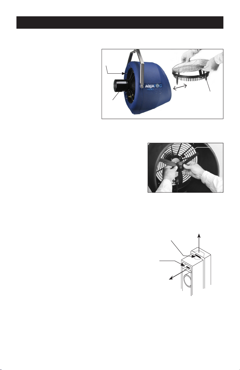
1. Clogged Blade Assembly
2. Misaligned Feed Tube
3. Stiff Motor Shaft
4. Loose Blade Assembly
FAN DOES NOT SPIN
1. Stiff/Locked Motor Shaft
2. Bad Motor
3. Bad Controller
MOTOR OVERHEATING
1. Stiff/Locked Motor Shaft
Issue
Corrective Action
TROUBLESHOOTING
1. Check power supply. If using a controller, try bypassing it and plug unit
directly into a power outlet. Check for a faulty power cord.
2. Open Flowmeter’s needle valve [counterclockwise]. Check for water
pressure starting at the source and temporarily disconnect water line
ttings to locate the issue. If using a controller and the water solenoid is
not opening, check the power from controller to solenoid.
3. As fog evaporates, it becomes transparent. Dry air and propulsion
evaporates fog quickly. As humidity increases, evaporation slows and fog
becomes more apparent. A dark background helps to see the output.
1. Remove blue plugs and lubricate motor bearings while manually rotating
shaft back and forth until loose.
2. If motor smells, doesn’t start (with a direct power supply) or shaft will not
loosen up, replace motor.
3. Remove valve and clean. If problem reoccurs, perform a thorough
cleaning inside the owmeter body.
4. Remove strainer cap, screen, and O-ring. Flush clean with water.
5. Remove the top clip and disassemble the valve’s brass body for cleaning.
6. Remove Feed Tube and ream with a small wire. Clean and reinstall.
1. Remove and clean out the rear reservoir and the blades’ passageways.
2. Adjust feed tube so its water stream ows into the blades rear reservoir.
3. Remove blue plugs and lubricate motor bearings while manually rotating
shaft back and forth until loose.
4. If the blade can spin without motor shaft, reposition the blade and tighten
the setscrew on the at of the shaft, replace assembly if necessary.
1. Remove blue plugs and lubricate motor bearings while manually rotating
shaft back and forth until loose.
2. If motor smells, doesn’t start (with a direct power supply) or shaft will not
loosen up, replace motor.
3. Check controller for loose connections, test unit’s motor and controller
independently with a direct power supply for process of elimination.
1. Remove blue plugs and lubricate motor bearings while manually rotating
shaft back and forth until loose.

Fan Blade Assembly
First remove the atomizing ring/front guard
assembly. The blade assembly is now
accessible and is secured to the motor shaft
with a setscrew. Loosen the setscrew using
1/16” Allen wrench (provided) and carefully
leverage blade assembly off the shaft.
See Fig. 8
To reinstall, line up setscrew with at of the
motor shaft and secure into position with
the blade assembly ush to the end of the
shaft.
Accessing The Motor
Disconnect the electrical power. After
removing the atomizing ring, front guard
assembly and blade assembly, use a 3/8”
nut driver or wrench to remove the four
10-32 nuts behind the blade assembly
securing the motor to rear guard.
See Fig. 8
Cleaning Flowmeter
Using a small at screwdriver, remove the
retaining key using Slot A by sliding the key
out toward the back. See Fig. 9 Next, use the screwdriver in Slot B to pull the
retainer cap straight up. After the retainer cap is removed, be careful not to
lose the internal oat ball when handling or cleaning the owmeter.
A
B
Screwdriver
Slot A
Screwdriver
Slot B
Top of Flowmeter
10-32
Nuts
SERVICE & REPAIR
Fig. 7
10-24
Flange Nuts
Motor
Atomizing Ring/Front
Guard Assy.
Atomizing Ring/Front
Guard Assembly
Using a 3/8” nut driver or
wrench, remove four 10-24
ange nuts located at the
back of the housing. To
remove and reinstall the
assembly, it needs to be
rotated horizontally in order
to clear the lip of the front
housing. See Fig. 7.
Fig. 8
Fig. 9

12
1
2
3
4
5
6
7
8
9
10 11
13
14
15
PART IDENTIFICATION
DESCRIPTION PART NO.
1 Atomizing Ring 400-001
2 Front Guard 400-002
3 Motor 115V 400-110
4 Rear Guard 400-127
5 Blade Assembly 400-128
6 Housing 400-100
7 SST Hanger a-620
8 Water Feed Tube 400-130
9 Pivot Location NA
10 Drain Barb Fitting 400-114
11 Drain Hose 400-089
12 Flowmeter Panel a-F-5
13 In-Line Strainer 71
14 1/4” Water Tubing W-14
15 Hose Connector W-2

Aquafog and accessories are warranted to the original purchaser
against defects in material and workmanship under normal use for one
full year from date of purchase. Any part determined to be defective and
returned to the manufacturer, shipping cost prepaid, will be repaired or
replaced at Jaybird Manufacturing, Inc.'s discretion without charge. Proof
of purchase date and an explanation of the problem or complaint must
accompany the returned portion of the machine.
Jaybird Manufacturing, Inc. reserves the right to verify the legiti-
macy of claimed defects. The provisions of this warranty do not apply to
damage resulting from direct or indirect misuse, negligence, accident,
lack of maintenance, or unauthorized repairs or alterations which affect
the machine's performance or reliability.
LIMITATIONS OF LIABILITY. TO THE EXTENT ALLOWABLE UNDER
APPLICABLE LAW, JAYBIRD MANUFACTURING, INC.'S LIABILITY FOR
DEATH, INJURIES TO PERSONS OR PROPERTY, OR FOR CONSEQUENTIAL
OR INCIDENTAL DAMAGES ARISING FROM THE USE OF OUR EQUIP-
MENT IS EXPRESSLY DISCLAIMED. JAYBIRD MANUFACTURING, INC.'S
LIABILITY IN ALL EVENTS IS LIMITED TO, AND SHALL NOT EXCEED,
THE PURCHASE PRICE PAID. NO OTHER WARRANTY, EXPRESSED OR
IMPLIED, IS AUTHORIZED, INCLUDING WARRANTIES OF MERCHANT-
ABILITY AND FITNESS FOR A PARTICULAR PURPOSE.
This warranty gives you specic legal rights, and you may also have other
rights, which vary from state to state.
1
year
ONE YEAR LIMITED WARRANTY
Made in U.S.A.
© 2020 Jaybird Mfg., Inc.
Jaybird Manufacturing, Inc.
135 Summer Lane
Centre Hall, PA 16828
Parts & Service: 1.814.364.1800
Website: www.jaybird-mfg.com
Other manuals for HYDRO SS 700
2
This manual suits for next models
1
Table of contents
Other Aquafog Electronic Cigarette manuals

Aquafog
Aquafog HRSM-2001 Manual

Aquafog
Aquafog GT 500-HS Manual

Aquafog
Aquafog XE 2000-HS Manual

Aquafog
Aquafog HRSM-2000 Manual

Aquafog
Aquafog XE CRSM User manual

Aquafog
Aquafog XE-ORSM-1000 Manual

Aquafog
Aquafog Turbo XE Manual

Aquafog
Aquafog XE ORSM Manual

Aquafog
Aquafog XE HRSM Manual

Aquafog
Aquafog XE-HRSM-2000-EXP Manual