3
11. If the equipment starts to vibrate abnormally,
STOP the motor and check immediately for
the cause. Vibration is generally an indication
of trouble.
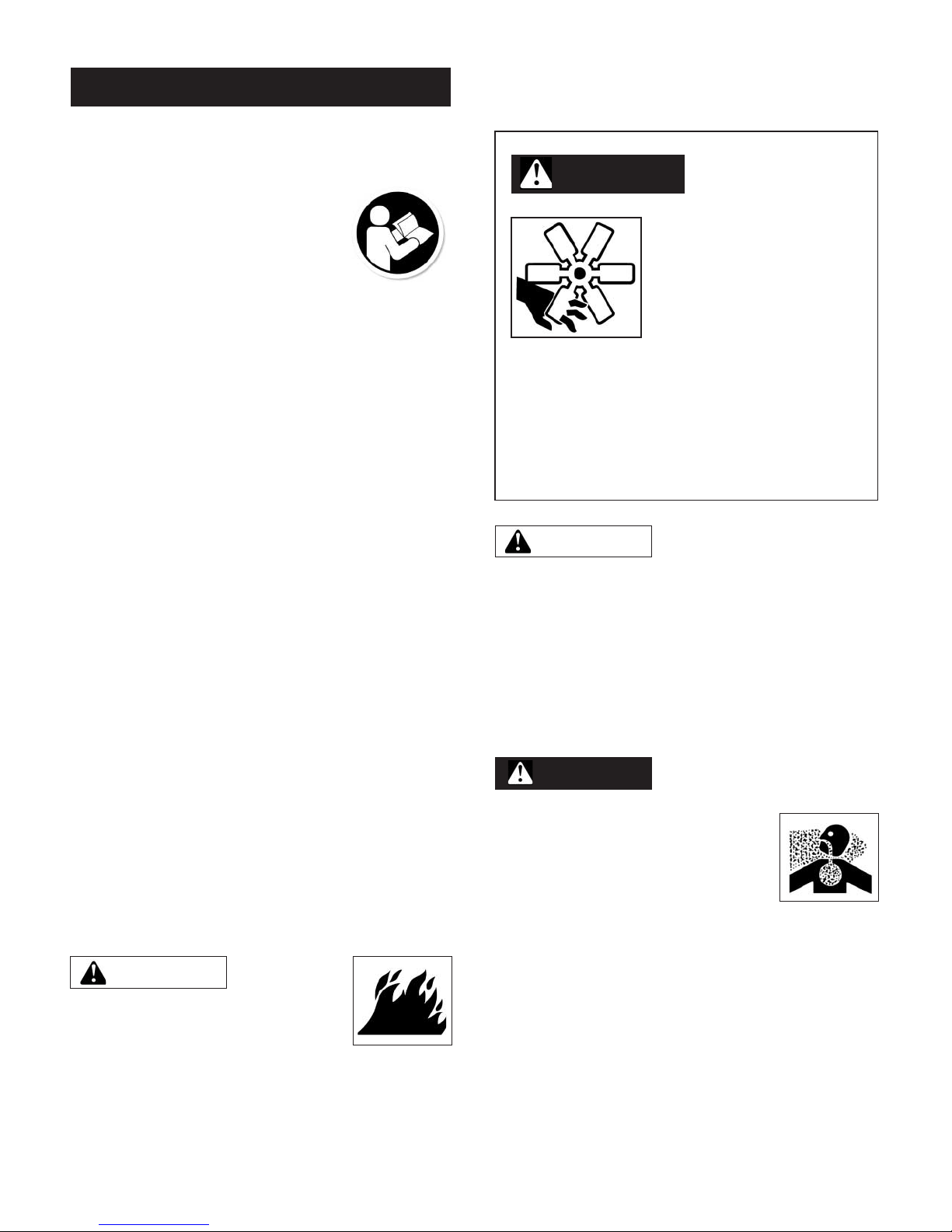
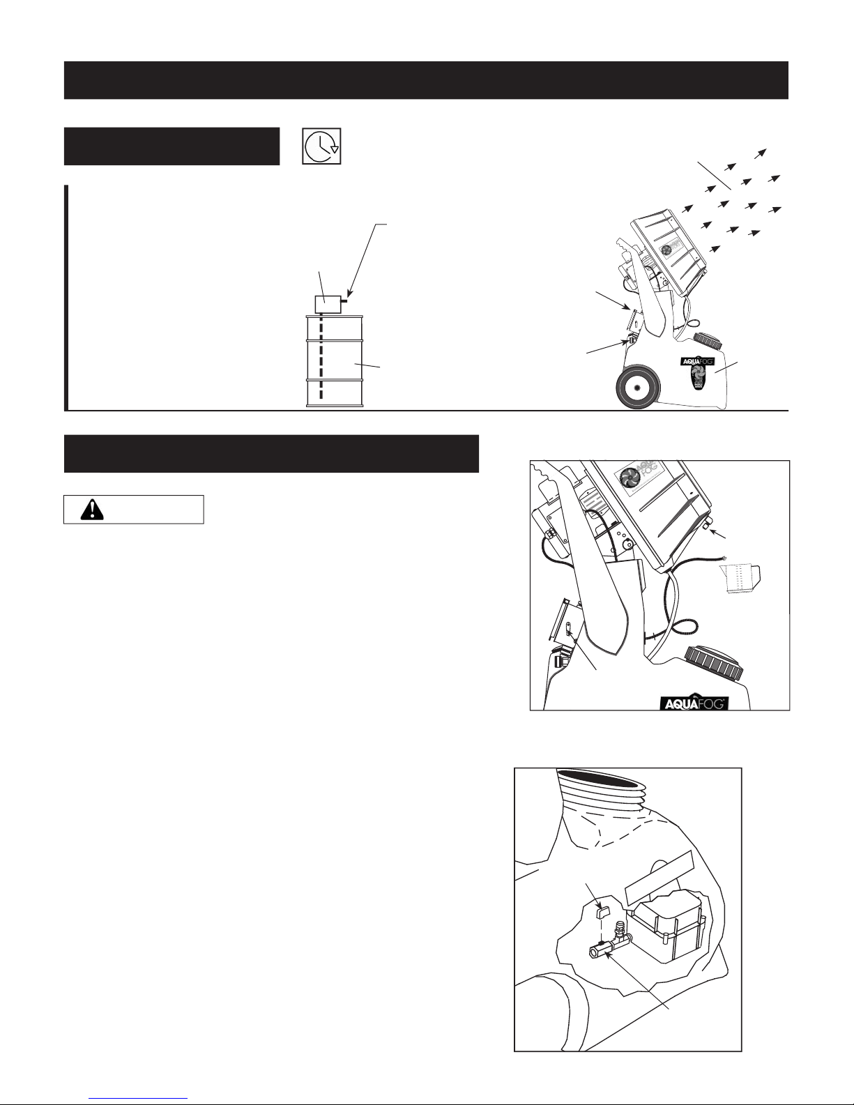
Fogging Precautions
DANGER
A motionless atomizer may
appear safe, but its blade
could suddenly begin high-
speed rotation without
warning as a result of
control programming.
When the ORSM is automated by controls,
warning signs should be posted near the high-
speed equipment.
Disconnect and lock out power source to inspect
or service the unit.
GENERAL SAFETY
Since the mobile ORSM uses high-speed
components to atomize liquids, the following safety
precautions must be observed at all times:
1. Read all manuals included
with this product. Be familiar
with the product and controls.
2. The ORSM is intended to be
used on level ground. Test for stability before
operation.
3. Follow United States Environmental Protection
Agency (EPA) guidelines and regulations when
fogging chemical solutions.
4. Follow all local electrical and safety codes
as well as the United States National
Electrical Codes (NEC) and Occupational Safety
and Health Act (OSHA).
5. Only persons well acquainted with these
rules of safe operation should be allowed to
use the atomizer.
6. Keep visitors away and NEVER allow children in
the work area.
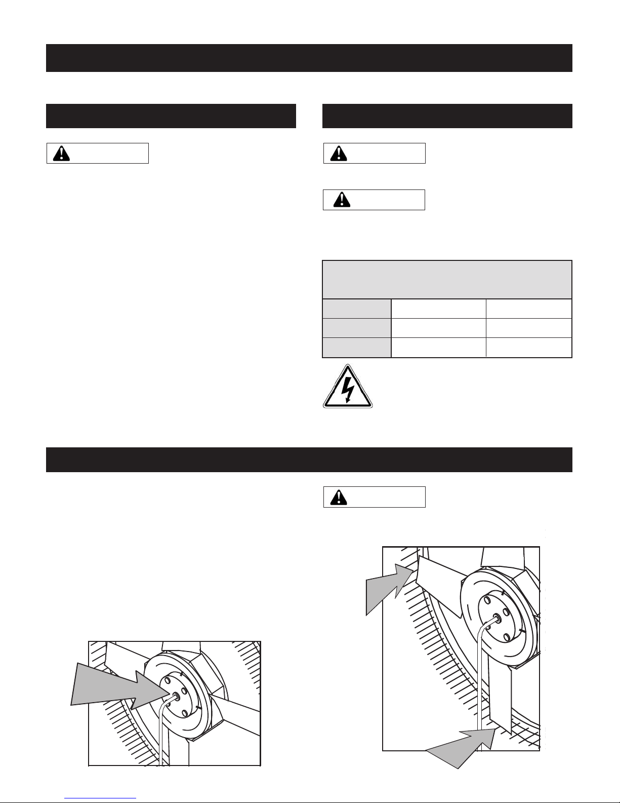
7. Use of an extension cord for the ORSM is
not recommended. If necessary, refer to
the A.W.G chart in the following section or
consult a certied electrician.
8. Before each use, inspect blade assembly
and electrical components for signs of damage,
deterioration, weakness or leakage. Repair or
replace defective items before using.
9. Check all fasteners at frequent intervals for
proper tightness.
10. Keep ngers away from a running unit;
fast moving and hot parts will cause injury
and/or burns.
MOTORS, ELECTRICAL EQUIPMENT AND
CONTROLS CAN CAUSE ELECTRICAL
ARCS THAT WILL IGNITE FLAMMABLE
LIQUID OR GAS. NEVER OPERATE OR
REPAIR IN OR NEAR FLAMMABLE LIQUID OR GAS.
NEVER STORE FLAMMABLE LIQUIDS OR GASES IN THE
VICINITY OF THE ATOMIZER.
POTENTIALLY HAZARDOUS
CHEMICAL VAPORS
12. Avoid exposure to
hazardous chemicals. Wear a
respirator and protective
clothing - goggles, gloves, long
sleeves and pants, etc.
13. Read and understand all directions and safety
precautions before operating ORSM. Follow all
E.P.A. guidelines for chemical use.
14. NO humans or animals should be in the area
during chemical/pesticide application.
SERIOUS INJURY OR DEATH COULD OCCUR!
15. Follow chemical manufacturer's
instructions regarding length of restricted
entry interval (REI).
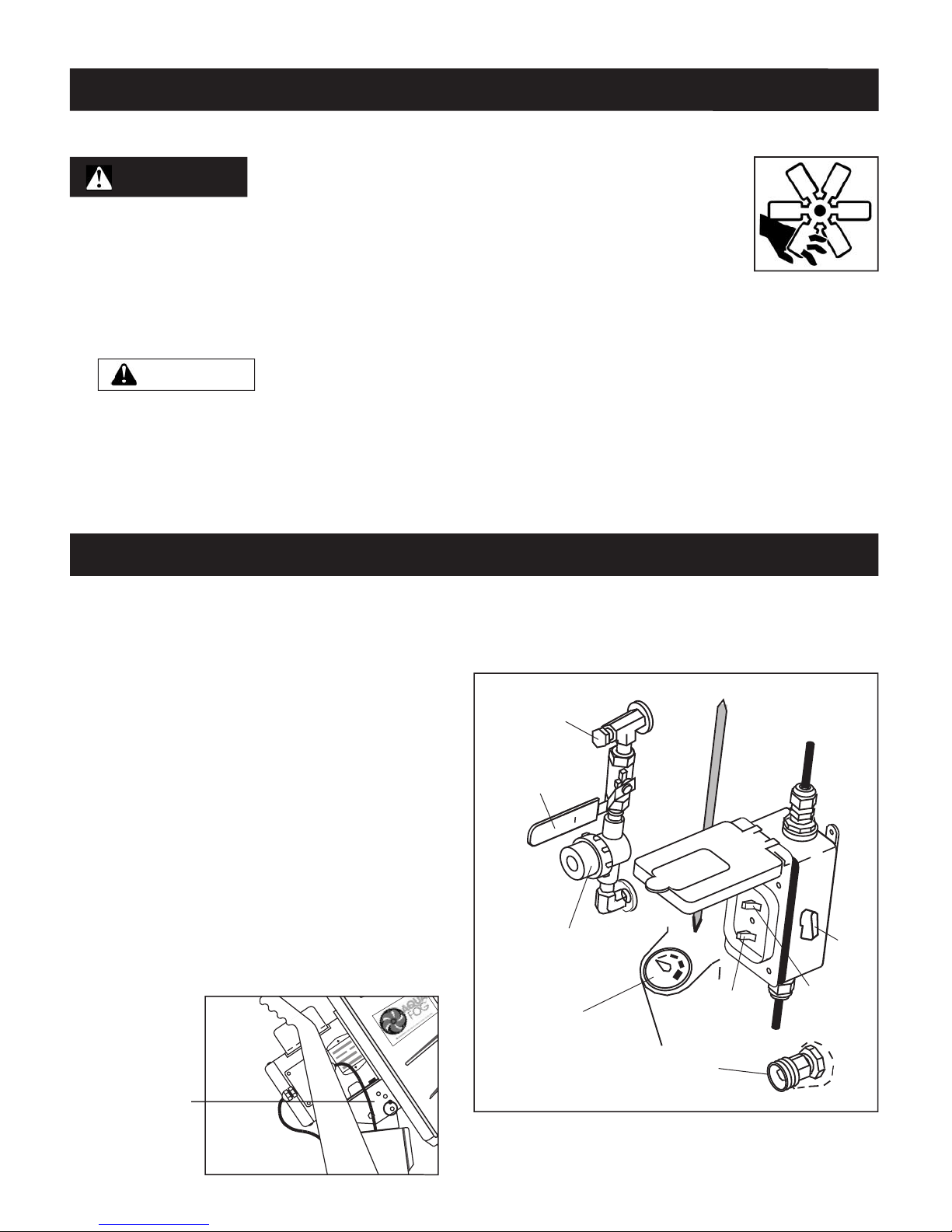
NEVER OPERATE ORSM
WITHOUT THE SAFETY GUARD
IN PLACE UNLESS THE UNIT IS RAISED SEVEN FEET
ABOVE WORKING HEIGHT.
WARNING
WARNING
DANGER
HIGH-SPEED ROTATION