Aquafog HRSM-2001 Manual

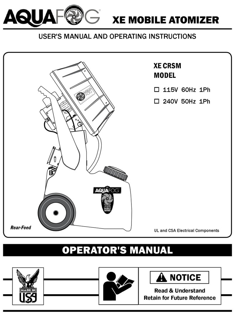
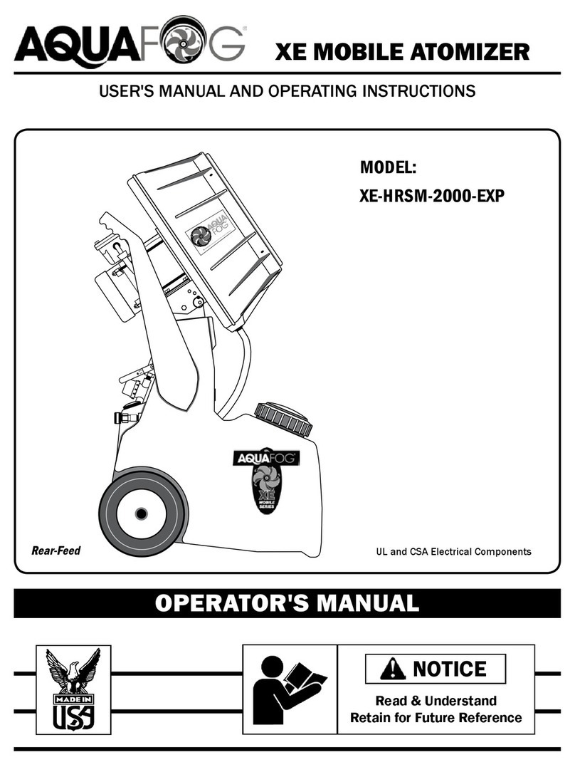
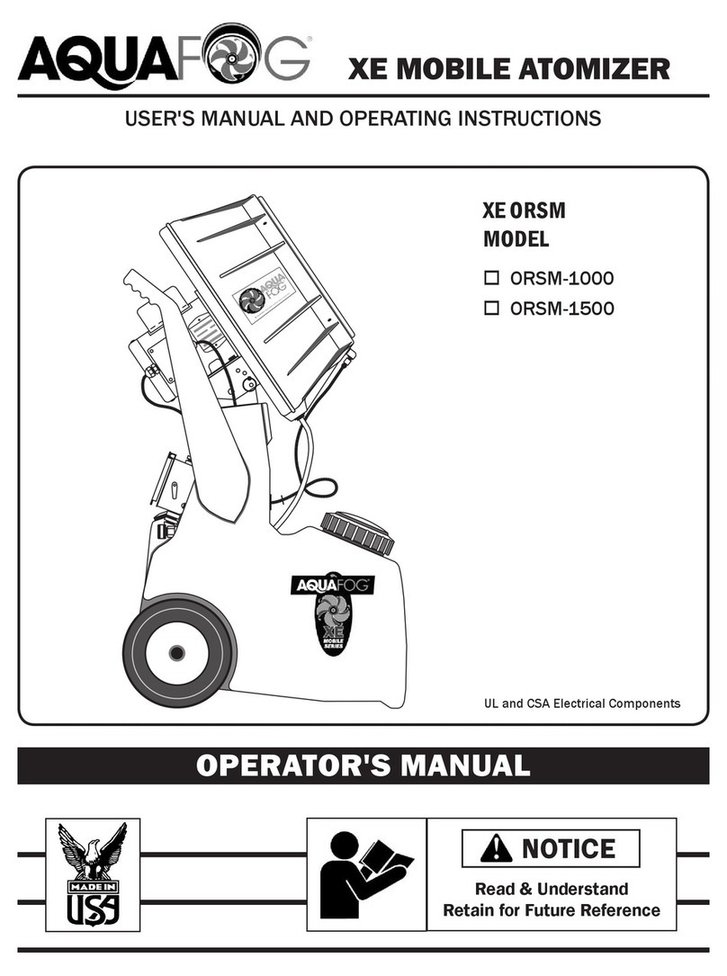
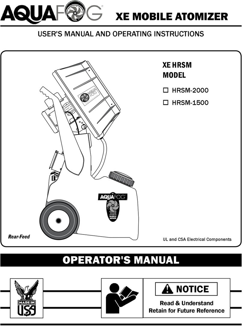
XE HRSM
MODEL
o HRSM-2000
o HRSM-2001 (3ph)
o HRSM-1500
Read & Understand
Retain for Future Reference
XE MOBILE ATOMIZER
USER'S MANUAL AND OPERATING INSTRUCTIONS
OPERATOR'S MANUAL
UL and CSA Electrical Components
NOTICE

General Safety . . . . . . . . . . . . . . . . . . . . . . . .
Getting Started . . . . . . . . . . . . . . . . . . . . . . . .
Controls and Installation . . . . . . . . . . . . . . .
Evaluation and Schematics . . . . . . . . . . . . .
Troubleshooting . . . . . . . . . . . . . . . . . . . .
Aquafog Fan Exploded View . . . . . . . . .
HRSM Tank Exploded View . . . . . . . . . .
Maintenance . . . . . . . . . . . . . . . . . . . . . . . . .
Warranty . . . . . . . . . . . . . . . . . . . . . . . . . . . .
2
PAGE
3
4
5
6
7 - 8
9 - 10
11 - 12
13
14
SAFETY GUIDELINES
This manual contains very important information.
This information will help ensure SAFETY and
PREVENT EQUIPMENT PROBLEMS. Use these
symbols to understand safety guidelines.
DANGER DANGER INDICATES AN
IMMINENTLY HAZARDOUS
SITUATION WHICH, IF NOT AVOIDED, WILL RESULT IN
DEATH OR SERIOUS INJURY.
WARNING INDICATES A
POTENTIALLY HAZARDOUS
SITUATION WHICH, IF NOT AVOIDED, COULD RESULT IN
DEATH OR SERIOUS INJURY.
CAUTION INDICATES A
POTENTIALLY HAZARDOUS
SITUATION WHICH, IF NOT AVOIDED, MAY RESULT IN
MINOR OR MODERATE INJURY.
NOTICE INDICATES IMPORTANT
INFORMATION, THAT IF NOT
FOLLOWED, MAY CAUSE DAMAGE TO EQUIPMENT.
TABLE OF CONTENTS
WARNING
CAUTION
NOTICE
Notes
DESCRIPTION
Aquafog mobile units are intended to condition large
volumes of air using water or other non-hazardous
liquids at air temperatures between 31ºF and 145ºF.
Any other use of these units will void the warranty
and the manufacturer will not be responsible for
problems or damages resulting from misuse.

3
10. Keep ngers away from a running unit;
fast moving and hot parts will cause injury
and/or burns.
11. If the equipment starts to vibrate abnormally,
STOP the motor and check immediately for
the cause. Vibration is generally an indication
of trouble.
Fogging Precautions
DANGER
A motionless atomizer may
appear safe, but its blade
could suddenly begin high-
speed rotation without
warning as a result of
control programming.
When the HRSM is automated by controls,
warning signs should be posted near the high-
speed equipment.
Disconnect and lock out power source to inspect
or service the unit.
GENERAL SAFETY
Since the mobile HRSM uses high-speed
components to atomize liquids, the following safety
precautions must be observed at all times:
1. Read all manuals included
with this product. Be familiar
with the product and controls.
2. The HRSM is intended to be
used on level ground. Test for stability before
operation.
3. Follow United States Environmental Protection
Agency (EPA) guidelines and regulations when
fogging pesticide or chemical solutions.
4. Follow all local electrical and safety codes
as well as the United States National
Electrical Codes (NEC) and Occupational Safety
and Health Act (OSHA).
5. Only persons well acquainted with these
rules of safe operation should be allowed to
use the atomizer.
6. Keep visitors away and NEVER allow children in
the work area.
7. Use of an extension cord for the HRSM is
not recommended. If necessary, refer to
the A.W.G chart in the following section or
consult a certied electrician.
8. Before each use, inspect blade assembly
and electrical components for signs of damage,
deterioration, weakness or leakage. Repair or
replace defective items before using.
9. Check all fasteners at frequent intervals for
proper tightness.
MOTORS, ELECTRICAL EQUIPMENT AND
CONTROLS CAN CAUSE ELECTRICAL
ARCS THAT WILL IGNITE FLAMMABLE
LIQUID OR GAS. NEVER OPERATE OR
REPAIR IN OR NEAR FLAMMABLE LIQUID OR GAS.
NEVER STORE FLAMMABLE LIQUIDS OR GASES IN THE
VICINITY OF THE ATOMIZER.
DO NOT ATOMIZE
FLAMMABLE MATERIALS.
12. Humidity and cold air are
two common asthma triggers.
Asthmatic people working
with this equipment need to
be made aware of the risk.
13. When atomizing toxic chemicals, follow the
instructions provided by the chemical
manufacturer.
NEVER OPERATE HRSM
WITHOUT THE SAFETY GUARD
IN PLACE UNLESS THE UNIT IS RAISED SEVEN FEET
ABOVE WORKING HEIGHT.
WARNING
WARNING
DANGER
HIGH-SPEED ROTATION
Un-crate carefully and position HRSM on
level ground.
Save crate and packing materials until
evaluation and testing are complete.
Read manual carefully and understand all
instructions.
Do not connect power until after thorough
inspection and lling the sump with liquid.
After lling the unit with some liquid, inspect
for leaks.
Never operate without liquid in tank.
Be sure guards are securely in place and
warnings are clearly visible.
Check power supply for correct voltage.
4
GETTING STARTED
UNPACKING CHECKLIST
DO NOT OPERATE UNIT IF
DAMAGED DURING SHIPPING,
HANDLING OR USE. DAMAGE MAY RESULT IN BREAKAGE
AND CAUSE INJURY OR PROPERTY DAMAGE.
WARNING
Fig. 1
Fig. 2
EXTENSION CORD SPECIFICATIONS*
FOR SINGLE FAN USE ONLY • (AWG - American Wire Gauge)
Voltage 25 to 50 ft. 50 to 100 ft.
115 14 AWG 12 AWG
230 16 AWG 14 AWG
Fig. 12
ELECTRICAL
GROUND FAULT RECEPTACLES
ARE RECOMMENDED AND MAY
BE REQUIRED BY LOCAL AND/OR NATIONAL CODE.
WARNING
USE OF AN EXTENSION CORD IS
NOT RECOMMENDED.
IF NECESSARY, REFER TO FIG. 12.
NOTICE
*Grounded and suitable for outdoor use.
UNIT PREPARATION
Visually check to make sure that the critically
important liquid feed tube (Part #6) has maintained
its center position, partially inserted into the blade
assembly. Re-position if necessary. (See Fig. 1)
Visually check to make sure the blades can rotate
freely without touching any venturi pins. There should
be approximately 1/4" space between the pins and
the blades. (See Fig. 2) Do Not operate if blades may
hit pins. Refer to troubleshooting for adjustments.
ENSURE THE BLADE ASSEMBLY
IS CENTERED INSIDE THE
PINNED VENTURI. ADJUST MOTOR AND BLADE AS
NECESSARY.
WARNING

5
Fig. 3
Flow Control
Valve
In-Line
Strainer
Fluid Level
Gauge
Hose
Connection
CONTROLS/ FEATURES
The volume of fog can be regulated by adjusting the
Flow Control Valve. (See Fig. 3)
Particle size is smaller at lower outputs, so it is
better to operate the unit at a lower output for longer
periods of time.
At the base of the plumbing is an in-line strainer with
a removable cap. Periodically check inside and ush
any sediment from the screen. (See Fig. 3)
The HRSM is equipped with a four position pivoting
fogging head with 15º intervals up to 45º.
Propelling the fog upward allows more time for the
particles to evaporate, keeping oor areas drier.
When making an adjustment, balance the weight of
the fogging head off of the pin for easy removal.
(See Fig. 4)
Flow Control /Strainer /Pivot
Fig. 4
Adjustment Pin
►
▼
▲
OFF
ON
INSTALLATION
A) Automated Operation
Connect the unit's power cord to a
power supply controller and switch
on the unit's toggle switch.
B) Manual Operation
Plug unit into an available dedicated
20A power supply and use the
unit's On/Off toggle switch to control
operation.
SETUPS
Power
On/Off
►
Automated Power
Supply Controler
Liquid Supply
Hose Connection
Liquid
Storage
Atomized
Liquid
20A Dedicated
Power Supply ►
On/Off
Toggle

mtr
240V
mtr
240V
N
mtr
FAN
PUMP
SPST
TGS
FAN
mtr
TPST
TGS
TPST
TGS
PHASE PHASE
PHASE
PUMP
FAN
PUMP
TPST
TGS
N
240 VAC
LINE
115 VAC
LINE
mtr
DPST
TGS
DPST
TGS
115V 1PH 60/50 HZ
Domestic (USA)/ Foreign
ELECTRICAL SCHEMATICS
Note: All green wires
go to ground
Denotes Line Connection
Denotes Termination
On
2, 4, 5 1, 3, 8
Brown Blue
Off
115V On
2, 3, 8
4, 5
Brown Blue
Off
240V 1 PH 50 HZ
Foreign
208-230V 3PH 60HZ
Domestic (USA)
1
On
Off
On
2, 3, 8
3, 9
Brown
Green
Off
208-230V
115V
1, 7
On
Off
Blue &
On
Off 2, 8
6
mtr
115V
TESTING AND EVALUATION
► Turn on the unit and listen for any possible abnormalities, such as the blades rubbing against the
venturi. Make re-adjustments if necessary.
► Evaluate fog quality adjusting the output by using the ow control valve. (See Fig. 3). After starting, it
generally takes several seconds for the liquid to reach the atomizing fan.
BEFORE TESTING FAN MAKE SURE ALL OBJECTS ARE OUT OF THE
ROTATION PATH OF THE FAN BLADES.HIGH-SPEED WARNING. KEEP HANDS
CLEAR! MAKE SURE GUARDS ARE INSTALLED OR UNIT IS OUT OF REACH.
DANGER
CAREFULLY LISTEN FOR UNUSUAL NOISE OR VIBRATION.
CAUTION
► For rst-time evaluation, ll tank (with water only) about one quarter full.
► Connect to power supply.
► BUMP START HRSM and check for proper fan blade rotation (clockwise if looking at front of unit).
If incorrect, nd rotation connection changes on the motor's electrical schematic.

7
1. Fan Does Not Operate
A.) Check voltage requirements on unit and electrical supply. Check for live receptacle, plug,
power line and toggle switch.
B.) Look for any loose connections inside the main motor's junction box.
2. Blades Rub Against Venturi
A.) To make a horizontal adjustment, loosen the 4 bolts (Part #56) at the base of the main
fan motor and shift motor side to side until centered. Retighten bolts.
B.) To make a vertical adjustment, slightly loosen 4 bolts (Part #117) and make necessary
adjustments. Retighten bolts.
3. Unusual Noise
A.) It is normal to hear a slight rattling noise at start-up and shut-down. This is caused by the
tip of the liquid feed tube entering the center of the fan blade assembly reservoir.
B.) Squealing at start-up or during operation may be caused by the motor shaft's bearing
seal. Spray with lubricant at the front of the motor where the shaft exits the motor's
frame.
4. No Fog
A.) Check to see if ow control valve is open. The valve is open when the handle is down
and closed when up. If the valve is open and there is still no fog, the pump may need
to be primed. In rare cases the pump may retain an air bubble. To prime the pump,
remove the inline strainer cap (Part #71) and turn the system ON for a few seconds.
Replace cap and try operating unit again.
B.) If pump is receiving electricity but there is no fog, check for sediment in the pump's intake
screen. Spray around the pump with a garden hose or remove the pump and thoroughly
clean the intake screen. Clean and ush out the tank area by removing the drainage plug
located on the bottom rear of RSM.
C.) If no liquid enters the tank when using the automatic ll, check oat valve assembly for
debris. When the oat arm is up, water should shut off; when it is down, water should
freely enter RSM tank.
5. Liquid Spilling From Overow Port
A.) Check the oat valve assembly. If the oat (Part #99) is lling with water, it should be
replaced. Also check to see if debris is not allowing the valve (Part #97) to seal properly.
Clean as needed.
B.) Reduce the in-line water pressure.
TROUBLESHOOTING
BEFORE INSPECTION AND /OR SERVICE
DISCONNECT AND LOCK OUT POWER SOURCE.
WARNING

8
Contact Your Sales Representative for Further Assistance.
6. Poor Quality Fog
A.) The liquid feed tube (Part #6) may not be inserted properly into the reservoir. The feed
tube must be inserted approximately 1/4" into the center bearing, but it should not touch
the back of the reservoir.
B.) Reservoir may be clogged. Fluid entering a clogged reservoir will spill out of the center
bearing instead of entering the passageways of the fan blades. To clean, remove the
blade assembly from the motor shaft and totally disassemble. Next, ush the reservoir
under a sink, making sure the passageways are cleared. Check and clear the
passageways of each individual blade as well. Reassemble and reattach.
7. Fan Motor Becomes Excessively Hot
The main fan motor normally becomes very hot to the touch. However, if it gets so hot that it
begins to smell or smoke or the power cord becomes hot, discontinue operation and consult
an electrician to properly evaluate the problem.
8. Electrical Breaker Tripping
If the electrical breaker trips off, there is an overload in the system and there may be a serious
motor problem. Turn off all other devices connected to the same circuit. If the breaker continues
to trip, the motor is probably in need of repair. Consult an electrician for evaluation.
9. Fan and/or Motor Vibration
A.) If the fan unit begins vibrating severely, rst be sure the blade assembly is fully engaged
and securely tightened on the motor shaft. Next, inspect the blade assembly, particularly
the ends of the blades. Look for wear or cracks - replace as necessary. Look for deposits
of calcium or minerals - clean and remove mineral deposits and/or calcium.
B.) If the vibration seems to be coming from the motor, rst check that the motor mounting
hardware is securely tightened. If hardware is secure, remove the blade assembly and
operate the motor without the blade. If vibration continues, the motor has a serious
mechanical problem and probably needs to be replaced.
10. Liquid Spilling From Fan Housing
If liquid builds up inside the housing, the drain tube is probably clogged. Clean debris
from the drain strainer and drain tube.
11. Plumbing Leaks
Un-thread ttings and clean both the male and female threads. Apply new thread tape
(approximately 2-3 wraps) and reconnect. If a tube tting is leaking, tighten the cap - no
more than 1 turn past nger tightened. If the leak persists, replace the tube tting insert.
TROUBLESHOOTING (CONT.)
BEFORE INSPECTION AND /OR SERVICE
DISCONNECT AND LOCK OUT POWER SOURCE.
WARNING

AQUA
FOG
9
288 294
#15 Fan Blade Assembly Explosion
1
7
6
17
19
27
32
30
33
29
28
31
34
41
35
35
114
115
435
42
417
427
AQUAFOG FAN EXPLODED VIEW
1 Housing 1
2 Safety guard 1
6 SST feed tube 1
7 Liquid feed tube tting 1
8 Drain tting 2
13 Fan motor (specify Phase) 1
14 Pinned venturi assembly 1
15 Fan blade assembly (1 HP, 30°) 1
16 Rear guard 1
17 Fan blade (1 HP, 30°) 4
19 SST Face plate & bearing 1
20 1/4" Heavy large diameter washer 8
27 Blade spacer 4
28 Reservoir (4 hole) 1
29 Front hub 1
30 Rear hub 1
31 1/4-20 x 1 1/4" HH bolt SST 4
32 1/4-20 nylon stop nut SST 12
33 1/4-20 x 3/8" socket set screw SST 2
34 Blade feeder tube 4
35 SST washer for feed tube tting 2
39 Drain strainer 1
41 10-24 x 1/2" phillips RH SST 4
42 10-24 nylon stop nut SST 4
43 11/16 x 1 1/4" at washer SST 1
44 Drain tubing 3'
45 Liquid-tight cord tting 2
46 Key 1
52 1/4-20 x 3/4" HH bolt SST 4
54 1/4-20 x 3/8" button head cap screw 6
56 5/16-18 x 3/4" HH bolt SST 8
57 5/16" lock washer SST 8
58 5/16" at washer SST 12
114 Drain tting nut 1
115 Drain gasket 1
116 5/16-18 nish nut SST 4
117 1/4-20 x 5/8" HH bolt SST 4
288 1/8" NPT-F elbow 1
294 1/8" NPT-M x 3/8" tube tting 1
340 3/8" black tubing clamp 1
349 5/16" brass rod 1
391 Top pivot plate 1
392 Bottom pivot plate 1
394 Brass pivot washer 2
395 5/16" nylon lock nut 2
403 Brass ring 2
405 3/8" x 1 1/4" fender washer SST 1
417 Machine Nut 4
427 Safety Guard Clip 4
435 Reservoir O-ring 1
479 Hair pin SST 1
600-L RSM support left 1
600-R RSM support right 1
W-38 3/8" tubing 5'
ID # Description Qty/Unit
PART IDENTIFICATION
405
340
W-38

10
1/2 HP
TURBO
Top of RSM
Side view of motor
Side of top
pivot plate
Rear of
Housing
Power supply in-
from on/off switch
Power supply out-
to pump
8
13
14
15
16
52
600-L
117
54
20
344
46
58
56
45
45
43
8
39
44
32
58
57
56
57
116
349
403 391
392
56
394
395
32
479
20
600-R

11
XE
MOBILE
SERIES
AQUAFOG
Jaybird Mfg., Inc.
65
59
372
76
82
85
86
86
92
89
88
87
351
60 61
84
109
45
110
71
69
75
72
72
65
65
143
143
65
65
84
45
198
67
65
Tank's Wall
Inside Tank
93
94
96
677
Three Phase Components
Single Phase Components
HRSM TANK EXPLODED VIEW
487
SJO-14/4
281
Wall

H
12
PART IDENTIFICATION LIST
Internal tank pump components
65
65
67
372
97
99
443
606
108
297
98
55
100
101
32
154
126
111
Inside Tank
Inside Tank
ID # Description Qty/Unit
PART IDENTIFICATION
32 1/4-20 nylon stop nut SST 2
45 Liquid-tight cord tting 2
55 M20 Serrated lock washer SST 1
59 Fluid level gauge 1
60 RSM tank 1
61 Fill cap 1
65 1/2" at washer SST 8
67 5/32 x 1 1/4" cotter pin SST 2
69 1/4" NPT close nipple 1
71 Inline strainer 1/4" female NPT 1
72 1/4" NPT street elbow 2
75 Flow control valve 1
76 10-24 x 3/4" phillips RH SST 2
82 Electrical switch box 1
84 3/4" M socket x 1/2" F NPT Bushing 2
85 Switch cover 1
86 6-32 x 1/2" oval slotted screw 6
87 Electrical switch box (3 phase) 1
88 Switch (3 phase) 1
89 Spacer plate (3 phase) 1
92 Switch cover (3 phase) 1
93 Hose connector gasket 1
94 Hose connector 1
96 Gasket 1
97 Float valve 1
98 Stem 1
99 Float 1
100 Pump HRSM 115 volt 60hz. 1
101 Pump HRSM 230 volt 50hz. 1
108 #8 x 3/8" self tapping phillips SST 2
109 Switch 115 volt 1
110 Switch 230 volt 1
111 Axle SST 1
126 1/4" lock washer SST 2
143 1/4" NPT-M x 3/8 tube tting 2
154 1/4-20 nish nut SST 2
198 18' power cord and plug 115V 1
281 10-24 keps nut SST 2
288 1/8" NPT elbow 1
294 1/8" NPT-F x 3/8 tube tting 1
297 1/4" NPT-F x 3/8 tube tting 1
344 10-24 x 1/2" phillips truss head SST 4
351 1" NPT black nylong hex plug 1
372 Heavy-duty RSM wheel 2
443 1/4-20 x 1-1/4" HH bolt 2
487 3Ph Pulg 208-230V 1
606 H Pump support bracket 1
677 11/16 x 1-1/4" at washer SST 1
SJO-14/4 4 wire 14 guage (3Ph power cord) 18'

13
MAINTENANCE
1. Clean Strainers
The RSM is equipped with 3 strainers that should be cleaned periodically - the Drain
Strainer (Part #39) in the Tank, the Inline Strainer (Part #71) at the bottom of the
Flow Control Valve and the Pump Screen on the Pump. Check strainers and remove
any trapped debris.
2. Flush Out Tank
The tank should be rinsed regularly, especially if using chemicals. Remove drain plug
(Part #351) and, using a garden hose, thoroughly ush tank and pump of any sediment.
3. Lubricate Main Motor
The main motor is a permanently lubricated motor, but it is benecial to apply spray oil
around the shaft where it exits the motor body. Lubricate motor once a season or
whenever squealing occurs.
4. Inspect Blade Assembly
Clean the blade assembly about once a year, especially if a lm of calcium or mineral
deposits is visible on the exterior of the blades. Remove any build-up from the blades
and any debris from blade passageways. While cleaning, inspect for irregularities or
hairline cracks and replace as necessary.
5. Storage
Protect your mobile Aquafog from winter damage. Expansion due to freezing can burst
the ttings or the internal feed pump. If storing unit in below freezing temperatures,
be sure all uid is drained from the tank area. Damage due to freezing is not covered
under warranty.
DISCONNECT AND LOCK OUT POWER SOURCE
BEFORE SERVICING
WARNING

This manual suits for next models
2
Table of contents
Other Aquafog Electronic Cigarette manuals

Aquafog
Aquafog XE CRSM User manual

Aquafog
Aquafog XE ORSM Manual

Aquafog
Aquafog Turbo XE Manual

Aquafog
Aquafog HYDRO SS 700 User manual

Aquafog
Aquafog XE-ORSM-1000 Manual

Aquafog
Aquafog XE-HRSM-2000-EXP Manual

Aquafog
Aquafog Turbo XE Manual

Aquafog
Aquafog GT-500 Manual

Aquafog
Aquafog XE 2000-HS Manual

Aquafog
Aquafog HRSM-2000 Manual