ARB 17940080 User manual
Last Rev Date: 21/09/2022
Page 1 of 19
Fitting instructions# 37801108
Copyright © 2022 by ARB Corporation Limited. All rights reserved; this document must not be reproduced without the express authority of ARB Corporation Ltd
Part Number(s):
Suits BASE RACK:
17940080
1770060/70
Product Description:
BASE RACK fitting kit suits:
•2022 on Ford Ranger dual cab (all models)
WARNING
REGARDING VEHICLES EQUIPPED WITH SRS AIRBAG;
When installed in accordance with these instructions, the cab rack does not affect operation of the SRS
curtain airbags.
ALSO, NOTE THE FOLLOWING:
This product must be installed exactly as per these instructions using only the hardware
supplied.
In the event of damage to any cab rack component, contact your nearest authorised ARB
stockist. Repairs or modifications must not be attempted.
Do not use this product for any vehicle make or model, other than those specified by ARB.
Do not remove labels.
This product or its fixing must not be modified in any way.
The installation of this product may require the use of specialized tools and/or techniques.
It is recommended that this product is only installed by trained personnel.
These instructions are correct as at the publication date. ARB Corporation Ltd. cannot be held
responsible for the impact of any changes subsequently made by the vehicle manufacturer.
During installation, it is the duty of the installer to check correct operation/clearances of all
components.
Work safely at all times.
Unless otherwise instructed, tighten fasteners to specified torque.
ARB 4x4 ACCESSORIES
Corporate Head Office
42-44 Garden St Tel: +61 (3) 9761 6622
Kilsyth, Victoria Fax: +61 (3) 9761 6807
AUSTRALIA 3137
www.arb.com.au

Last Rev Date: 21/09/2022
Page 2 of 19
Fitting instructions# 37801108
Copyright © 2022 by ARB Corporation Limited. All rights reserved; this document must not be reproduced without the express authority of ARB Corporation Ltd
FITTING REQUIREMENTS
REQUIRED TOOLS FOR FITMENT OF PRODUCT:
Basic tool kit
Centre punch & small hammer
Torque wrench
Metric Torx key set
7.0mm drill bit
Metric Allen key set
Step drill bit to suit a 10.0mm hole
A conventional drill bit cannot be used or
rivnuts will not seal correctly.
IMPORTANT:
Step drill bit from the 10mm step must not
exceed 30mm in length or you risk drilling into
the curtain air bags. (Drill bit shown is only
20mm in length).
Rivnut gun (similar to the one pictured below)
SAFETY
HAVE AVAILABLE THESE SAFETY ITEMS WHEN FITTING PRODUCT:
Protective eyewear
Hearing protection
NOTE: ‘WARNING’ notes in the fitting procedure relate to OHS situations, where to avoid a
potentially hazardous situation it is suggested that protective safety gear be worn or a safe work
procedure be employed. If these notes and warnings are not heeded, injury may result.
FASTENER TORQUE SETTINGS:
SIZE
Torque Nm
Torque lbft
M6
9Nm
7lbft
M8
22Nm
16lbft
M10
44Nm
32lbft
M10 Seat Belt Bolts
48Nm
35lbft
M12
77Nm
57lbft

Last Rev Date: 21/09/2022
Page 3 of 19
Fitting instructions# 37801108
Copyright © 2022 by ARB Corporation Limited. All rights reserved; this document must not be reproduced without the express authority of ARB Corporation Ltd
NET PAYLOAD FOR YOUR BASE RACK
The net payload for your BASE RACK is calculated by subtracting the weight of the BASE RACK and
the vehicle mounting kit from the vehicle’s roof capacity. The table below gives the BASE RACK net
payload for fitting kit 17940050, using the vehicles maximum vehicle roof capacity. The vehicle’s roof
load capacity may vary between models and driving conditions. Refer to vehicle owner’s manual for
model and condition specific roof load capacities.
Kit
BASE
RACK
Vehicle roof capacity* (kg/lb)
BASE RACK +
mount kit (kg/lb)
BASE RACK net
payload (kg/lb)
17940080
1770060/70
ALL MODELS (EXCEPT RAPTOR) 85 / 187
20 / 44
65 / 143
RAPTOR 80 / 176
20 / 44
60 / 132
* Maximum roof load capacity. Refer to vehicle owner’s manual for model and condition specific roof
load capacities.
It is important to follow these safety instructions;
Maximum load per BASE RACK beam is 25kg.
Load must be evenly distributed and adequately secured.
Any weight carried on the roof of the vehicle will adversely affect its handling, particularly in
cornering or in a cross-wind, the vehicle should therefore be driven with increased discretion.
Regularly check the tightness of the securing clamps and the security of the load.
Attention is directed to statutory requirements regarding maximum permissible projections from
vehicles.
All bolts should be checked prior to touring to ensure the tray is fastened correctly
GENERAL CARE AND
MAINTENANCE
By choosing an ARB BASE RACK, you have bought a product that is one of the most sought after 4WD
products in the world. Your BASE RACK is a properly engineered, reliable, quality accessory that
represents excellent value. To keep your BASE RACK in original condition it is important to care and
maintain it following these recommendations:
▪As part of any pre-trip preparation, or on an annual basis, it is recommended that a thorough visual
inspection of the BASE RACK is carried out, making sure that all bolts and other components are
torqued to the correct specification. Replace any components as necessary.
Please contact local Authorised ARB Stockist if you would like to have this service carried out on your
behalf.
Last Rev Date: 21/09/2022
Page 4 of 19
Fitting instructions# 37801108
Copyright © 2022 by ARB Corporation Limited. All rights reserved; this document must not be reproduced without the express authority of ARB Corporation Ltd
PARTS LISTING - BASE RACK fitting kit
PART
NUMBER
SUITS
BASE RACK
QTY
DIAGRAM
17940080
1770060/70
1
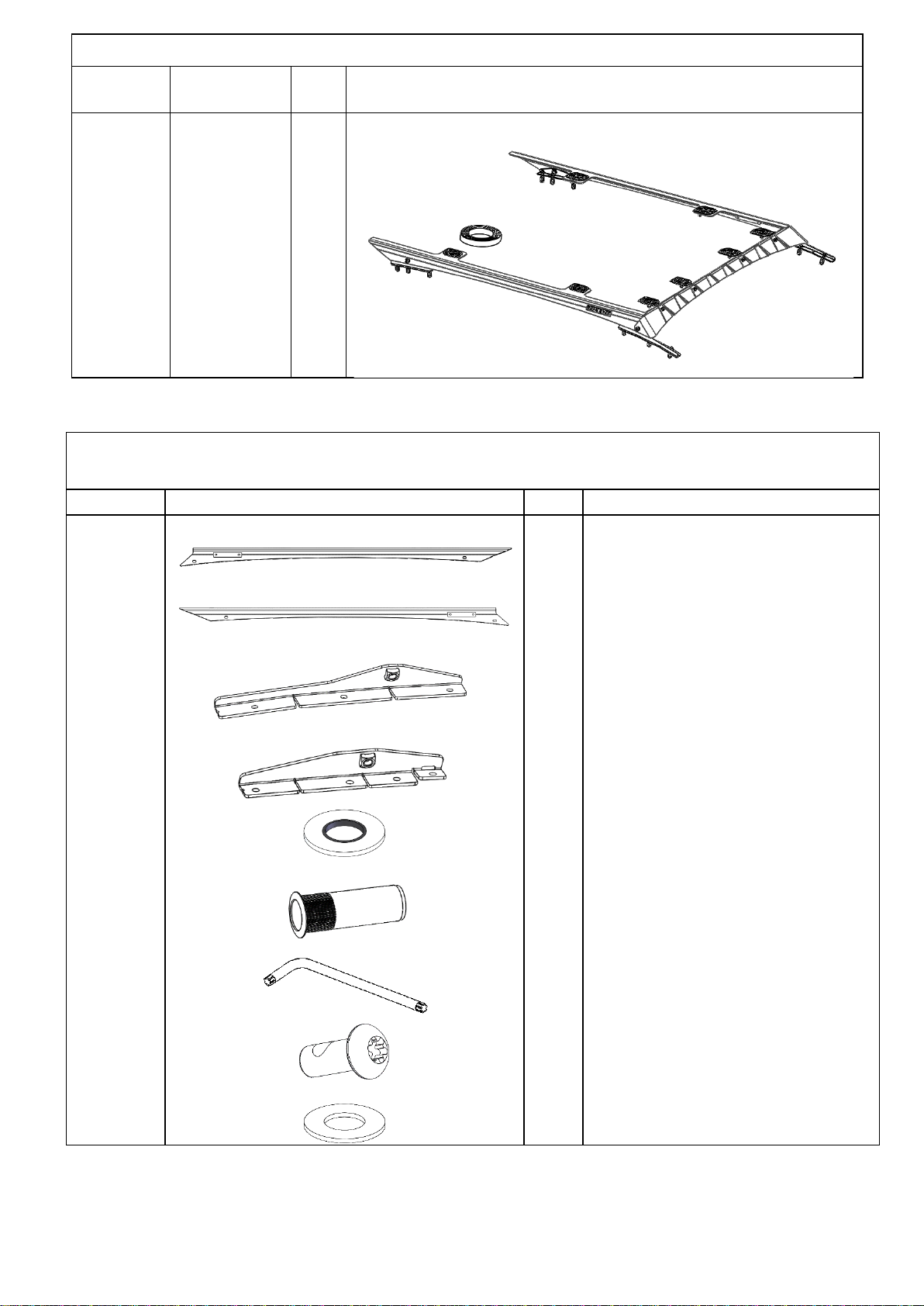
PARTS LISTING 17940080
PART NO.
PICTURE
QTY
DESCRIPTION
3750573L
1
BLADE BRACKET RANGER LH
3750573R
1
BLADE BRACKET RANGER RH
4655165
L&R
1 PR
FRONT MOUNTING FOOT L&R
4655166
L&R
1 PR
REAR MOUNTING FOOR L&R
4584415
12
M8 WASHER FLAT - BONDED
6151996
12
NUTSERT M6x1.0
6151934
1
TORX ALLEN KEY
6151625
4
M8 X 1.25 X 25 BUTTON HEAD
TORX - BLK
4581085
16
M8 WASHER FLAT - BLACK

Last Rev Date: 21/09/2022
Page 5 of 19
Fitting instructions# 37801108
Copyright © 2022 by ARB Corporation Limited. All rights reserved; this document must not be reproduced without the express authority of ARB Corporation Ltd
6152008
3750574
3750575
6151475
3195184
6151921
6151212
4584329
6151459
668PB028
12
1
4
4
8
12
12
6
6
1
FLANGE HEAD BOLT M6x25
FRONT DIFFUSER
DIFFUSER MOUNT BRACKET
M6 U-NUT
M8 STUD PLATE
M8 X 20 STUD - BLACK
M8 X 1.25 NYLOC NUT - BLACK
M6 WASHER FLAT - BLACK
M6 BTN HEAD SCREW –BLACK
24mm FOAM TAPE ROLL
6781408
1
DOUBLE SIDED TAPE
Last Rev Date: 21/09/2022
Page 6 of 19
Fitting instructions# 37801108
Copyright © 2022 by ARB Corporation Limited. All rights reserved; this document must not be reproduced without the express authority of ARB Corporation Ltd
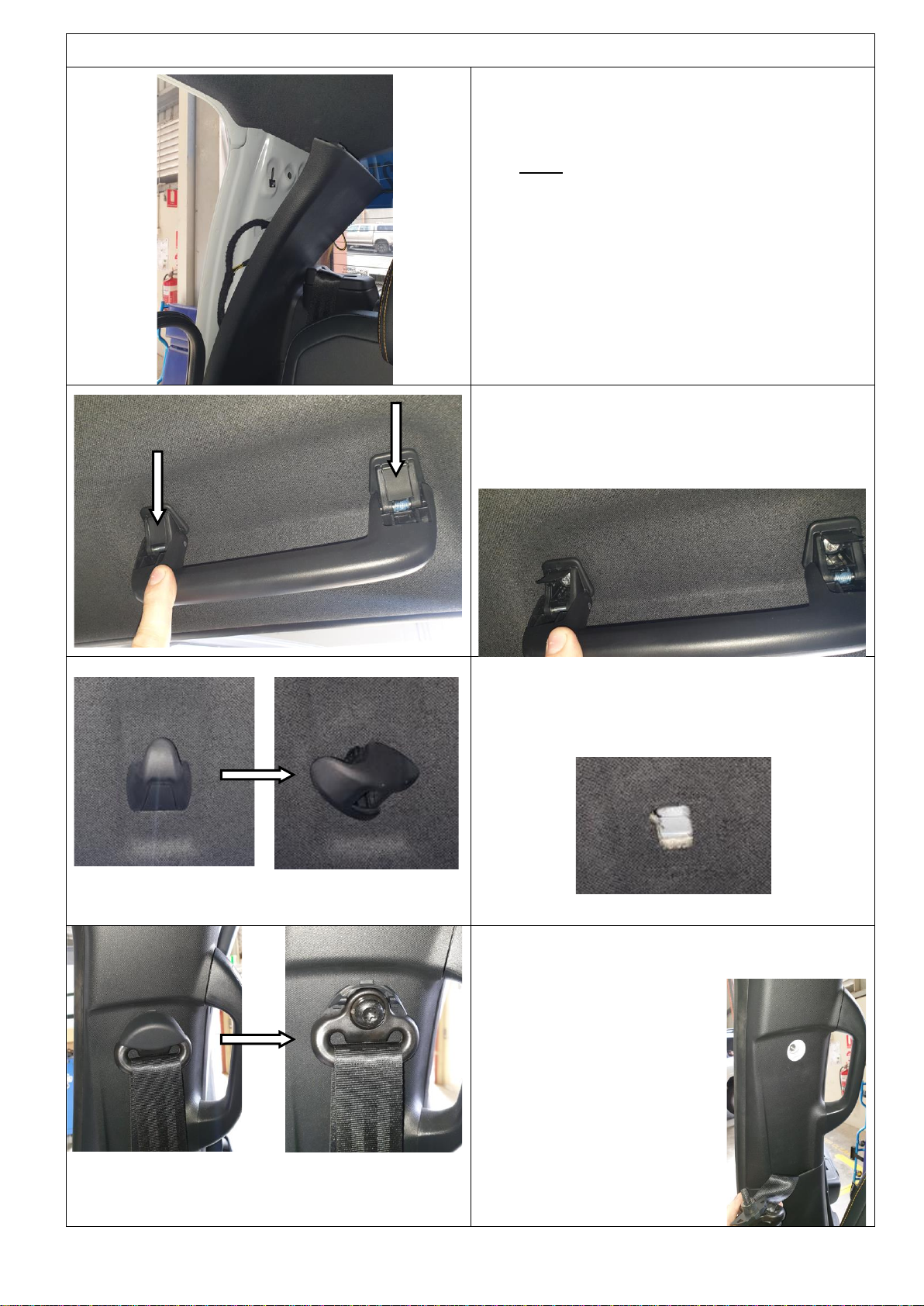
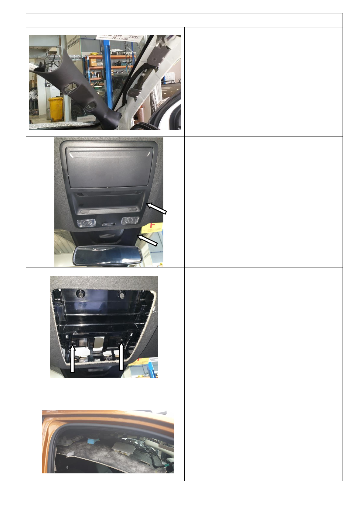
FITTING PROCEDURE
The interior roof lining needs to be
dropped to install the cab rack kit.
Note: Ensure you retain all fasteners and
clips to use when reinstalling the roof lining.
1. Pull back the door seal on the top half of the
rear door jamb. Unclip and pull back the side
rear pillar trims on both sides.
2. Remove the front and rear roof grab handles.
This is done by removing plastic covers to
expose the torx head screws.
3. Remove the centre cap of the rear window
hooks and rotate 45deg.
Pull the hooks out.
4. On the B-pillar, remove the plastic cap to
expose the retaining bolt on both front seat
belts.
Undo the Torx head bolt
on each front seat belts
and remove.
Allow the seatbelt to
hang down as shown.
Last Rev Date: 21/09/2022
Page 7 of 19
Fitting instructions# 37801108
Copyright © 2022 by ARB Corporation Limited. All rights reserved; this document must not be reproduced without the express authority of ARB Corporation Ltd
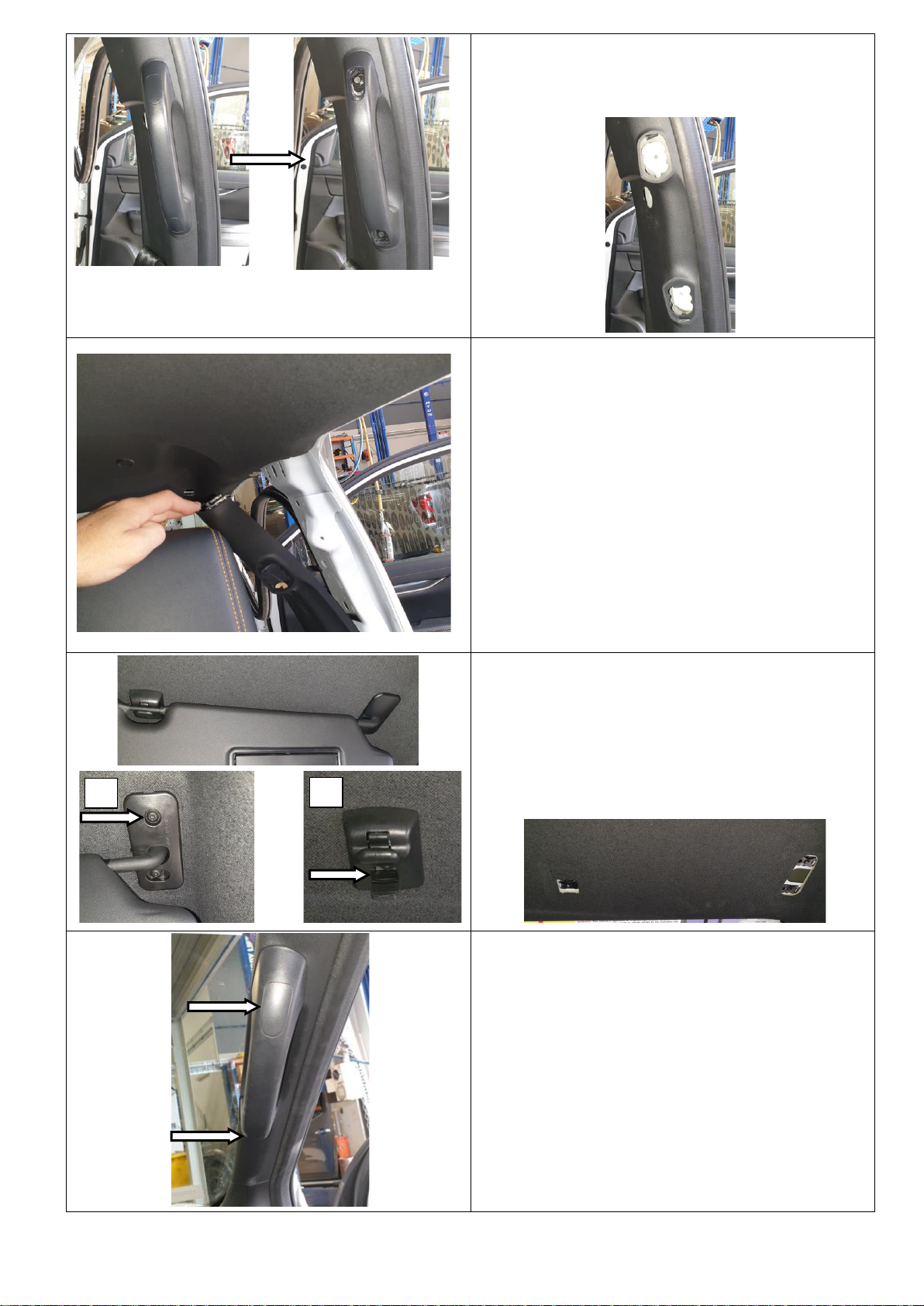
5. Remove the plastic caps on the B-pillar grab
handles to expose the torx strews.
Remove torx screws to remove the handles.
6. Unclip and remove the B-pillar plastic trim on
both sides.
7. Remove the front sun visors (A) by using a
small flat blade screwdriver to unclip the
plastic cover exposing the hex head screw.
Remove the visor retaining clips (B) by
removing the torx head screws.
8. Remove the grab handle on the RHS A-pillar
trim. There are two small hex bolts behind the
plastic caps.
A
B
Last Rev Date: 21/09/2022
Page 8 of 19
Fitting instructions# 37801108
Copyright © 2022 by ARB Corporation Limited. All rights reserved; this document must not be reproduced without the express authority of ARB Corporation Ltd
FITTING PROCEDURE
9. Unclip the A-pillar plastic trim.
10. Unclip the overhead console.
Disconnect the 2x electrical plugs running to
the unit.
Unclip the plastic trim above the rear vision
mirror
11. Remove the 2x torx screws.
12. The roof lining can now be dropped down.
The roof lining wiring harness is glued to the
roof lining so just let it hang as shown.

Last Rev Date: 21/09/2022
Page 9 of 19
Fitting instructions# 37801108
Copyright © 2022 by ARB Corporation Limited. All rights reserved; this document must not be reproduced without the express authority of ARB Corporation Ltd
13. Remove the aluminum gutter trims from the
roof. There is a large nut on the ends of each
trim on the inside of the roof skin.
14. Remove the rear pieces on each roof gutter
trim.
These end pieces will be reused during the
installation of the roof rack kit.
Discard all other items.
Note: If vehicle has rubber trims, skip to
step 16.
15. Drill out the threaded holes on the end trims
to 7.0mm as shown.
Warning: The following steps must
be followed with care not to cause
any damage to the curtain air bag
system on the vehicle.

Last Rev Date: 21/09/2022
Page 10 of 19
Fitting instructions# 37801108
Copyright © 2022 by ARB Corporation Limited. All rights reserved; this document must not be reproduced without the express authority of ARB Corporation Ltd
16. Using a rivnut gun, fit rivnuts to the front and
rear holes on both roof gutters as shown.
Rear holes need the rivnut installed in the
centre of the slot.
Note: Ensure the rivnuts are done up tight.
If they are not installed correctly, they may
leak.
When installing the rivnuts, make sure:
-
Rivnut is perpendicular to the sheet metal.
- Rivnut is fully compressed (refer image).
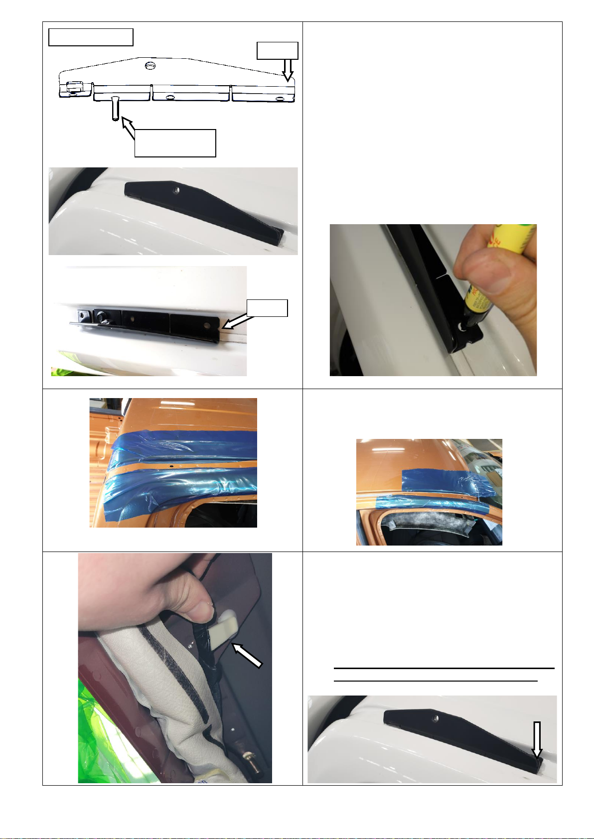
17. Mount the 2x front feet to the front rivnuts
fitted in step 16 using 1x M6 flange bolt per
foot as shown in the top image.
The front of the foot meets up with the
windscreen as shown.
Centralize the feet and mark the hole centres
of the other 2x holes per foot.
Remove the feet and use a centre punch on
the marks.
FRONT FEET
Front
Use this hole for
fitment in rivnut
Foot meets up
with windscreen
!
!
X
NOT OK
OK
Last Rev Date: 21/09/2022
Page 11 of 19
Fitting instructions# 37801108
Copyright © 2022 by ARB Corporation Limited. All rights reserved; this document must not be reproduced without the express authority of ARB Corporation Ltd
18. Mount the 2x rear feet to the rear rivnuts fitted
in step 16 using 1x M6 flange bolt per foot as
shown in the top image.
Note: The front of the foot has a small
notch as shown.
Centralize the feet and mark the hole centres
of the other 2x holes per foot.
Remove the feet and use a centre punch on
the marks.
19. Use low tack film or similar to protect the
areas around holes that need drilling as
shown.
20. Unclip the airbag wiring harness from the
vehicle roof on both sides (shown in left
image).
The below image shows the position of the
clips on the rear of the vehicle roof.
Warning: This wiring loom must be moved
out of the way before drilling the holes.
REAR FEET
Front
Use this hole for
fitment in rivnut
Notch

Last Rev Date: 21/09/2022
Page 12 of 19
Fitting instructions# 37801108
Copyright © 2022 by ARB Corporation Limited. All rights reserved; this document must not be reproduced without the express authority of ARB Corporation Ltd
21. Drill the 8x mounting holes in the gutters out
to ø10.0mm using a step drill.
*See drill specs on page 2
NOTE: Use a shop-vac directly underneath
the hole being drilled to ensure no metal
debris gets caught on the air bags or roof
lining.
Hint: Use the nozzle of the shop-vac to
pull the air bags and wiring away from the
area being drilled as shown in the “Inside
View” image.
22. Using a rivnut gun, fit rivnuts to the 8x holes.
There should now be 12x rivnuts installed in
the roof.
Note: Ensure the rivnuts are done up tight.
If they are not installed correctly, they may
leak.
23. Measure and cut 4x pieces of foam seal to fit
on the underside of the mount feet.
Inside View
VAC NOZZLE

Last Rev Date: 21/09/2022
Page 13 of 19
Fitting instructions# 37801108
Copyright © 2022 by ARB Corporation Limited. All rights reserved; this document must not be reproduced without the express authority of ARB Corporation Ltd
24. Fit the foam seal on the feet. Using a 7.0mm
drill bit, drill through the mount feet holes to
open up the foam seal.
25. Attach the aluminum trims to the rear feet
(prepared in step 15) using 1x M6 button
head screw, washer and nyloc nut.
Bolt the front and rear mount feet to the roof
using M6 flange head bolts & rubber bonded
washers as shown.
Tighten all 12x M6 bolts to specified torque.
M6 - 9 Nm.
Note: For vehicles with a rubber trim:
The rear of the trim will need to be cut to fit and
attached with double sided tape as shown
below:
Aluminum Trim
M6 button head screw
M6 washer
M6 nyloc nut
M6x25 flange head bolt
bonded washer

Last Rev Date: 21/09/2022
Page 14 of 19
Fitting instructions# 37801108
Copyright © 2022 by ARB Corporation Limited. All rights reserved; this document must not be reproduced without the express authority of ARB Corporation Ltd
If fitting 1780400 or 1780410 wiring kit, fit
now. Refer to page 19 of the instructions
for location.
26. The interior of the vehicle can now be
reassembled by completing steps 1-12 in
reverse order.
The torque spec for the seat belt bolts
removed in step 4 is:
M10 Seat Belt Bolts - 48 Nm.
Note: Ensure there is no metal debris left
on or around the curtain airbags. Use the
shop vac to carefully clean away any
debris left from the drilling process.
27. Using a tape measure, measure across the
vehicle between the middle of the hole on the
outside face of the front and rear set of
mounting brackets. Make a note of each
measurement.
Position
Distance
Front
Rear
28. Place the BASE RACK face down on a clean
flat surface. Provide protection to the top face
of BASE RACK to avoid marking of surfaces
29. Insert 2, M8 x 25 Studs into 4 of the Stud
Plates as shown.
Measured
distance
Outside
hole
Generic Image
Top face of BASE RACK
Last Rev Date: 21/09/2022
Page 15 of 19
Fitting instructions# 37801108
Copyright © 2022 by ARB Corporation Limited. All rights reserved; this document must not be reproduced without the express authority of ARB Corporation Ltd
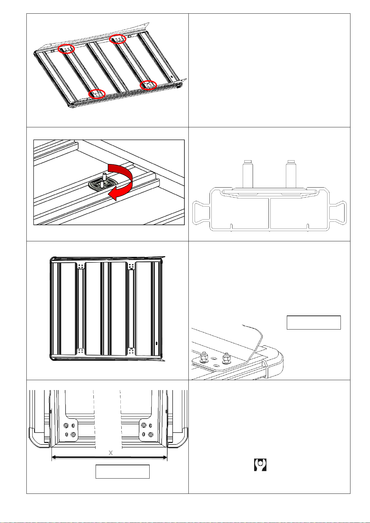
30. Check the position of the mounting plates
(circled in image) on the blade brackets in
relation to the channels on the BASE RACK.
31. Insert the previously assembled stud plates
into the correct BASE RACK channels.
Rotate the plates 90 degrees.
32. Flip the blade brackets over so they are
upside down and carefully place on top of the
BASE RACK. When doing so ensure the M8
studs in the stud plates go through the slots.
Then secure the blade brackets to the BASE
RACK using M8 flat washers and nyloc nuts.
Do not fully tighten, allowing each blade to
move.
33. Using the previously recorded
measurements, adjust the location of the
blade bracket on the BASE RACK.
Ensure the distance between the blade
bracket and the edge of the tray is the same
on both sides. Fully tighten all M8 nyloc nuts
to specified torque.
M8 - 22Nm
Generic Image
x
Generic Image
Last Rev Date: 21/09/2022
Page 16 of 19
Fitting instructions# 37801108
Copyright © 2022 by ARB Corporation Limited. All rights reserved; this document must not be reproduced without the express authority of ARB Corporation Ltd
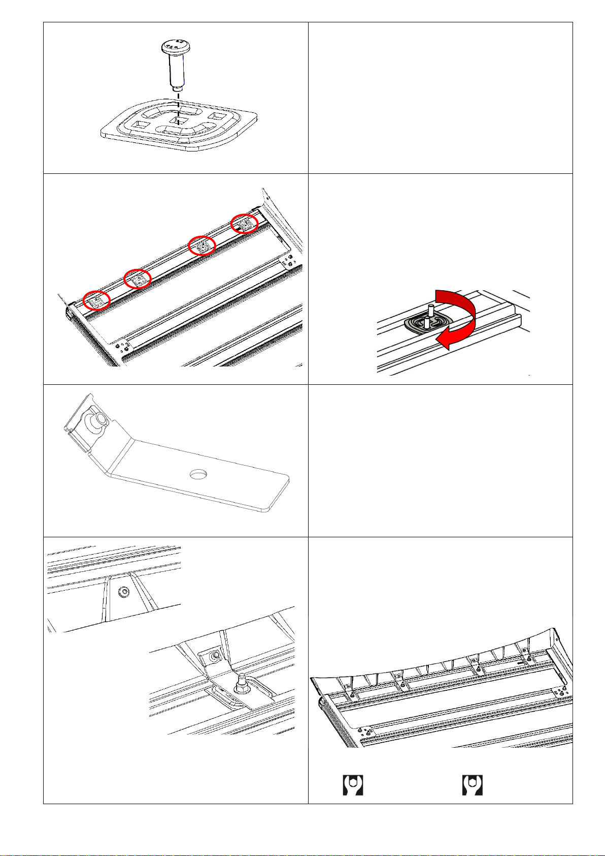
34. Insert an M8 x 25 Stud into 4 of the Stud
Plates as shown.
35. Insert the previously assembled stud plates
into the front BASE RACK channel. Rotate
the plates 90 degrees.
36. Fit M6 U-nuts to the 4x diffuser brackets as
shown. The thread needs to be on the inside.
37. Loosely fit the diffuser to the mounts and
brackets as shown. Use an M8 nyloc nut and
washer to hold the diffuser brackets to the
stud plates. Use M6 screws and washers to
hold the diffuser to the brackets.
38. Tighten to specified torque.
M6 - 9Nm M8 - 22Nm

Last Rev Date: 21/09/2022
Page 17 of 19
Fitting instructions# 37801108
Copyright © 2022 by ARB Corporation Limited. All rights reserved; this document must not be reproduced without the express authority of ARB Corporation Ltd
39. If fitting a BASE RACK lightbar it should
be fitted to the BASE RACK at this point.
Refer to instructions provided with the
BASE RACK light bar for fitting details.
40. With assistance, carefully place the
BASERACK on the vehicle so the inside of
the blade brackets rests on the outside of the
mounting brackets. The entire BASERACK
assembly should be clear of the vehicle roof.
All mounting holes/slots should align closely.
41. Note: Place protective material on roof to
reduce the risk of accidental damage to
vehicle when mounting the BASERACK to the
vehicle.
42. Confirm BASE RACK is correctly aligned to
vehicle. If it is not it is recommended to
remove the BASE RACK from the vehicle roof
and repeat the mounting process from the
measurement step 27.
43. Use the M8 Button head Torx screws and M8
Black washers to secure the roof tray to the
roof mounting brackets. Tighten all screw to
the specified torque.
M8 - 22Nm
Last Rev Date: 21/09/2022
Page 18 of 19
Fitting instructions# 37801108
Copyright © 2022 by ARB Corporation Limited. All rights reserved; this document must not be reproduced without the express authority of ARB Corporation Ltd
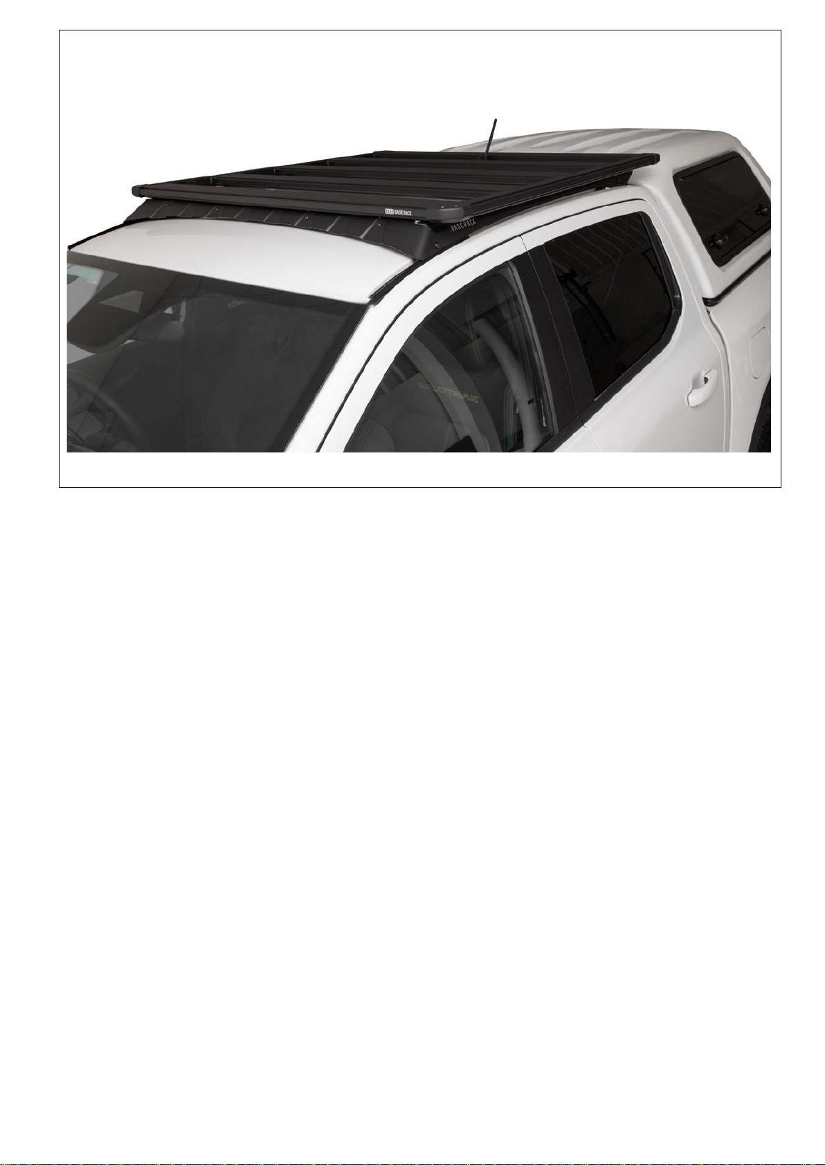
FITTED PRODUCT –2022 Ford Ranger with 1770070 Base Rack

Last Rev Date: 21/09/2022
Page 19 of 19
Fitting instructions# 37801108
Copyright © 2022 by ARB Corporation Limited. All rights reserved; this document must not be reproduced without the express authority of ARB Corporation Ltd
OPTIONAL STEP FOR BASE RACK WIRING KIT
(1780400 & 1780410 SOLD SEPARATELY)
These steps are a vehicle specific supplement to the main instruction, this instruction
should be used in parallel. Read both instructions before proceeding.
1. The recommended location for the wiring
kit for this vehicle is the rear, left hand
side.
2. The location provided has been chosen to
provide a safe passage away from vehicle
components (airbags, vents, etc) and
integrated to the rack.
! CAUTION –THIS STEP MAY REQUIRE
DISASSEMBLY OF SEAT BELT MOUNTS
AND WORK IN THE PROXIMITY OF
CURTAIN AIR BAGS!
3. Use the hole locations shown. Always
verify they are clear inside the cabin
before drilling.
4. Run the wiring backward then follow and
secure to the existing wiring loom down
the rear pillar.
ENSURE THE WIRING IS BEHIND THE
AIRBAG.
Obstruction of the airbag will prevent
proper inflation and effectiveness.
This manual suits for next models
1
Table of contents
Other ARB Automobile Accessories manuals


ARB
ARB Airlocker RD158 User manual

ARB
ARB RD121 Operating and maintenance instructions

ARB
ARB 6174921 User manual

ARB
ARB Air Locker RD204 User manual

ARB
ARB Airlocker RD143 User manual

ARB
ARB 3432090 User manual

ARB
ARB 3434040 User manual

ARB
ARB LINX LX100 User manual

ARB
ARB INTENSITY IQ User manual

ARB
ARB 3540320 User manual


