ARB 3940420 User manual

Last Rev Date 17/05/2019
Page 1 of 36
Fitting instructions# 3789528
Copyright © 2005 by ARB Corporation Limited. All rights reserved, this document must not be reproduced without the express authority of ARB Corporation Ltd
Part Number:
3940420
Product Description:
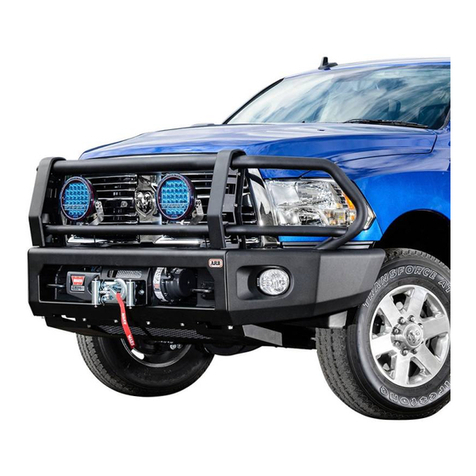
SUMMIT SAHARA BULL BAR
Suited to vehicle/s:
FORD RANGER PX MK2 & EVEREST (NOT TITANIUM)
Optional Kits:
5100310 SAHARA TUBE KIT PXII RANGER
5100230 BUFF KIT 2 PCE REAR SAHARA BUMPER
3500720 WINCH INSTALL KIT
3500640 ARB AUX FOG LIGHT ADAPTOR
3500530 ARB AUX FOG LIGHT LOOM (2015 ON WILDTRAK,
EVEREST & ON-FACTORY FOG LAMP VEHICLES)
3500680 FOG LAMP HOUSING CLEAR LENS KIT
3500590 FOG LIGHT KIT (LH&RH LIGHTS)
3540200 ADAPTIVE CRUISE CONTROL KIT
3540190 ADAPTIVE CRUISE CONTROL COVER
NOTE: ARB recommends purchase of correctly colour coded sensors from a Ford dealer.
Painting over sensors is not recommended as sensor operational faults can result.
WARNING
REGARDING VEHICLES EQUIPPED WITH SRS AIRBAG;
When installed in accordance with these instructions, the front protection bar does not affect operation of
the SRS airbag.
ALSO, NOTE THE FOLLOWING:
This product must be installed exactly as per these instructions using only the hardware supplied.
In the event of damage to any bull bar component, contact your nearest authorised ARB stockist. Repairs or
modifications to the impact absorption system must not be attempted.
Do not use this product for any vehicle make or model, other than those specified by ARB.
Do not remove labels from this bull bar.
This product or its fixing must not be modified in any way.
The installation of this product may require the use of specialized tools and/or techniques
It is recommended that this product is only installed by trained personnel
These instructions are correct as at the publication date. ARB Corporation Ltd. cannot be held responsible
for the impact of any changes subsequently made by the vehicle manufacturer
During installation, it is the duty of the installer to check correct operation/clearances of all components
Work safely at all times
Unless otherwise instructed, tighten fasteners to specified torque
ARB 4x4 ACCESSORIES
Corporate Head Office
42-44 Garden St Tel: +61 (3) 9761 6622
Kilsyth, Victoria Fax: +61 (3) 9761 6807
AUSTRALIA 3137
www.arb.com.au

Last Rev Date 17/05/2019
Page 2 of 36
Fitting instructions# 3789528
Copyright © 2005 by ARB Corporation Limited. All rights reserved, this document must not be reproduced without the express authority of ARB Corporation Ltd
GENERAL CARE AND MAINTENANCE
By choosing an ARB Bar, you have bought a product that is one of the most sought after 4WD products in the
world. Your bar is a properly engineered, reliable, quality accessory that represents excellent value. To keep your
bar in original condition it is important to care and maintain it following these recommendations:
Prior to exposure to the weather your bar should be treated to a Carnauba based polish on all exposed
surfaces. It is recommended that this is performed on a six monthly basis or following exposure to salt, mud,
sand or other contaminants.
As part of any Pre Trip Preparation, or on an annual basis, it is recommended that a thorough visual
inspection of the bar is carried out, making sure that all bolts and other components are torqued to the correct
specification. Also check that all wiring sheaths, connectors, and fittings are free of damage. Replace any
components as necessary. This service can be performed by your local authorized ARB Stockist
Important electrical system information
The 2011-On Ford Ranger uses an advanced wiring system allowing new chassis control systems to be
used. Due to this, placing large amounts of additional load to the wiring harness may trigger faults in the
ECU or cause permanent damage to the wiring harness.
To prevent overloading the turn and clearance lights must be activated through relays. Relay looms are
provided within this kit to wire these lights. For further reference please see the attached wiring diagram at
the end of these instructions.
Maintenance of adaptive cruise control components (if fitted, available on 2015 ON Ranger) must only be
performed by an authorized ARB workshop. No adjustments to the radar and/or bull bar are permissible
following original fitment unless conducted by your local authorized ARB stockist. Regular cleaning of the
radar must be carried out in order to ensure optimal operation. Ensure that no foliage, dirt or material is
obstructing the radar‟s field of vision as this may impact the performance of the radar
FITTING REQUIREMENTS
REQUIRED TOOLS FOR FITMENT OF PRODUCT:
BASIC TOOL KIT
ELECTRIC DRILL & Ø2, Ø5.5,Ø7 & Ø10MM BITS
JIG SAW OR MULTI-TOOL WITH BLADE
SUITABLE FOR PLASTIC
MATTE BLACK SPRAY PAINT
FILE OR SAND PAPER
MASKING TAPE
BASIC MEASURING TOOLS
ELECTRICAL TAPE (BLACK)
CONVOLUTED TUBE (7MM & 12MM)
HACK SAW OR EQUIV.
TORQUE WRENCH 9-100 Nm CAPACITY
LARGE G-CLAMP
HAVE AVAILABLE THESE SAFETY ITEMS WHEN FITTING PRODUCT:
Protective eyewear
Hearing protection
NOTE: „WARNING‟ notes in the fitting procedure relate to OHS situations, where to avoid a
potentially hazardous situation it is suggested that protective safety gear be worn or a safe work
procedure be employed. If these notes and warnings are not heeded, injury may result.
FASTENER TORQUE SETTINGS:
SIZE
Torque (Nm)
Torque (ftlb)
Plastics Screws
0.8
0.6
M6
9
7
M8
22
16
M10(TOP FRAME ONLY)
22
16
M10
44
32
M12
77
57
M16
90
66

Last Rev Date 17/05/2019
Page 3 of 36
Fitting instructions# 3789528
Copyright © 2005 by ARB Corporation Limited. All rights reserved, this document must not be reproduced without the express authority of ARB Corporation Ltd
APPLICATION.
PART NO.
DESCRIPTION
QTY
FIT MOUNT
BRACKET TO
CHASSIS
3759563
BRACKET CHASSIS MOUNT RANGER LRG RAD
1
3759574R
BRACKET CHASSIS BRACE INNER RIGHT
1
3759574L
BRACKET CHASSIS BRACE INNER LEFT
1
3759575R
BRACKET CHASSIS BRACE OUTER RIGHT
1
3759575L
BRACKET CHASSIS BRACE OUTER LEFT
1
3759576R
BRACKET BULL BAR BRACE RIGHT
1
3759576L
BRACKET BULL BAR BRACE LEFT
1
4584375
SPACER Ø1 ¼” 15MM THICK
2
5848427
PACKER CHASSIS 5MM THICK
4
6151357
BOLT SEMS M10 X 30 ZP Gd 8.8
10
4581011
WASHER FLAT, M12 x 27 x 4
10
4581083
WASHER FLAT, M10 x 21 x 2 ZP
2
4581050
WASHER SPRING 1/2 x 3/16 x 3/16 ZP
10
4581048
WASHER SPRING M10 TZP480
2
6151360
BOLT M12 x 1.75 x 35 Gd 8.8 ZP
10
6151428
NUT FLANGE M12 X 1.75 ZP
10
6151456
BOLT M10 x 1.5 x 45 Gd 8.8 ZP
2
6151727
BOLT HXFL M16 x 2.0 x 35 FT PC8.8 TZP
2
6151728
NUT FL SM M16 x 2.0 PC8 TZP
2
FIT BAR TO
MOUNT
BRACKET
4584376
SPACER Ø1 ¼ “ 35MM THICK
2
6151357
BOLT SEMS M10 X 30 ZP Gd 8.8
4
6151306
NUT CAGED M12 1.8-3.2
6
4581050
WASHER SPRING 1/2 x 3/16 x 3/16 ZP
6
6151360
BOLT M12 x 1.75 x 35 Gd 8.8 ZP
4
6151168
BOLT M12 x 1.75 x 80 CL8.8 ZP
2
3194293
PLATE NUT MOUNT RANGER T6
2
4581007
WASHER FLAT 1/2 x 1.1/2 x 4MM SILVER
6
6151321
NUT FLANGE M10 x 1.5 ZP
12
MISC
3789424
CUTTING TEMPLATE BUMPER RANGER 15 ON
1
6151349
8 - 15 X 15mm BUTTON HEAD SELF TAPPING GP
4
180302
CABLE TIE 4.8 X 180 MM BLACK
12
6191037
PINCH WELD 1000mm
1
FIT LICENSE
PLATE
BRACKET
6151213
BOLT M6 x 1.0 x 20 Gd8.8 BZ
3
4581287
WASHER SPRING M6 x 2.5 x 1.6 BLK ZN
3
4584295
WASHER FLAT M6 X 12 X 1.3 BLK ZN
3
6151128
NUT FLANGE M6 x 1.0 ZP
3
3759488
BRACKET LIC PLATE FIXED LARGE RAD
1
6821189
GROMMET RND FC 1500 080 090
2
6151384
SCREW 10G x 5/8 SELF TAPPING
2
FIT WINCH
ACCESS PANEL
6151213
BOLT M6 x 1.0 x 20 Gd8.8 BZ
4
4581287
WASHER SPRING M6 x 2.5 x 1.6 BLK ZN
4
4584295
WASHER FLAT M6 X 12 X 1.3 BLK ZN
4
6151128
NUT FLANGE M6 x 1.0 ZP
4
6522985
PRESS FORM WINCH COVER PANEL
1

Last Rev Date 17/05/2019
Page 4 of 36
Fitting instructions# 3789528
Copyright © 2005 by ARB Corporation Limited. All rights reserved, this document must not be reproduced without the express authority of ARB Corporation Ltd
PARTS LISTING
APPLICATION.
PART NO.
DESCRIPTION
QTY
FIT UNDER
PANELS
6522940R
PANEL UNDER WING RANGER 11ON
LRG RAD
1
6522940L
PANEL UNDER WING RANGER 11ON
LRG RAD
1
3758957
BRACKET WING PANEL RANGER T6
2
6151132
NUT FLANGE M8 x 1.25 ZP
7
4581082
WASHER FLAT, M6 x 19 x 1.6 BZ
10
4581047
WASHER SPRING M8 x 3/32 x 3/33 BLK
14
4581287
WASHER SPRING M6 x 2.5 x 1.6 BLK ZN
10
6151234
BOLT M8 x 1.25 x 25 Gd 8.8 BP
14
6151213
BOLT M6 x 1.0 x 20 Gd8.8 BZ
10
6151300
NUT CAGED M6 2.6-3.5
10
6151301
NUT CAGED M8 3.3-4.7
7
6522838
PANEL SPLASH RANGER T6
1
3758956
BRACKET OE STONE SHEILD RANGER T6
1
6151357
BOLT SEMS M10 X 30 ZP Gd 8.8
2
6151321
NUT FLANGE M10 x 1.5 ZP
2
4581307
WASHER FLAT, M8 x 20 x 2 BLK ZN
14
LIGHTS AND
MOULDINGS
6821287
LAMP LED INDICATOR CLEARANCE
1
3163082
KIT SURROUND ARB FOGLIGHT
1
6821116
GROMMET NYLON SNAP IN TYPE
4
3500880
GRILLE SPLIT PAN KIT
1
5100200
BUFF KIT 2PCE FRONT SECTION
1
5100210
BUFF KIT 2PCE REAR UPRIGHT BAR
1
DIGITAL RADIO
ANTENNA
RELOCATION
6151464
SCREW BUTTON HEAD M8 x 1.25 x 25 BLK ZN
2
4581047
SPRING WASHER M8 BLK ZN
2
4581307
WASHER FLAT M8 BLK ZN
2
6151548
NUT FLANGE M8 x 1.25
2
PARKING
SENSORS
3500960
SENSOR SURROUND KIT
1
3163222
BLANKING PLUGS
2
WING BRACE
4681588R
BRACE WING RH
1
4681588L
BRACE WING LH
1
6151045
BOLT M10 x 1.5 x 25
8
4581083
WASHER FLAT, M10 x 21 x 2 ZP
8
4581048
WASHER SPRING M10 TZP480
8
6151321
NUT FLANGE M10 x 1.5 ZP
8

Last Rev Date 17/05/2019
Page 5 of 36
Fitting instructions# 3789528
Copyright © 2005 by ARB Corporation Limited. All rights reserved, this document must not be reproduced without the express authority of ARB Corporation Ltd
FITTING PROCEDURE
Note: Read the instructions thoroughly before
starting.
1. Open the bonnet and remove the screws and
retaining clips used to retain the plastic cover
above the grille.
Carefully detach plastic cover.
Note: Everest requires the 2 bolt securing air
duct to be removed.
FOR RANGER:
2. Remove the screws and retaining clips used
to retain grille.
Carefully detach grille piece from vehicle.
FOR EVEREST:
3. Remove 2 screws retaining grille.
Retain screws and clips.
Note: Take note where fasteners are removed
from as some have to be replaced later in the
fitment.
4. Remove all the bumper fasteners along the
inside edge of the wheel arches.
FOR RANGER:
5. Remove all the fasteners securing the bottom
of the bumper to the vehicle.
EVEREST

Last Rev Date 17/05/2019
Page 6 of 36
Fitting instructions# 3789528
Copyright © 2005 by ARB Corporation Limited. All rights reserved, this document must not be reproduced without the express authority of ARB Corporation Ltd
FITTING PROCEDURE
FOR RANGER:
6. Undo and remove the screws and plastic clips
behind the grille near the lower inner edge of
the head lights.
FOR RANGER:
7. Remove the screws and clips holding the
inner grille air deflectors to the vehicle.
8. Retain air deflectors, screws and clips.
FOR RANGER:
9. Carefully remove all clips used to retain
bumper to crash beam.
FOR EVEREST:
10. On both sides undo and remove the screws
behind the grille near the lower inner edge of
the head lights.
FOR EVEREST:
11. Remove all the fasteners securing RH SIDE
outer trim panel to the vehicle and detach.
Discard the panel.
12. Repeat on LH Side

Last Rev Date 17/05/2019
Page 7 of 36
Fitting instructions# 3789528
Copyright © 2005 by ARB Corporation Limited. All rights reserved, this document must not be reproduced without the express authority of ARB Corporation Ltd
FITTING PROCEDURE
FOR EVEREST:
13. Remove all the fasteners securing centre trim
panel to the vehicle and detach. Discard the
panel.
14. Disconnect all sensors and fog lights attached
to the bumper and allow them to hang loose.
NOTE: Parking sensor connector is on LH
side of bumper.
15. Starting on the RH side of the vehicle,
carefully pull the rear most corner away from
the vehicle un-clipping the bumper. With the
assistance of another person remove the
bumper from the vehicle and place in a safe
place where it will not be damaged.
FOR RANGER:
16. Remove the plastic panel attached to the front
cross beam by removing the plastic clips.
Discard the panel.
FOR EVEREST:
17. Remove the foam piece attached to the front
cross beam by removing the plastic clips.
Discard the foam piece.

Last Rev Date 17/05/2019
Page 8 of 36
Fitting instructions# 3789528
Copyright © 2005 by ARB Corporation Limited. All rights reserved, this document must not be reproduced without the express authority of ARB Corporation Ltd
FITTING PROCEDURE
18. If vehicle is fitted with radar, refer to fitting
instructions supplied with adaptive cruise
control kit (Part No. 3540200 - purchased
separately) for removal and relocation.
If not, proceed to step 19.
NOTE: Radars are initialised to each vehicle
and cannot be used on other vehicles.
19. Use a screw driver to push the 2 x plastic clips
inward from the front cross beam. Do not
remove the clips as they will be used later.
20. Remove the factory under panel and place in
a safe place. Do not completely remove the
rear bolts. Leave loose.
21. Remove the front cross beam and discard.

Last Rev Date 17/05/2019
Page 9 of 36
Fitting instructions# 3789528
Copyright © 2005 by ARB Corporation Limited. All rights reserved, this document must not be reproduced without the express authority of ARB Corporation Ltd
FITTING PROCEDURE
22. Remove screws retaining RH & LH
bumper retention blocks to vehicle and
remove the retention blocks from both
sides and set aside.
23. Remove and discard the inner guard
support brackets from both sides of the
vehicle.
24. Following fitting instructions 3789197 supplied in kit 6821287; install the LED combination
lamp looms (also supplied in same kit).
Notes:
-Use a test light or multimeter to pick the appropriate wire to attach the loom to.
-Cover each joint with either insulation tape or heat shrink tube.
- Use cable ties to secure all wiring
Function
LED
Wire
Vehicle Wire
RANGER
EVEREST
Ground
Black
BLK/Purple (RHS)
BLK/Yellow (LHS)
Indicator
Green
Blue/Orange (RHS)
Green/Blue (LHS)
Clearance
Red
Brown/Yellow (RHS)
Green/Yellow (LHS)
Pink/Yellow (RHS)
Green/Orange (LHS)
NOTE: The wiring in vehicles fitted with factory 35W fog lights (2015 ON Wildtrak Model or
Everest) is not suitable for running ARB fog lamps. Proceed to step 28.
For vehicles without factory fog lamps and where optional ARB fog lamps are to be fitted:
25. Install optional ARB wiring loom 3500530 and switch into vehicle. Refer to instructions supplied
with loom. Place switch inside cabin in a suitable position.
26. Connect optional ARB fog lights (# 3500590) to wiring loom.
27. Proceed to step 34.
CAUTION: Ensure that all cables are securely fastened away from sharp, abrasive or hot
surfaces.
INDICATOR
*LHS shown
EVEREST
RANGER
CLEARANCE

Last Rev Date 17/05/2019
Page 10 of 36
Fitting instructions# 3789528
Copyright © 2005 by ARB Corporation Limited. All rights reserved, this document must not be reproduced without the express authority of ARB Corporation Ltd
FITTING PROCEDURE
For vehicles with factory fog lamps:
28. The factory fog light switch can be used in
conjunction with the ARB loom 3500530 to
power the ARB fog lights.
29. Discard loom switch and thin yellow wire from
3500530.(Harness from bullet terminals to
switch)
30. Install ARB wiring loom 3500530 to vehicle.
Do not install switch or yellow wire with
fuse.
CAUTION: Ensure that all cables are securely
fastened away from sharp, abrasive or hot
surfaces.
31. Identify the black/white trigger wire from
3500530 as shown.
32. Connect the black/white trigger wire to the
positive terminal on the factory fog light wire
using the supplied scotch lock or a female
bullet connector.
33. Tape the bullet terminal from the black wire
from 3500530 to prevent short-circuits.
Securely fasten it away from sharp, abrasive or
hot surfaces.
Notes:
-Use a test light or multimeter to pick the
appropriate wire to attach the loom to.
-Check the operation of all lights wired during
bar fitment
34. Carefully mask the area surrounding each
side of the guard as shown (RH shown).
35. Thoroughly clean the area.
36. Using Matte Black spray paint, paint the
masked area.
37. Allow to dry.
REPEAT FOR LHS
38. If parking sensors are fitted, carefully unclip
sensors and sensor loom from bumper bar and
set aside for fitment to bull bar.
Cover black wire bullet
terminal with tape
Discard these items
Keep these items
Black/white trigger wire

Last Rev Date 17/05/2019
Page 11 of 36
Fitting instructions# 3789528
Copyright © 2005 by ARB Corporation Limited. All rights reserved, this document must not be reproduced without the express authority of ARB Corporation Ltd
FITTING PROCEDURE
BUMPER CUT FOR RANGER: STEP 39-61
If fitting to Everest skip to step 62
39. Place the bumper on a stand facing upwards.
40. Using masking tape, cover front corner section
of bumper.
41. Using ridge on bumper as a guide, mark a line
following the ridge across the front section of
bumper as shown.
42. Continue the line onto the bumper as shown
using the edge of bumper as a guide.
43. Mark a line perpendicular to bumper 30mm
inwards from locating hole on top surface as
shown until it meets line on bumper edge.
44. Using scissors carefully cut out the supplied
template.
30mm
RIDGE
30mm
TOP
TOP VIEW
LOOKING DOWN

Last Rev Date 17/05/2019
Page 12 of 36
Fitting instructions# 3789528
Copyright © 2005 by ARB Corporation Limited. All rights reserved, this document must not be reproduced without the express authority of ARB Corporation Ltd
FITTING PROCEDURE
45. Position template onto bumper as shown and
using a marker pen, mark contour onto bumper
until it meets other line on bumper.
46. Carefully remove the template and repeat
steps 39-45 for LHS.
47. Using a jig saw or similar, carefully cut along
marked lines.
48. De-bur the cut edges with a file or sandpaper.
Note: It is advised that you take steps to prevent
damage to the bumper when cutting such as
placing extra masking tape on the kept portion
of the bumper.
49. Position cut bumper onto bumper retention
block set aside and mark a line onto block as
shown using a white marker pen. (RH side
shown)
50. Remove cut bumper and carefully cut along
inside edge of marked line using a multitool.
51. Repeat for LHS.
52. Use a file or sandpaper to de-bur all cut
edges.
53. Set aside for re-fitment later on.
Warning: Cutting operations
can result in flying debris,
safety glasses should be
worn.
MARK LINE HERE
Warning: Cutting operations
can result in flying debris,
safety glasses should be
worn.

Last Rev Date 17/05/2019
Page 13 of 36
Fitting instructions# 3789528
Copyright © 2005 by ARB Corporation Limited. All rights reserved, this document must not be reproduced without the express authority of ARB Corporation Ltd
FITTING PROCEDURE
54. Place masking tape across front section of
grille where ridge is as shown.
55. Mark line onto grille 40mm below ridge in grille
as shown.
56. Using a multitool, carefully cut along marked
line.
57. De-bur the cut edges with a file or sandpaper.
58. For chrome grille, position pinch weld supplied
in kit along cut edge (centre the pinch weld
across width of grille).
59. Fit the two self tapping screws into the lower
section of the grille to join the two parts
together as shown
IF FITTING WINCH:
For Warn, Magnum and Bushranger control boxes,
additional cut out for grille is required.
60. Using a multitool cut a 240 X 40 mm section
out of lower section of grille.
61. Apply Pinch weld to cut edges.
40mm
Cut out central to grille
40mm
240mm
Warning: Cutting operations can result in flying
debris, safety glasses should be worn.
Warning: Cutting operations
can result in flying debris,
safety glasses should be worn.

Last Rev Date 17/05/2019
Page 14 of 36
Fitting instructions# 3789528
Copyright © 2005 by ARB Corporation Limited. All rights reserved, this document must not be reproduced without the express authority of ARB Corporation Ltd
FITTING PROCEDURE
BUMPER CUT FOR EVEREST: STEPS 62-78
62. Place the bumper on a stand facing upwards.
63. Place 50mm masking take below the ridge of
the bumper.
64. On the masking tape, mark a line across the
bumper 5mm below the ridge line.
65. Below the grille place 50mm masking take
above the ridge of the bumper.
66. On the masking tape, mark a line 20mm
above from the ridge line.
67. On both sides of the bumper mark a vertical
line 100mm inboard of the edge of the grille.
68. Using scissors carefully cut out the supplied
template.
69. Position template onto bumper as shown and
using a marker pen, mark contour onto bumper
until it meets other line on bumper.
70. Carefully remove the template and repeat for
LHS.
RIDGE
5mm
RIDGE
20mm
100mm

Last Rev Date 17/05/2019
Page 15 of 36
Fitting instructions# 3789528
Copyright © 2005 by ARB Corporation Limited. All rights reserved, this document must not be reproduced without the express authority of ARB Corporation Ltd
FITTING PROCEDURE
71. Using a jig saw or similar, carefully cut along
marked lines.
72. De-bur the cut edges with a file or sandpaper.
Note: It is advised that you take steps to prevent
damage to the bumper when cutting such as
placing extra masking tape on the kept portion
of the bumper.
73. Position cut bumper onto bumper retention
block set aside and mark a line onto block as
shown using a white marker pen. (RH side
shown)
74. Remove cut bumper and carefully cut along
inside edge of marked line using a multitool.
75. Repeat for LHS.
76. Use a file or sandpaper to de-bur all cut
edges.
77. Set aside for re-fitment later on.
IF FITTING WINCH:
If fitting winch additional cut out for bumper is
required.
78. Using a multitool, cut a section 240mm wide
and 5mm rearward of grille out of bumper.
NOTE:
-To aid in cutting of bumper removal of grille is
recommended.
-Keep bumper as one piece.
-Cut out is central to bumper.
Warning: Cutting operations
can result in flying metal
debris, safety glasses should
be worn.
MARK LINE HERE
Warning: Cutting operations
can result in flying debris,
safety glasses should be worn.
240mm
Cut out is central to grille
GRILLE
5mm
BUMPER
Warning: Cutting operations
can result in flying debris,
safety glasses should be
worn.

Last Rev Date 17/05/2019
Page 16 of 36
Fitting instructions# 3789528
Copyright © 2005 by ARB Corporation Limited. All rights reserved, this document must not be reproduced without the express authority of ARB Corporation Ltd
FITTING PROCEDURE
79. Remove clips from digital aerial antenna and
disconnect at connector.
80. Using a multitool carefully cut around metallic
plate corresponding to digital aerial antenna.
81. Retain antenna for remittent later on.
82. Unbolt digital radio module and unclip wire
harness.
83. Reattach digital radio module to outer most
bolting position and re-attach wire harness.
FOR RANGER:
84. Mark a line onto RH air deflector removed in
step 7 as shown 30mm below mounting tab.
85. Carefully cut along marked line and dispose of
lower section of air deflector.
86. De-bur the cut edges with a file or sandpaper.
87. Repeat for LH air deflector.
Warning: Cutting operations can result in flying
debris, safety glasses should be worn.
Mark line onto air deflector
Mounting tab
Warning: Cutting operations can result in flying
debris, safety glasses should be worn.

Last Rev Date 17/05/2019
Page 17 of 36
Fitting instructions# 3789528
Copyright © 2005 by ARB Corporation Limited. All rights reserved, this document must not be reproduced without the express authority of ARB Corporation Ltd
FITTING PROCEDURE
FOR RANGER:
88. The horn & harness will require to be rotated
for clearance to brackets. Unplug the harness
and remove the horn by removing the
mounting bolt.
89. Turn the horn over and loosen the retaining
nut. Rotate the arm 180°, and tighten the
retaining nut.
90. Re fit the horn in its original position and re-
route the harness to the top. Use cable ties if
necessary to reposition the harness.
FOR EVEREST:
91. On LH side remove 2 X screws holding duct to
vehicle.
Carefully detach duct piece from vehicle.
FOR EVEREST:
92. On the LH side carefully detach sensor.
93. Mark lines on air deflectors as shown.
94. Carefully cut along marked line and dispose of
lower section of air deflector.
95. De-bur the cut edges with a file or sandpaper.
Warning: Cutting operations can result in flying
debris, safety glasses should be worn.
Mark line onto air deflector
RH SIDE
LH SIDE
SENSOR
Mark line onto air deflector

Last Rev Date 17/05/2019
Page 18 of 36
Fitting instructions# 3789528
Copyright © 2005 by ARB Corporation Limited. All rights reserved, this document must not be reproduced without the express authority of ARB Corporation Ltd
FITTING PROCEDURE
FOR EVEREST
96. On RH side of lower air deflector mark a
vertical and horizontal line 15mm from the
centre of the clipping point.
97. Using the marked lines as a guide cut out a
50mm deep section form the deflector.
98. De-bur the cut edges with a file or sandpaper.
99. Fit the inner brace with the packer to the
chassis rail end. Ensure that the front edge is
pushed forward to the chassis flange. The
brace may need to be tapped to ensure a flush
fitment to the chassis is achieved.
Note: Ensure that packer is placed
correctly, with tabs pushed against brace.
100. Fit the M16 x 35 flange bolt through the front
access cut out of the front flange of the
chassis.
Clipping
point
Warning: Cutting operations can result in flying
debris, safety glasses should be worn.

Last Rev Date 17/05/2019
Page 19 of 36
Fitting instructions# 3789528
Copyright © 2005 by ARB Corporation Limited. All rights reserved, this document must not be reproduced without the express authority of ARB Corporation Ltd
FITTING PROCEDURE
101. Loosely position the outer bracket brace with
the packer to the chassis rail. Fit the M16
flange nut to hold it in place. Ensure that the
front edge is pushed forward to the chassis
flange.
NOTE: Ensure that packer is placed and
aligned correctly.
102. Fit 4 x M12 x 35 bolts, 4 x M12 flat washers, 4
x M12 Flange nuts.
M12 - 77 Nm.
NOTE: Do not fit the M12 spring washers these
will be fitted later on.
103. Using a spanner to hold the M16 flange bolt,
torque the M16 flange nut.
M16 - 90 Nm.
NOTE: Take care to torque as per requirement.
DO NOT torque outside the specs provided.
104. Using a large G-clamp, clamp the top rear
corner of the outer and inner brace together.
This will make the alignment of the top flange
easier for fitment of the brace.
105. Fit the M10 x 1.5 x 45 bolt, M10 spring washer
and M10 flat washer.

Last Rev Date 17/05/2019
Page 20 of 36
Fitting instructions# 3789528
Copyright © 2005 by ARB Corporation Limited. All rights reserved, this document must not be reproduced without the express authority of ARB Corporation Ltd
FITTING PROCEDURE
106. Fit the 2 x M10 x 30 SEMS bolts and M10
flange nuts to the bottom of the brackets to
clamp them together.
107. Fit the M10 x 30 SEMS bolt and M10 flange
nut to the brace and outer bracket.
108. Fit the 15mm wide spacer between the brace
and the outer bracket and then fit the M10
flange nut
109. Remove the 4 x M12 x 35 bolts, 4 x M12 flat
washers and 4 x M12 flange nuts fitted in step
102 and set aside for later.
Note: Keep all M10 fasteners loose and only
finger tight at this point.
Repeat steps 96-109 for the LH side.
110. Attach the mount bracket to the chassis end
plates using 4 x M10 x 30 SEMS bolts into the
captive nuts. Leave loose at this stage.
111. Attach the mount bracket to the chassis using
3 x M12 x35 bolts, 3 x M12 spring washers, 3 x
M12 flat washers and 3 x M12 Flange nuts.
112. Repeat on the LH side.
M12 - 77 Nm.
Table of contents
Other ARB Automobile Accessories manuals

ARB
ARB AIRLOCKER RD168 User manual
ARB
ARB DELUXE BULL BAR User manual
ARB
ARB 10900013 User manual
ARB
ARB Air Locker RD111 User manual
ARB
ARB ESPERANCE 802200 User manual
ARB
ARB Airlocker RD140 User manual

ARB
ARB Flinders User manual
ARB
ARB AIRLOCKER RD208 User manual
ARB
ARB 3432200 User manual
ARB
ARB AC08C User manual
Popular Automobile Accessories manuals by other brands

ULTIMATE SPEED
ULTIMATE SPEED 279746 Assembly and Safety Advice

SSV Works
SSV Works DF-F65 manual

ULTIMATE SPEED
ULTIMATE SPEED CARBON Assembly and Safety Advice

Witter
Witter F174 Fitting instructions

WeatherTech
WeatherTech No-Drill installation instructions

TAUBENREUTHER
TAUBENREUTHER 1-336050 Installation instruction
