Tool Kit for KK Crimp Terminals
Doc No: ATS-6381175HM elease Date: 12-06-06 UNCONTROLLED COPY Page 6 of 12
evision: K evision Date: 08-03-17
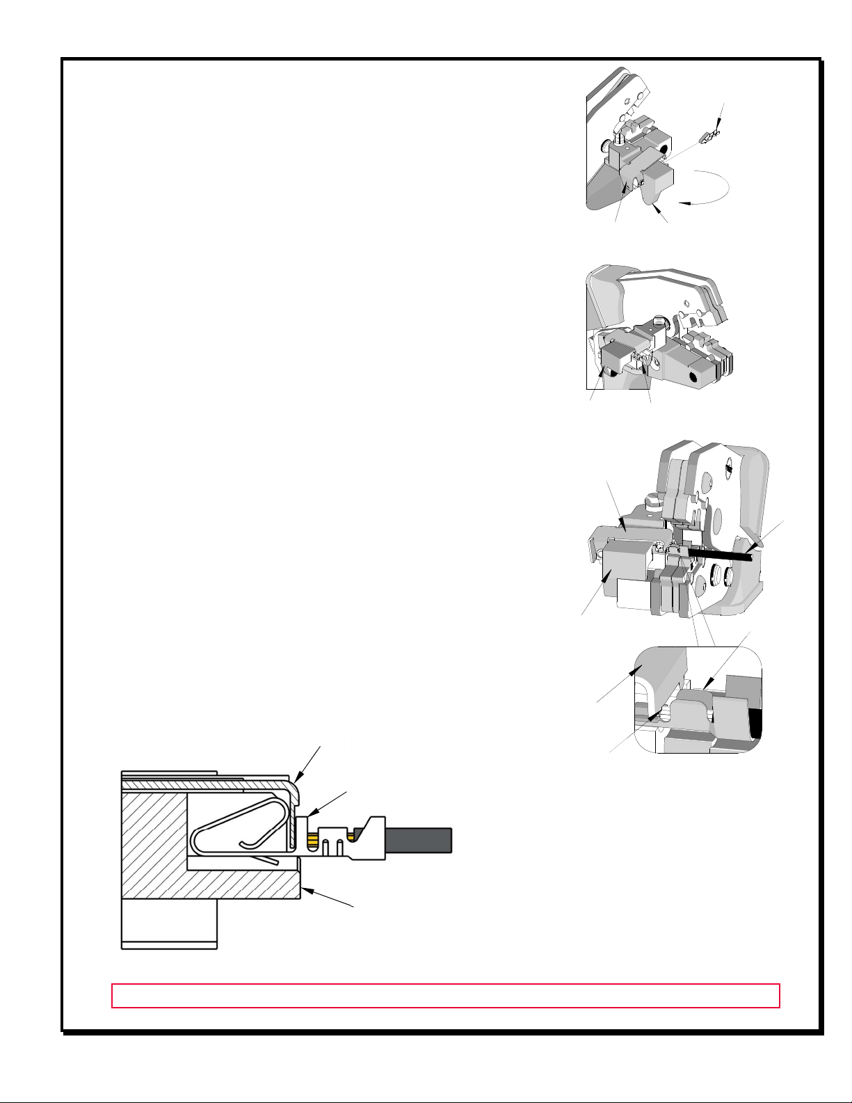
For the Battery Power Tool Operation:
1. Cycle the Battery Power Tool to crimp the terminal to the wire.
2. emove the crimped terminal from the terminal locator by pressing down on the wire stop and gently pulling on
the wire. The terminal locator can be in either position.
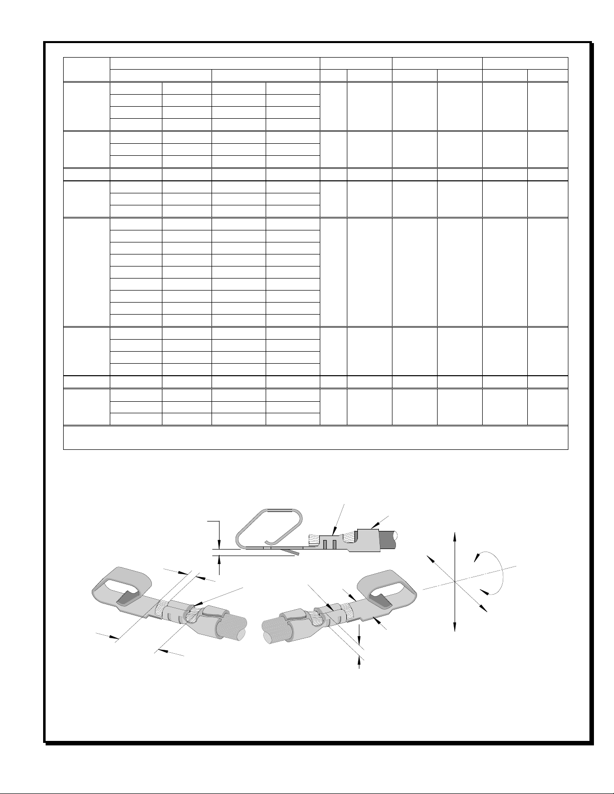
3. Visually inspect the crimped terminal for proper crimp
location.
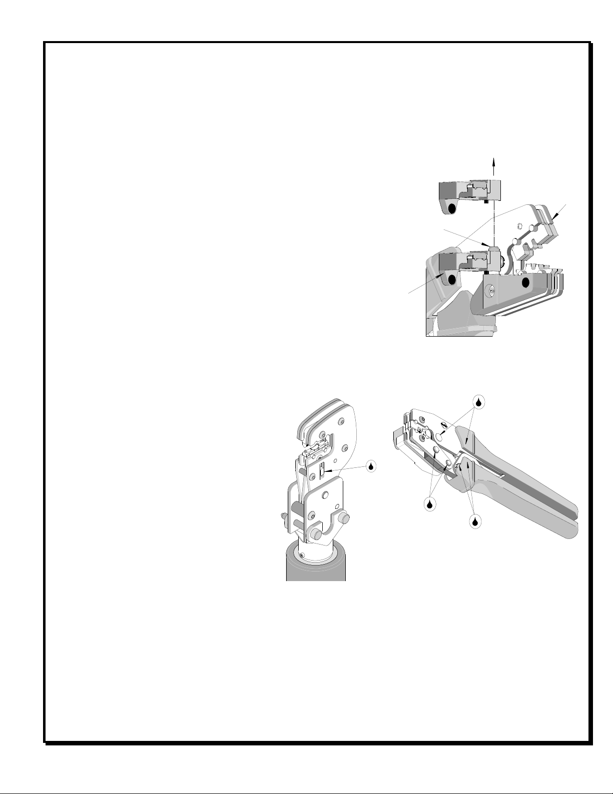
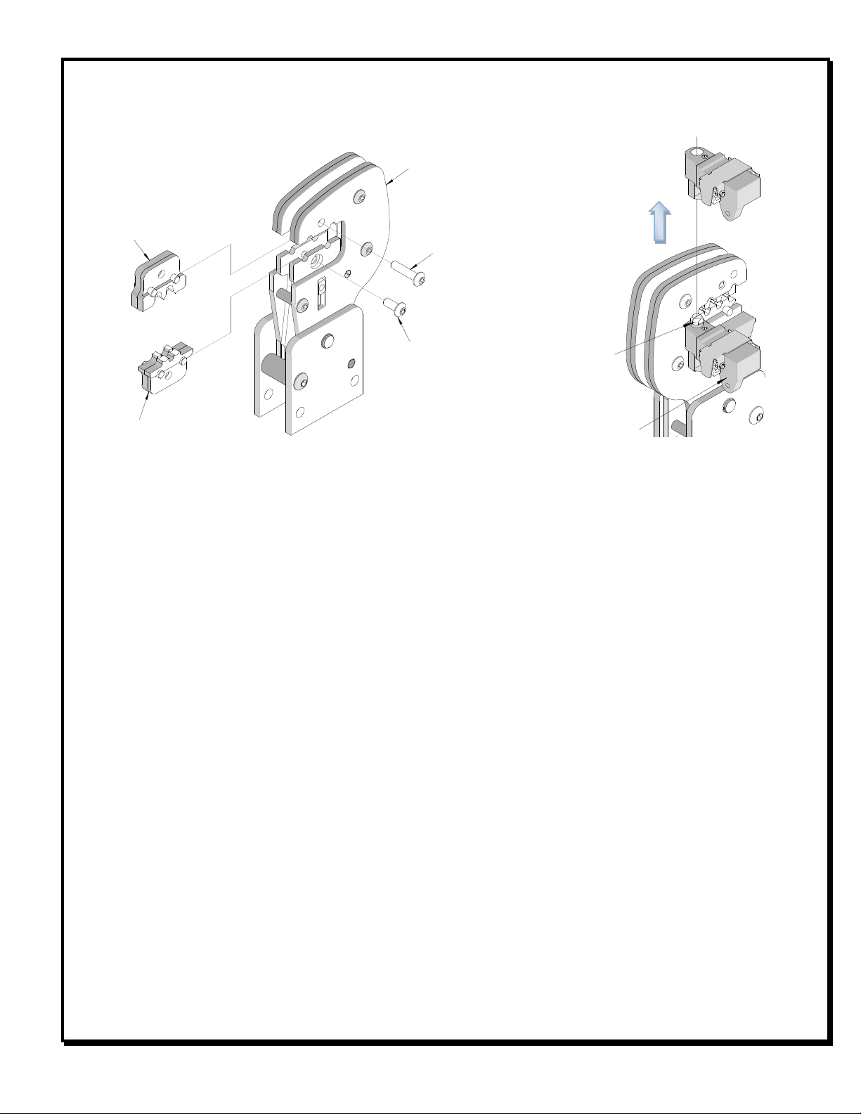
Locator Removal and Installation
1. Open the crimp hand tool.
2. Swing the existing locator open and away from the hand tool.
3. Firmly press down on the brass pivot shaft with your thumb
while pulling up on the locator. Slip the locator off of the top of
the brass pivot shaft. See Figure 5.
4. eplace it with the proper locator by putting it over the brass
pivot shaft and snapping it into place.
Locator Replacement
See the parts list on the last page of this document for the proper
locator order number. Follow the steps above to replace the locator.
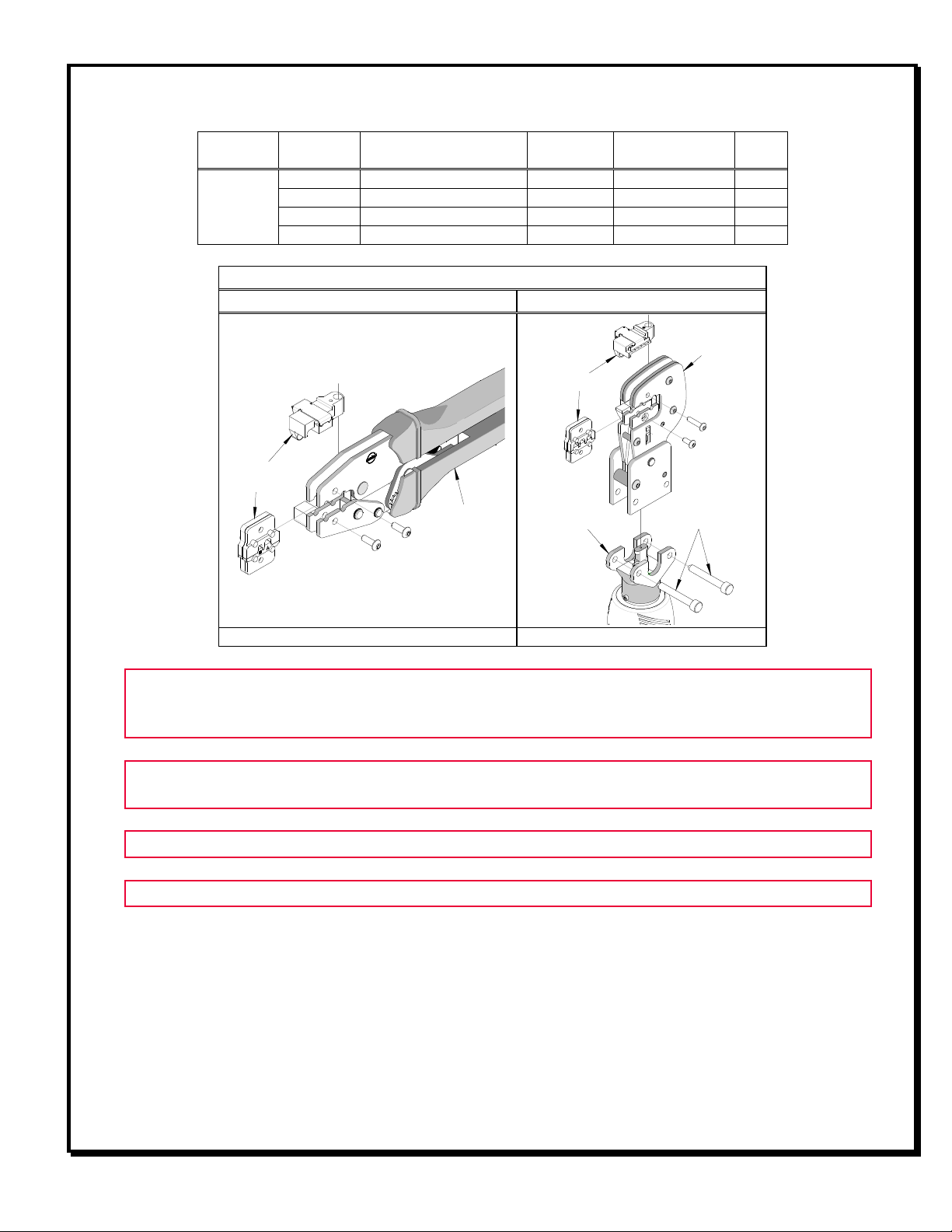
Maintenance
It is recommended that each operator of the
tool be made aware of, and responsible for,
the following maintenance steps:
1. emove dust, moisture and other
contaminants with a clean brush or a soft,
lint-free cloth.
2. Do not use any abrasive materials that
could damage the tool.
3. Make certain all pins, pivot points and
bearing surfaces are protected with a thin
coat of high-quality machine oil. Do not oil
excessively. The tool was engineered for
durability, but like any fine piece of equipment, it needs cleaning and lubrication for a maximum service life of
trouble-free crimping. A 30 weight automotive (light) oil used at the oil points every 5,000 crimps or 3 months
will significantly enhance the tool life. See Figures 6A and 6B.
4. Wipe excess oil from the hand tool, particularly from the crimping area. Oil transferred from the crimping area
onto certain terminations may affect the electrical characteristics of an application.
5. When the tool is not in use, keep the handles closed to prevent objects from becoming lodged in the crimping
dies, and store the tool in a clean, dry area.
LOCATOR
OPEN
ON BRASS PIVOT
SHAFT
LOCATOR
OPEN
Figure 5
Figure 6B
POINTS
(BOTH SIDES)
LIGHT OIL
(EVERY MONTH
OR
5,000 CRIMPS)