Table of contents
1 Document inf1 Document informaormationtion .................................................................................................................................................................................................................................... 55
2 A2 Abbrbbreeviaviationstions .............................................................................................................................................................................................................................................................. 66
3 General3 General................................................................................................................................................................................................................................................................................ 77
4 De4 Devicevice ffeaeatturureses ........................................................................................................................................................................................................................................................ 88
5 Connections5 Connections.................................................................................................................................................................................................................................................................. 99
5.1 Simpli^ed block diagram ........................................................................................................ 9
5.2 Inputs .................................................................................................................................. 11
5.2.1 Arc sensor channels.................................................................................................. 11
5.2.2 inary inputs ............................................................................................................. 11
5.3 Outputs ............................................................................................................................... 12
5.3.1 inary outputs ........................................................................................................... 12
5.3.2 Trip relays.................................................................................................................. 12
5.3.3 System failure relay.................................................................................................... 13
5.4 Auxiliary voltage................................................................................................................... 13
6 Ar6 Arc sensorsc sensors................................................................................................................................................................................................................................................................ 1414
6.1 Arc light ^ber optic loop sensor AQ-06 ................................................................................ 14
6.2 Arc light ^ber optic loop sensor AQ-07 ................................................................................ 14
6.3 Arc light ^ber optic loop sensor AQ-08 ................................................................................ 14
6.4 Sensor dependencies .......................................................................................................... 14
6.5 Connecting sensors............................................................................................................. 15
6.5.1 Fiber loop sensors ..................................................................................................... 15
7 Opera7 Operation and con^gtion and con^guraurationtion .............................................................................................................................................................................................................. 1717
7.1 DIP switch settings .............................................................................................................. 17
7.1.1 Scheme selection ...................................................................................................... 18
7.1.2 Available logic schemes............................................................................................. 18
7.2 Push button (SET) ............................................................................................................... 22
7.2.1 System setup (auto-con^guration) ............................................................................. 23
7.2.2 Reset......................................................................................................................... 23
7.2.3 Input connection check ............................................................................................. 23
7.3 LED indicator functions........................................................................................................ 23
7.4 LED operations guide .......................................................................................................... 24
7.5 Non-volatile memory............................................................................................................ 25
8 S8 Syyststem self-superem self-supervisionvision............................................................................................................................................................................................................................ 2626
9 W9 Wiring exampleiring example...................................................................................................................................................................................................................................................... 2727
10 D10 Dimensions and installaimensions and installationtion ............................................................................................................................................................................................................ 2828
11 T11 Testingesting .......................................................................................................................................................................................................................................................................... 3030
11.1 Testing the light-only mode ................................................................................................ 30
11.2 Testing the light and current mode ..................................................................................... 30
11.3 Testing the operation time.................................................................................................. 31
11.4 Test plan example .............................................................................................................. 31
12 T12 Trroubleshoooubleshootingting................................................................................................................................................................................................................................................ 3333
13 T13 Technicechnical daal datata.................................................................................................................................................................................................................................................... 3434
13.1 Operating times ................................................................................................................. 34
13.2 Auxiliary voltage................................................................................................................. 34
13.3 inary inputs...................................................................................................................... 34
13.4 Trip relays .......................................................................................................................... 34
13.5 inary output(s) ................................................................................................................. 35
13.6 System failure relay............................................................................................................ 35
13.7 Fiber optic loop sensors ..................................................................................................... 35
13.8 Disturbance tests............................................................................................................... 36
13.9 Voltage tests...................................................................................................................... 36
13.10 Mechanical tests.............................................................................................................. 36
13.11 Environmental conditions ................................................................................................. 37
13.12 Casing............................................................................................................................. 37
14 Or14 Ordering infdering informaormationtion ................................................................................................................................................................................................................................ 3838
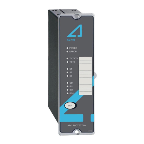
AA -102L-102LVV
Instruction manual
Version: 1.01
© Arcteq Relays Ltd
IM00048
1
