manuals.online logo
Brands
  1. Home
  2. •
  3. Brands
  4. •
  5. Argus Security
  6. •
  7. Security Sensor
  8. •
  9. Argus Security ALTAIR A1000 User manual

Argus Security ALTAIR A1000 User manual

A1000
ANALOGUE PHOTO DETECTOR - ALTAIR SERIES
928b/02
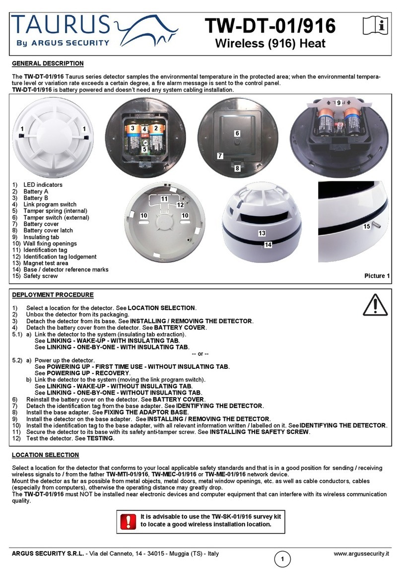
LOOP IN (+)
LOOP IN (-)
LOOP OUT (+)
LOOP OUT (-)
SHIELD
Figure 2
ARGUS SECURITY S.R.L. - Via del Canneto, 14 - 34015 - Muggia (TS) - Italy www.argussecurity.it [email protected] L20-A1000-0001 (vA.5)
GENERAL DESCRIPTION
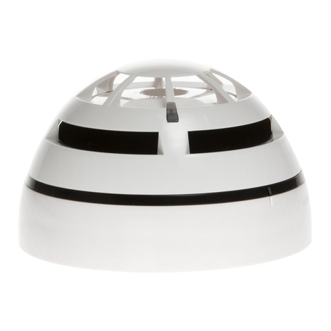
This type of detector (figure 1) continuously samples the air in the protected area to provide the
earliest warning of fire, offering, at the same time, a high level of false alarm rejection.
The particular design of the smoke entry ports limits potential contamination, extends maintenance
periods and does not compromise smoke response sensitivity.
These detectors are designed for an open area protection and must only be connected to control
panels that use the Altair analogue-intelligent addressable communication protocol for monitoring
and control, providing high rates of information exchange and fast and secure responses.
Note: Before installing this device please thoroughly read this leaflet and refer to the applicable
European Standards and National Codes of Practice (e.g. BS5839-1:2002 for UK) for guidance on location, spacing and acceptable
use. Also seek guidance from the compatible control panel instructions to ensure appropriate design criteria and configuration specifi-
cations are followed.
INSTALLATION
For the installation to the ceiling, the detector must be mounted only on the compatible adaptor bases listed in the “TECHNICAL
SPECIFICATIONS” table. Refer to the specific base’s literature for further details.
WIRING
After having installed the base to the ceiling, wiring has to be carried out in order to connect the base to the analogue loop and, so, to
the installation.
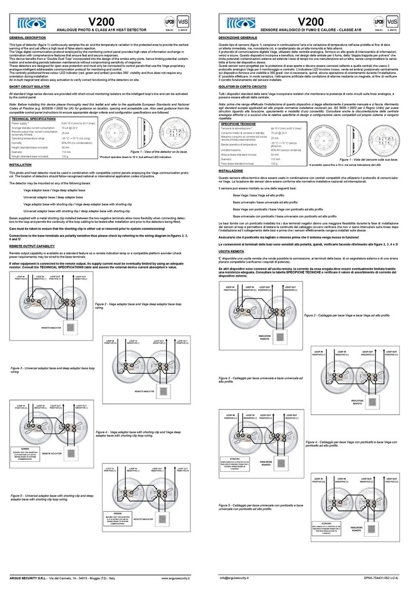
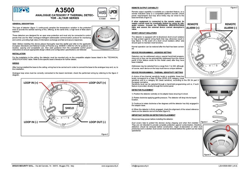
Analogue loop wires must be correctly connected to the base’s terminals: check the performed wiring by referring to the figure 2
diagram.
Figure 1
REMOTE OUTPUT CAPABILITY
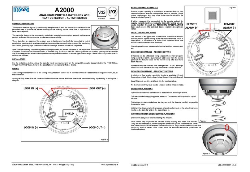
Remote output capability is available as a standard feature, so a
remote indication lamp or a compatible platform sounder (check
power requirements and loop drive limits) may be wired to the
base terminals (Figure 3).
If other equipment is connected to the remote output, its
supply current must be eventually limited by using an ade-
quate resistor. Consult the TECHNICAL SPECIFICATIONS
table and assess the external device current absorption’s
value.
SHORT CIRCUIT ISOLATORS
The detector is equipped with bi-directional short-circuit isolators
to help protect against wiring faults that may otherwise result in
loop failure. In the event of a short circuit isolators either side
should open to maintain most functions.
Normal operation can be restored after the fault has been correct-
ed.
DEVICE PROGRAMMING - ADDRESS SETTING
Detectors can be addressed using a special hand-held program-
ming unit or they can be automatically addressed from the control
panel (if this feature exists for the model used) after they have
been installed.
Addresses may be selected from a range from 1 to 240, although,
of course, each device on the loop must have a unique address.
DEVICE PROGRAMMING - SENSITIVITY SETTING
A choice of four sensitivity levels is available; if such feature is
provided, this level can be set through the control panel.
Level 1 is most sensitive and level 4 is the least sensitive.
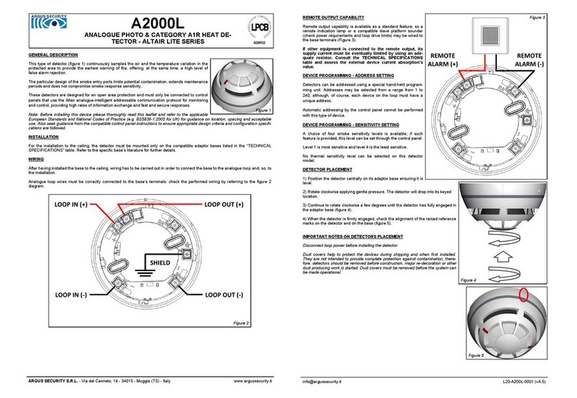
DETECTOR PLACEMENT
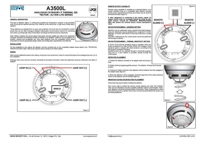
1) Position the detector centrally on its adaptor base ensuring it is level.
2) Rotate clockwise applying gentle pressure. The detector will drop into its keyed
location.
3) Continue to rotate clockwise a few degrees until the detector has fully engaged in
the adaptor base.
4) When the detector is firmly engaged, check the alignment of the raised reference
marks on the detector and on the base (figure 5).
IMPORTANT NOTES ON DETECTORS PLACEMENT
Disconnect loop power before installing the detector.
Dust covers help to protect the devices during shipping and when first installed.
They are not intended to provide complete protection against contamination, there-
fore, detectors should be removed before construction, major re-decoration or other
dust producing work is started. Dust covers must be removed before the system can
be made operational.
Figure 5
Figure 4
REMOTE
ALARM (+)
REMOTE
ALARM (-)
Figure 3
G 213008
ANTI -TAMPER DETECTOR LOCK
The detector can be locked to its base as a deterrent to intentional removal performed by non authorized personnel.
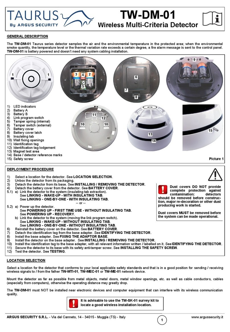
Using a cutter, remove the anti-tamper plastic detail, as illustrated in figure 6.
To unlock the detector, insert the tip of a screwdriver into the side slot of the base by exerting only a light pressure (figure 7), and
release the detector by turning it anticlockwise.
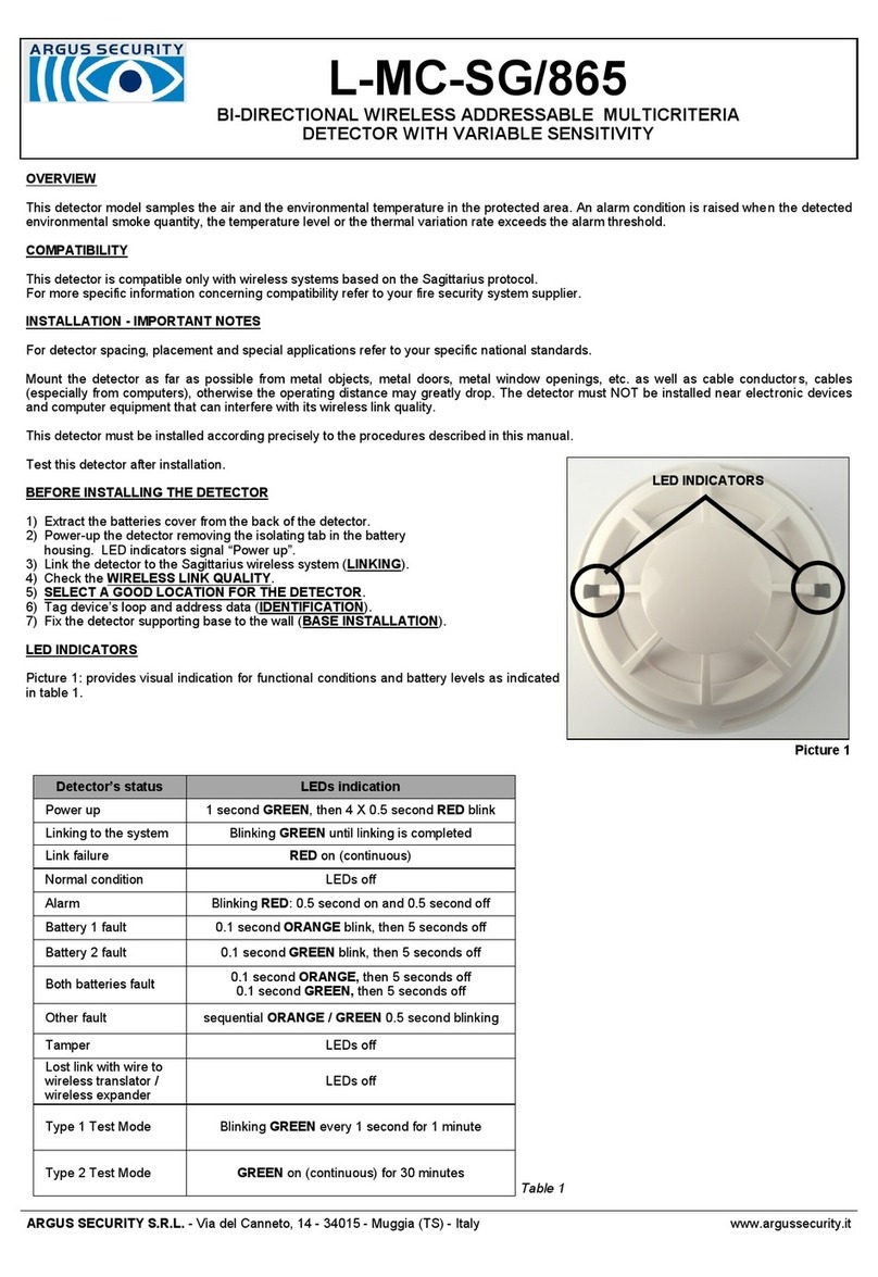
LED INDICATORS
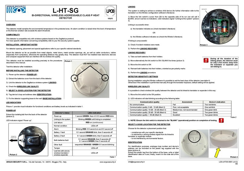
This detector is equipped with dual LEDs that can illuminate Green, Red or Amber to indicate
status condition:
Green: blinking, indicates the normal operative status of the detector.
Red: indicates an alarmed condition of the detector.
Amber: if implemented in panel software, indicates a fault condition of the detector.
LED indicators are managed directly by the control panel and the green blinking can be disabled
by the installer either from the control panel itself or through the programming unit.
Positioning of these LEDs is illustrated in figure 8.
IDENTIFICATION TAB
The adaptor base is equipped with a plastic tab where identification data can be visibly displayed.
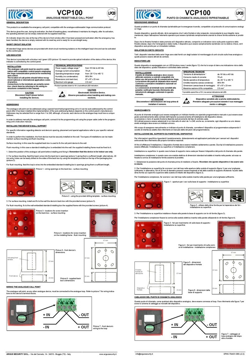
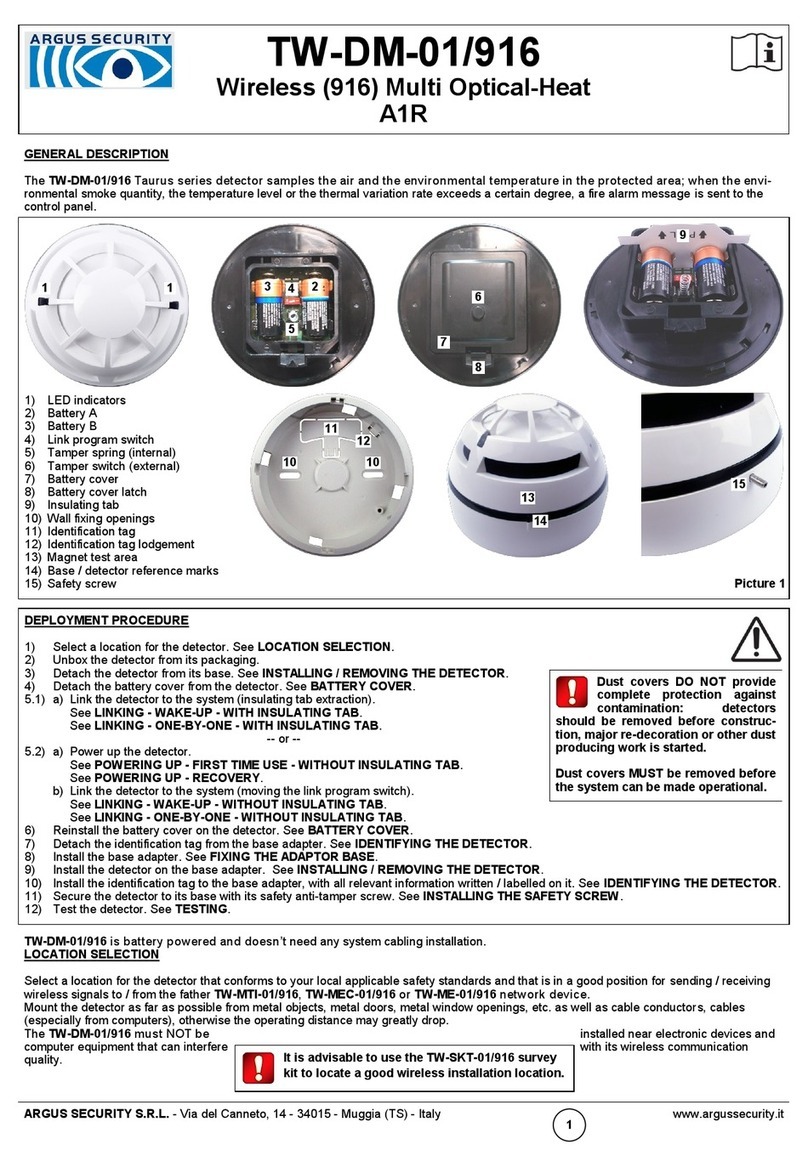
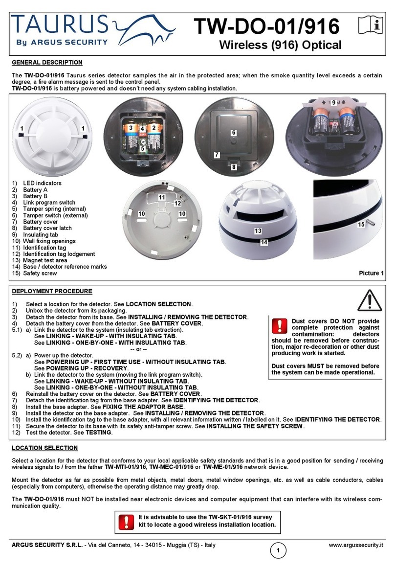
Detach the tab from the base; write or label it with the required information, then insert it into its adaptor base’s slot.
TESTING THE DETECTORS - PRELIMINARY NOTE
Detectors should be tested after installation and during periodic maintenance
visits; it is recommended each device should be tested at least once per year.
After each test reset the system and allow at least one minute for power stabilisa-
tion.
MAGNET TEST
Position the test magnet next to the detector, in correspondence of the raised
mark, then move it 45 degrees anticlockwise (figure 10).
The magnet test simulates smoke in the optical chamber and verifies the function
of all electronic circuits of the detector and its communication with the control
panel. The detector should trigger an alarm message to the control panel, and,
successively, the detector’s red LED should be activated by the control panel
itself.
Figure 7
Figure 10
Figure 8
AEROSOL TEST (SIMULATED SMOKE TEST)
For this test only use test aerosols from an approved manufacturer, in accordance with their application instructions, in order to
prevent contamination or possible damage to the detector. We suggest to spray the aerosol into the detector by using a recommend-
ed applicator. The detector should trigger an alarm message to the control panel, and, successively, the detector’s red LED should
be activated by the control panel itself.
If the detector does not respond to the tests correctly it may be necessary to clean it: in this case follow the instructions indicated in
the “MAINTENANCE” paragraph.
If testing fails again after maintenance then replace the detector with a new one and return the faulty one for servicing.
MAINTENANCE
Before starting any maintenance work, isolate and disable the system in order to avoid accidental and unwanted alarm or fault condi-
tions.
Remove the detector from its mounting base to allow inspection in good light at ground level. Inspect the smoke entry ports around
the detector and use a small, soft bristle brush to dislodge any evident contaminants such as insects, spider webs, hairs, et c. Use a
small vacuum tube or clean, dry and compressed air to suck up or blow away any remaining small particles from the smoke entry
screen area. Wipe the exterior housing of the detector with a clean, damp, lint free cloth to remove any surface film that can later
attract airborne contaminants. Use the hand-held programming unit to read the pollution percentage of the chamber; please, refer to
the programming unit instruction manual.
After all detectors have been inspected, repositioned on their mounting bases and power has been re-applied, check correct opera-
tion by testing the device.
TECHNICAL SPECIFICATIONS **
*Product operates down to 15 V, but without LED indication.
**Check latest version of document TDS-A1000 for further data, obtainable from your supplier.
WARNINGS AND LIMITATIONS
Our devices use high quality electronic components and plastic materials that are highly resistant
to environmental deterioration. However, after 10 years of continuous operation, it is advisable to
replace the devices in order to minimize the risk of reduced performance caused by external
factors. Ensure that this device is only used with compatible control panels. Detection systems
must be checked, serviced and maintained on a regular basis to confirm correct operation.
Smoke detectors may respond differently to various kinds of smoke particles, thus application
advice should be sought for special risks. Detectors cannot respond correctly if barriers exist
between them and the fire location and may be affected by special environmental conditions.
Refer to and follow national codes of practice and other internationally recognized fire engineering
standards.
Appropriate risk assessment should be carried out initially to determine correct design criteria and
updated periodically.
WARRANTY
All devices are supplied with the benefit of a limited 5 years warranty relating to faulty materials or
manufacturing defects, effective from the production date indicated on each product.
This warranty is invalidated by mechanical or electrical damage caused in the field by incorrect
handling or usage.
Product must be returned via your authorized supplier for repair or replacement together with full
information on any problem identified.
Full details on our warranty and product’s returns policy can be obtained upon request.
ARGUS SECURITY S.R.L.
Via del Canneto, 14
34015 Muggia (TS)
Italy
EN 54-7:2018
EN 54-17:2005
A1000
For use in compatible fire detection
and alarm system
Power supply *from 18 V (min) to 40 V (max)
Average standby current consumption 55 uA @ 24 V
Remote output max current consumption (externally limited) 20 mA
Compatible adaptor bases LAB1000 - “Low Profile Adaptor Base”
Operating temperature range -30 °C / +70 °C (no icing)
Humidity 95% RH (no condensation)
IP rating 40 (42 with base’s waterproof protection)
ARGUS SECURITY S.R.L. - Via del Canneto, 14 - 34015 - Muggia (TS) - Italy www.argussecurity.it [email protected] L20-A1000-0001 (vA.5)
Figure 6
Figure 9
2831 0832
12 21
AT5910CPR AT5910UK
This manual suits for next models

1

Other Argus Security Security Sensor manuals

Argus Security Taurus TW-DT-01/916 User manual

Argus Security

Argus Security Taurus TW-DT-01/916 User manual

Argus Security TAURUS TW-MI-S-01/916 User manual

Argus Security

Argus Security TAURUS TW-MI-S-01/916 User manual

Argus Security Taurus TW-SK-01 User manual

Argus Security

Argus Security Taurus TW-SK-01 User manual

Argus Security TAURUS TW-DM-01/BL User manual

Argus Security

Argus Security TAURUS TW-DM-01/BL User manual

Argus Security V100 User manual

Argus Security

Argus Security V100 User manual

Argus Security TAURUS TW-DT-01 User manual

Argus Security

Argus Security TAURUS TW-DT-01 User manual

Argus Security ALTAIR LITE Series User manual

Argus Security

Argus Security ALTAIR LITE Series User manual

Argus Security TAURUS TW-DT-01/BL User manual

Argus Security

Argus Security TAURUS TW-DT-01/BL User manual

Argus Security SG200 User manual

Argus Security

Argus Security SG200 User manual

Argus Security SG200-IS User manual

Argus Security

Argus Security SG200-IS User manual

Argus Security LW-DMCO-01 User manual

Argus Security

Argus Security LW-DMCO-01 User manual

Argus Security A3500 User manual

Argus Security

Argus Security A3500 User manual

Argus Security V200 User manual

Argus Security

Argus Security V200 User manual

Argus Security L-MC-SG User manual

Argus Security

Argus Security L-MC-SG User manual

Argus Security L-HT-SG User manual

Argus Security

Argus Security L-HT-SG User manual

Argus Security A2000L User manual

Argus Security

Argus Security A2000L User manual

Argus Security ALTAIR Series User manual

Argus Security

Argus Security ALTAIR Series User manual

Argus Security Taurus TW-MO-SB-01/916 User manual

Argus Security

Argus Security Taurus TW-MO-SB-01/916 User manual

Argus Security L-HT-SG User manual

Argus Security

Argus Security L-HT-SG User manual

Argus Security Taurus TW-DO-01/916 User manual

Argus Security

Argus Security Taurus TW-DO-01/916 User manual

Argus Security Taurus TW-DM-01 User manual

Argus Security

Argus Security Taurus TW-DM-01 User manual

Argus Security L-OP-SG Operating and maintenance instructions

Argus Security

Argus Security L-OP-SG Operating and maintenance instructions

Argus Security Taurus TW-DT-01/BL User manual

Argus Security

Argus Security Taurus TW-DT-01/BL User manual

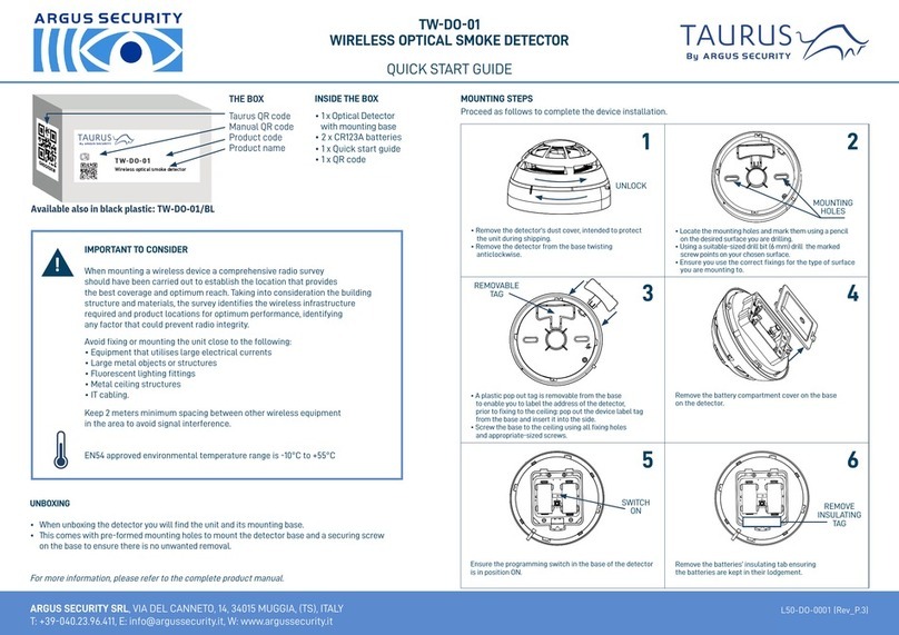
Argus Security L-MC-SG/865 User manual

Argus Security

Argus Security L-MC-SG/865 User manual

Popular Security Sensor manuals by other brands

Burg Wächter MOTION 2010 Assembly and user's manual

Burg Wächter

Burg Wächter MOTION 2010 Assembly and user's manual

Rittal DK 7030.130 Installation and Short User Guide

Rittal

Rittal DK 7030.130 Installation and Short User Guide

ChinaPST PST Series manual

ChinaPST

ChinaPST PST Series manual

MSA V-TEC PFL Instructions for use

MSA

MSA V-TEC PFL Instructions for use

General RLD400 user manual

General

General RLD400 user manual

Meggitt Sensorex 690 043 045 instruction manual

Meggitt

Meggitt Sensorex 690 043 045 instruction manual

Niko Servodan 350-20079 user manual

Niko

Niko Servodan 350-20079 user manual

Carrier SPS installation guide

Carrier

Carrier SPS installation guide

Miller Xenon I283 User instruction manual

Miller

Miller Xenon I283 User instruction manual

Fireye FLAME SIGNATURE SCANNER 1000 manual

Fireye

Fireye FLAME SIGNATURE SCANNER 1000 manual

ESP MAGPRO-HD1 installation instructions

ESP

ESP MAGPRO-HD1 installation instructions

EDS FL - 50 installation manual

EDS

EDS FL - 50 installation manual

TH COMMUNICATIONS DoorProtect user manual

TH COMMUNICATIONS

TH COMMUNICATIONS DoorProtect user manual

SONBEST SM6230M-O2 user manual

SONBEST

SONBEST SM6230M-O2 user manual

Sealey VS0062 instructions

Sealey

Sealey VS0062 instructions

Aereco S-PRE/DAY-NIGHT/T Installation and maintenance  instruction

Aereco

Aereco S-PRE/DAY-NIGHT/T Installation and maintenance instruction

ESYLUX PD-FLAT 360i/6 mini DALI operating instructions

ESYLUX

ESYLUX PD-FLAT 360i/6 mini DALI operating instructions

Kilsen KL710 Installation sheet

Kilsen

Kilsen KL710 Installation sheet

manuals.online logo
manuals.online logoBrands
  • About & Mission
  • Contact us
  • Privacy Policy
  • Terms and Conditions

Copyright 2025 Manuals.Online. All Rights Reserved.