LOCATION SELECTION
Select a location for the module that conforms to your local applicable safety standards and that is in a good position for sending / receiving
wireless signals to / from the father TW-MTI-01/916, TW-MEC-01/916 or TW-ME-01/916 network device.
Mount the module as far as possible from metal objects, metal doors, metal window openings, etc. as well as cable conductors, cables
(especially from computers), otherwise the operating distance may greatly drop.
The TW-MO-SB-01/916 must NOT be installed near electronic devices and computer equipment that can interfere with its wireless
communication quality.
HANDLING THE TOP COVER
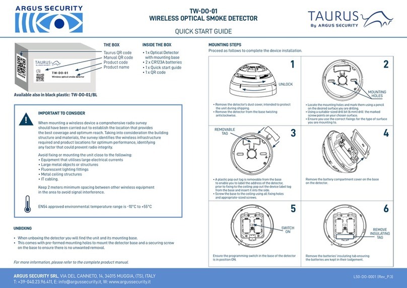
To uninstall the top cover unscrew the four module box’s sealing screws and detach the cover. To install it perform the opposite operation;
take care to seal the module in order to maintain its IP rating.
HANDLING THE PRINTED CIRCUIT BOARD
To uninstall the printed circuit board, remove first the two blocking fixing screws, then carefully extract the board from its box. To reinstall it,
insert its lower side under the two plastic stops, then install the two blocking
screws.
CABLE ENTRY
The module’s box is designed with six M16/20 cable entry knockout holes, distributed on the lateral sides; the two entries above the super-
vised output and relay supervision ports give the best choice. These entries allow sealed, gland fitted output port cables to be connected to
the device and, at the same time, to preserve the original IP protection rating. Fit the cable’s gland (or glands) into the “knocked out” device
box’s cable entries.
WALL INSTALLATION
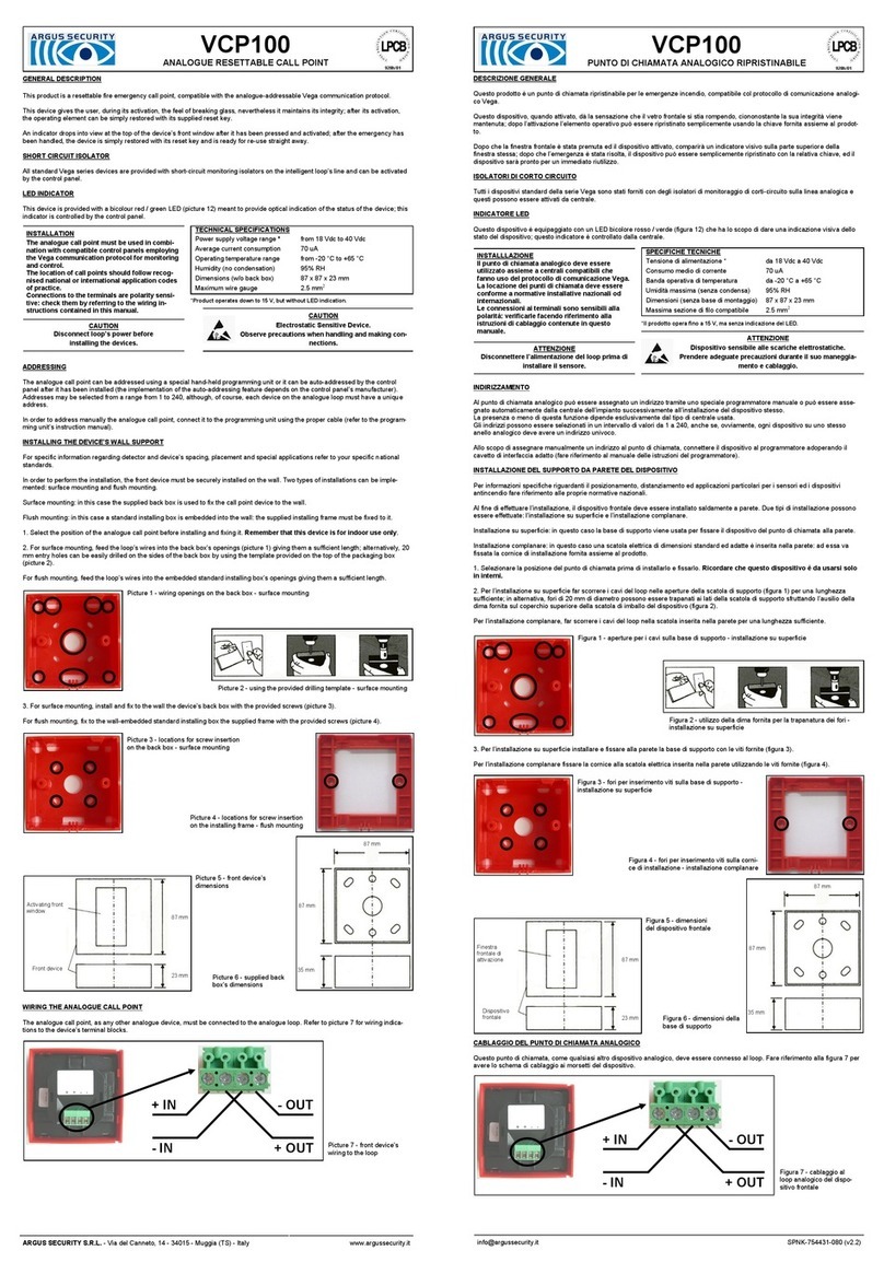
Knockout wall fixing screw openings are indicated in picture 1; these openings,
once knocked out, compromise the IP rating of the
module’s box. Alternatively, you can choose to use the
four IP safe screw holes (picture 1).
WIRING
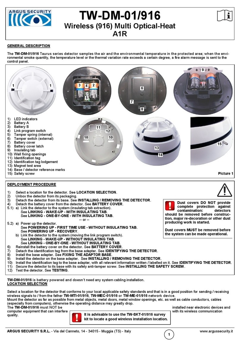
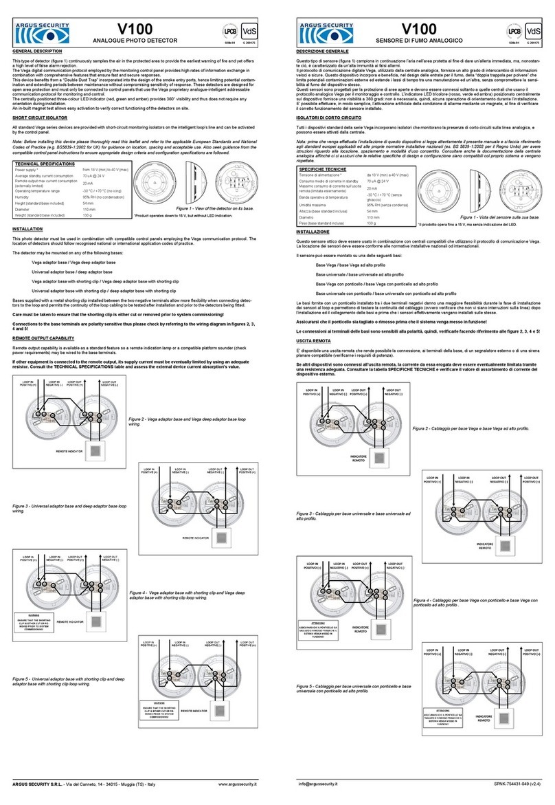
The output line has to be connected either to the super-
vised port (Picture 2) or to the relay port (Picture 3) of the
output module. Use the supervision port to add open and
short circuit system’s surveillance over the relay port.
Make sure to install the REOL resistor at the end of the
supervised output line; if line supervision is not desired,
fit the REOL directly across the supervised output dipole
at the beginning of the line.
BATTERY FAULTS AND BATTERY SUBSTITUTION PROCEDURE
When one or both batteries are low in charge, a specific fault message is routed to the
control panel. If such event occurs:
1) Remove the top cover.
2) Extract both batteries.
3) Insert both new batteries into their holders, correctly oriented.
See POWERING UP - DEVICE LINKED TO THE SYSTEM.
4) Reinstall the top cover.
TESTING
Test the module as follows:
1) Activate the alarm condition.
2) Check the correct activation of the device on the output line.
3) Remove the alarm condition.
2
It is advisable to use the TW-SKT-01/916 survey
kit to locate a good wireless installation location.
To avoid damage, remove the printed circuit
board before knocking out the cable entry holes.
Electrostatic sensitive device: observe precau-
tions when handling the printed circuit board and
making connections.
Picture 2
REOL: 10 KΩ
REOL
External
device
Picture 3
CNO
External
device
V
+
Always install the REOL on the supervised
output and relay supervision ports, even
if they are not used.
Relay port
Ports are polarity
sensitive.
When a low battery condition is indicat-
ed, both batteries must be changed
altogether.
Batteries must be brand new.
Do not touch the Link / program switch.
Ensure that the batteries are installed properly,
with their correct polarities.
Local safety standards may require you
to test these devices on a regular basis.
