2 / 6 P/N 466-2884 (ML) • REV F • ISS 15DEC20
EN: Installation Sheet
Description
ATS1520 Two-way Audio Module is an audio switcher for
Advisor Advanced control panel that is used for audio alarm
verification. The module allows to connect ATS1521 satellites
installed in the protected premises.
Module layout
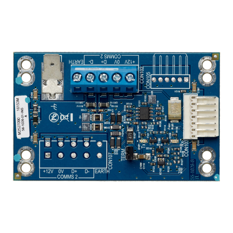
Figure 1: ATS1520 layout
(1) Address jumpers. See “Address jumpers” below.
(2) MI bus connectors.
(3) Power supply jumper. See “Power supply jumper” below.
(4) External power and earthing.
(5) Audio bus.
Jumpers
Address jumpers
Do not use.
The address of the ATS1520 module on the MI-bus is
determined by three jumpers. These jumpers are labelled A0,
A1 and A2. All jumpers must be present (default setting).
Power supply jumper
Power supply jumper defines whether the audio switcher is
powered from MI bus or from an external power supply
connected to the external power terminal (Figure 1, item 4).
MI: ATS1520 is powered from MI bus.
EXT: ATS1520 is powered from an external power supply
(default setting).
Mounting
ATS1520 must be mounted inside ATS panel housing.
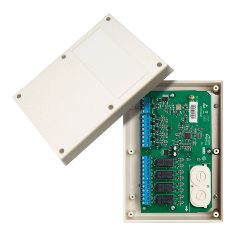
Figure 2 shows an example mounting of the audio module in
Advisor Advanced panels.
WARNING: Electrocution hazard. To avoid personal injury or
death from electrocution, remove all sources of power and
allow stored energy to discharge before installing or removing
equipment.
The installer must have minimum qualifications as follow:
•Basic knowledge of alarm systems and components
•Basic knowledge of electrical wiring and low-voltage
electrical connections
Read this installation sheet and all relevant auxillary
documentation prior to installation.
To mount ATS1520 in an ATS control panel:
1. Place the clips in the square holes. Use fixed metal pillars
where available.
2. Mount ATS1520 using screws and metal washers.
3. Connect the earth terminal to the earth connection of the
housing, if no metal pillars are used.
4. Connect MI bus cable.
5. Mount ATS7700 PSTN Module.
Connection
Connect external power supply to external power terminal
(Figure 1, item 4), if necessary.
Connect audio bus from ATS1521 satellites to audio bus
terminal (Figure 1, item 5). Use eartning connector on external
power and earthing terminal (Figure 1, item 4) to connect audio
bus shield.
The 2-way audio system connection diagram is shown in
Figure 3.
Figure 3: 2-way audio system connection diagram
(1) Audio bus
(2) MI bus
(3) External power supply (optional)
(4) Advisor Advanced system databus
Audio bus
Use twisted pair cable for the audio bus connection (for
example, WCAT52).
Connect audio bus from ATS1521 satellites to the audio bus
terminal (Figure 1, item 5). Use the earthing connector on
external power and the earthing terminal (Figure 1, item 4) to
connect audio bus shield.
Observe the correct polarity and keep the same wires for A+
and A−connectors.
MI bus
Connect the ATS1520 module to the Advisor Advanced panel
using the provided flexible flat cable.
External power supply
Connect an external power supply (or a battery) to the external
power terminal EXT. POWER (Figure 1, item 4) along with the
relevant jumper setting. The ATS1520 module is set as default
to utilize external power supply in order to optimize its
performance for more than one ATS1521 satellite module
connected.
Caution: Special care should be taken while connecting Ext.
Power (+, −) to the battery. Reversing the polarity can cause a
permanent damage of the system.
Specifications
