manuals.online logo
Brands
  1. Home
  2. •
  3. Brands
  4. •
  5. Aritech
  6. •
  7. Control Unit
  8. •
  9. Aritech ATS7340 Assembly instructions

Aritech ATS7340 Assembly instructions

466-5551 (EN) RevD ATS7340 Inst Sheet.pdf
1. Form: A5 double sided printing booklet.
2. Fold to fit in box.
Remark:
Rev.
Date:
Modif. no.
White paper: 75 gr/m, progresso; overprint black.
A
18-02-‘20
D
09-12-‘20
Scale:
Proj.Am
MANUAL, ATS7340
PRINTED SHORT VERSION
466-5551 (EN)
Name:
Mikhail Sleptsov
Date: 09-12-2020
Supers:
Size: A4
Property
of:
Carrier Fire &
Security
Sh. : 110-01
© 2020 Carrier 1 / 4 P/N 466-5551 (EN) • REV D • ISS 09DEC20
ATS7340 4G Module Installation Sheet
EN
1: ATS7340
2: ATSx500A(-IP)-SM
3: ATSx500A(-IP)-MM
EN: Installation Sheet
Description
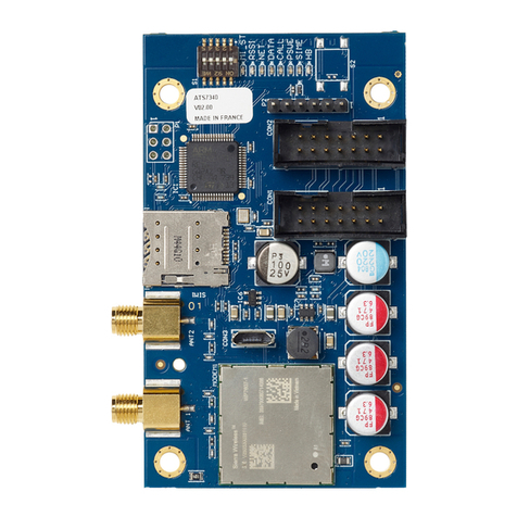
ATS7340 enables alarm reporting via 2G/3G/4G for the
ATSx500A Advisor Advanced panels.
All reporting formats available through PSTN are fully
functional, including voice reporting and audio listen-in. The 4G
module can be used for primary reporting, as well as backup
reporting (using multiple central stations).
ATS7340 can establish a reliable connection for remote
up/downloading to and from the ATS panel.
Important notes
•ATS7340-SIM is an ATS7340 4G module with
a preinstalled UltraSync SIM card. This module and its
SIM card should be used for UltraSync functionality only
when the panel is registered in the UltraSync portal.
Registering the panel in the UltraSync portal is linked to
a monthly service cost.
Carrier reserves the right to check if the Carrier SIM card
is used in the correct modem. Improper use of the modem
or SIM card can result in the product to stop operating with
the UltraSync infrastructure.
ON
1 2 34
(1) (2)
(3)
(4)
(5)
(6)
(7)
5
(4)
(4)
(3)
(3)
(5)
(1)
(1)
(1)
(1)
(4)
RxTx
USB
MI
IP
CON12
CON13
T1
T2
S4 S5
+
+
S1 C
+
S2 CT C
+
+
- - 1 C 2 3 C 4 5 C 6 7 C 8
~~+ -
AC BATT LC-OUTPUTS HC-OUTPUTS SIR TMP AUX POWER INPUTS
CT
+
S3 C
CON16
NTC
COMMS
+12V 0V D+ D-
()2
(4) (4)
(4)
(2)
()5
RxTx
USB
MI
IP
CON12
CON13
T1
T2
S4 S5
+
+
S1 C
+
S2 CT C
+
+
- - 1 C 2 3 C 4 5 C 6 7 C 8
~~+ -
AC BATT LC-OUTPUTS HC-OUTPUTS SIR TMP AUX POWER INPUTS
CT
+
S3 C
CON16
NTC
COMMS
+12V 0VD+ D -
(2)
2 / 4 P/N 466-5551 (EN) • REV D • ISS 09DEC20
•Disable the PIN code request on your SIM card (via any
mobile telephone).
•The product must be used only with the supplied antenna.
•Make sure the antenna itself is placed outside of the
control panel.
•The antenna must be mounted on an appropriate distance
from people, e.g. more than 200 mm.
•For up/downloading via the 4G module use a SIM card
that has data enabled.
•ATS7340 cannot be connected remotely using the
ATS7072 expander kit.
•This device can be installed only by a qualified electrician
or other suitable trained and qualified person.
Caution: Ensure that there is only one GSM/GPRS dialler
(ATS7320, ATS7340, TDA7400, TDA7400NG, or ATS7500)
installed on the MI bus, to avoid any configuration conflicts.
Mounting location
ATS7340 must be mounted inside an ATS panel housing.
WARNINGS
•Disconnect the mains power before opening the cabinet.
Disconnect the AC mains plug from the AC mains wall
socket, or disconnect the mains using the dedicated circuit
breaker.
•Disconnect the battery (when applicable).
Mounting the unit
Figures 2 and 3
(1) Screws
(2) Flat cable
(3) Extension pillars with the plastic rings on existing pillars
(4) Screws on clips
(5) Screws on extension pillars
Mounting ATS7340 into ATSx500A-SM control panels
See Figure 2.
1. Remove the screws (item 1) and lift off the control panel
PCB.
2. Place the extension pillars with the plastic rings on top of
the existing pillars (item 3).
3. Place the clips in the square holes (item 4).
4. Mount ATS7340 using the screws and extension pillars
(item 5).
5. Place the ATS control panel PCB back into its original
position.
Mounting ATS7340 into ATSx500A-MM control panels
See Figure 3.
1. Place the clips in the square holes (item 4). Use metal
pillars when available.
2. Mount ATS7340 using screws.
Connecting the 4G module
WARNING: Disconnect the AC mains plug from the AC mains
wall socket.
1. Connect the flat cable (item 2 in Figures 2 and 3) between
the control panel (MI connector) and ATS7340 (connector
CON2 or CON3).
2. Connect the antenna to the 4G module.
Note: Use the antenna provided with the module to get
the best signal strength.
3. Insert the SIM module into the SIM socket (SIM).
4. Apply power to the control panel and to the 4G module.
5. Check the field strength (RSSI LED). When required,
move the antenna in order to get the best signal.
Operating instructions
Refer to ATSx500A Advisor Advanced Installation and
Programming Manual for details on:
•Operating instructions for all functionalities
•Available keys, codes, and related details
•User programmable functions
Testing the 4G module
To check the correct reporting to the Central Station, we
recommend you to create an event (for example, a test call, an
opening, or a closing event), and to ensure that the Central
Station receives this event successfully.
Description of the ATS7340
Figure 1
Item
Description
Function
(1)
DIP switch
See Table 1 below.
(2)
LEDs
Status LEDs.
(3), (4)
CON3, CON2
MI bus, system connector. Connects to
the ATS panel.
(5)
SIM
SIM socket. Holds GSM micro-SIM card.
(6)
ANT2
Do not use.
(7)
ANT1
SMA antenna connector.
DIP switch
The DIP switch provides the functionality described in Table 1
below.
Table 1: DIP switch description
No.
Name
Function
Default value
1.
TEST
Factory test mode
Off
2.
Reserved
Off
3.
FU
Firmware upgrade
Off
4.
MFU
Modem firmware upgrade
Off
5.
Reserved
Off
P/N 466-5551 (EN) • REV D • ISS 09DEC20 3 / 4
LEDs
In the following LED descriptions, a flash is defined as 250 ms
on and 250 ms off. Groups of flashes are separated by 1 s off.
MI_ST (D1)
The MI_ST LED (green) displays the status of the
communication interface to the panel.
Table 2: MI_ST LED status
Duty cycle
Rate (±10%)
Description
100%
—
Power on (in case none of the cases
below are valid)
0%
—
No power or power failure
25%
1 s
Initialization OK, waiting for
communication
50%
1 s
Everything OK, communication running
75%
500 ms
Hardware failure
50%
250 ms
Failure in communication, waiting for
reinitialization
RSSI (D2)
The RSSI LED (green) indicates the field strength or signal
strength found by the 4G module. The number of flashes
indicates the level.
Table 3: RSSI LED status
Flashes
Description
Off
No field strength (no network detected)
1 to 5
Field strength indication from poor (1) to excellent (5)
NET (D3)
The NET LED (green) indicates the status of the network. The
meaning of the number of flashes is described in Table 4
below.
Table 4: NET LED status
Flashes
Description
Off
Not registered
On
Registered to home network
1
Registered to roaming network
2
Searching network
3
Denied
4
Unknown
DATA (D4)
The DATA LED (green) indicates the status of the GPRS/LTE
communication.
Table 5: DATA LED status
State
Description
Off
GPRS/LTE is not available
On
GPRS/LTE is available, connection established
Blink
GPRS/LTE is available, connection established, sending data
Flash
GPRS/LTE is available, connection not established
CALL (D5)
The CALL LED (yellow) indicates status of the audio
information transmitted to the central station.
Table 6: CALL LED status
Duty cycle
Rate (±10%)
Description
100%
—
Connected
0%
—
Offline
10%
1 s
Connecting
50%
1 s
Ringing present
PSUE (D6)
The PSUE LED (red) indicates the status of the power supply.
Table 7: PSUE LED status
Duty cycle
Rate (±10%)
Description
Off
—
Power supply okay
50%
1 s
MI bus voltage low
On
—
Power supply problem
SIME (D7)
The SIME LED (red) indicates the status of the SIM card. The
meaning of the number of flashes is indicated in Table 8 below.
Table 8: SIME LED status
Flashes
Description
Off
Ready
1
PIN error
2
PUK error
3
PIN 2 error
4
PUK 2 error
5
SIM blocked from network
On
SIM not present
HB (D8)
The HB LED (red) indicates that the device is running.
Table 9: HB LED status
Duty cycle
Rate (±10%)
Description
Off
—
ATS7340 is not operational
50%
1 s
ATS7340 is running
On
—
ATS7340 is not operational
Alarm transmission requirements
All 4G module faults are logged in the control panel and
indicated by the fault LED and corresponding fault messages
on the keypad display.
The transmission between appropriate central stations and the
4G module is constantly monitored by sending presence
(heartbeat) messages to central station receivers.
Advisor Advanced ATSx500A
To program the required polling time in Advisor Advanced
ATSx500A, go to menu “Heartbeat time” and set a value from
every second (00:00’01) to every day (23:59’59).
4 / 4 P/N 466-5551 (EN) • REV D • ISS 09DEC20
In case of the dual path reporting, if the primary CS
communication fails, the backup CS heartbeat time is switched
from normal to frequent according to a value configured in the
menu “Frequent HB time”.
For programming details, see Advisor Advanced Installation
and Programming Manual. The required settings for each ATS
category are listed in Chapter “Regulations”, section
“Transmitter polling interval requirements”.
Substitution and information security
•Triple-DES, Symmetric encryption algorithms are used
with key length 192 bits.
•In case hash functions are used, they give a minimum of
128 bits output.
•Regular automatic key changes are used with machine
generated randomized keys.
Specifications
Compatibility
ATSx500A Advisor Advanced control
panel with firmware version MR4.4 or
later
Power supply (via ribbon
cable from control panel
9 to 14 V฀
Current consumption (at 13.8 V฀±5%):
MI bus (standby)
<100 mA
MI bus (GSM online)
120 mA
MI bus (2G/3G/4G max.)
200 mA
Wireless operating frequency
703–748 MHz (B28)
832–862 MHz (B20)
880–915 MHz (B8, E-GSM 900)
1710–1785 MHz (B3, DCS 1800)
1920–1980 MHz (B1)
2500–2570 MHz (B7)
Maximum power output:
703–748 MHz, 832–862 MHz,
1920–1980 MHz, 2500–
2570 MHz
Class 3bis (23 dBm)
1710–1785 MHz
Class 1 (30 dBm)
880–915 MHz
Class 4 (33 dBm)
Dimensions
86.5 x 50.0 mm
Battery type and max.
capacity
See the appropriate control panel
installation manual
Weight
35 g
Temperature
−10 to +55°C
Relative humidity
<95% noncondensing
Serviceable parts
There are no serviceable parts in
ATS7340
SPT type
EN 50131-10:2014 Type Y
Regulatory information
Manufacturer
Carrier Fire & Security Americas Corporation, Inc.
13995 Pasteur Blvd
Palm Beach Gardens, FL 33418, USA
Authorized EU manufacturing representative:
Carrier Fire & Security B.V.
Kelvinstraat 7, 6003 DH Weert, Netherlands
Product warnings
and disclaimers
THESE PRODUCTS ARE INTENDED FOR SALE
TO AND INSTALLATION BY QUALIFIED
PROFESSIONALS. CARRIER FIRE &
SECURITY CANNOT PROVIDE ANY
ASSURANCE THAT ANY PERSON OR ENTITY
BUYING ITS PRODUCTS, INCLUDING ANY
“AUTHORIZED DEALER” OR “AUTHORIZED
RESELLER”, IS PROPERLY TRAINED OR
EXPERIENCED TO CORRECTLY INSTALL FIRE
AND SECURITY RELATED PRODUCTS.
For more information on warranty disclaimers and
product safety information, please check
https://firesecurityproducts.com/policy/product-
warning/ or scan the QR code.
Certification
This product was tested and certified to
EN 50136-2:2013 for Alarm transmission system
performance SP3 for reporting over GPRS to the
OH Receiver.
This product was tested and certified to
EN 50136-2:2013 for Alarm transmission system
performance SP4 for reporting over GPRS to the
OH Receiver.
This product was tested and certified to
EN 50136-2:2013 for Alarm transmission system
performance DP2 for backup reporting over
GPRS to the OH Receiver.
This product was tested and certified to
EN 50136-2:2013 for Alarm transmission system
performance DP3 for backup reporting over
GPRS to the OH Receiver.
Tested and certified by Telefication B.V.
Alarm transmission class: Pass-through operation
mode.
Carrier Fire & Security hereby declares that this
device is in compliance with the applicable
requirements and provisions of all applicable rules
and regulations, including but not limited to the
Directive 2014/53/EU. For more information see:
firesecurityproducts.com
REACH
Product may contain substances that are also
Candidate List substances in a concentration
above 0.1% w/w, per the most recently published
Candidate List found at ECHA Web site.
Safe use information can be found at
https://firesecurityproducts.com/en/content/intrusi
on-intro
2012/19/EU (WEEE directive): Products marked
with this symbol cannot be disposed of as
unsorted municipal waste in the European Union.
For proper recycling, return this product to your
local supplier upon the purchase of equivalent
new equipment, or dispose of it at designated
collection points. For more information see:
recyclethis.info
Product
documentation
Please consult the following web link to retrieve
the electronic version of the product
documentation.
This link will guide you to the EMEA regional
contact page. On this page you can request your
login to the secured web portal where all manuals
are stored.
https://firesecurityproducts.com/en/contact
Contact information
firesecurityproducts.com or www.aritech.com

Other manuals for ATS7340

1

Other Aritech Control Unit manuals

Aritech ATS1520 Assembly instructions

Aritech

Aritech ATS1520 Assembly instructions

Aritech ATS7340 Assembly instructions

Aritech

Aritech ATS7340 Assembly instructions

Aritech IU2050C Assembly instructions

Aritech

Aritech IU2050C Assembly instructions

Aritech ATS670 Assembly instructions

Aritech

Aritech ATS670 Assembly instructions

Aritech IO2034NC Assembly instructions

Aritech

Aritech IO2034NC Assembly instructions

Aritech ATS7200N Assembly instructions

Aritech

Aritech ATS7200N Assembly instructions

Aritech ATS608 Assembly instructions

Aritech

Aritech ATS608 Assembly instructions

Aritech IU2050NC Assembly instructions

Aritech

Aritech IU2050NC Assembly instructions

Aritech ACA 001 Assembly instructions

Aritech

Aritech ACA 001 Assembly instructions

Aritech ISM-95 Assembly instructions

Aritech

Aritech ISM-95 Assembly instructions

Aritech VDS2000 Ferrite Assembly instructions

Aritech

Aritech VDS2000 Ferrite Assembly instructions

Aritech ATS7200 User manual

Aritech

Aritech ATS7200 User manual

Popular Control Unit manuals by other brands

Festo MS6-SV Series operating instructions

Festo

Festo MS6-SV Series operating instructions

LIAG Venturi operating manual

LIAG

LIAG Venturi operating manual

Theben EM LAN top2 quick start guide

Theben

Theben EM LAN top2 quick start guide

LumenRadio W-Modbus manual

LumenRadio

LumenRadio W-Modbus manual

Festo CTEU-EP Original instructions

Festo

Festo CTEU-EP Original instructions

Applied Motion Products ST10-S Hardware manual

Applied Motion Products

Applied Motion Products ST10-S Hardware manual

Huber Pilot ONE manual

Huber

Huber Pilot ONE manual

Sames GNM 100 user manual

Sames

Sames GNM 100 user manual

Thyracont VD9 operating instructions

Thyracont

Thyracont VD9 operating instructions

Simplex 4100-6065 installation instructions

Simplex

Simplex 4100-6065 installation instructions

AsahiAV H-V074-E user manual

AsahiAV

AsahiAV H-V074-E user manual

TPA TRS67-16I Documentation

TPA

TPA TRS67-16I Documentation

FrSky R9M 2019 LBT instruction manual

FrSky

FrSky R9M 2019 LBT instruction manual

Allen-Bradley Bulletin 160 DeviceNet user manual

Allen-Bradley

Allen-Bradley Bulletin 160 DeviceNet user manual

Bray 950 Series Installation, operation and maintenance manual

Bray

Bray 950 Series Installation, operation and maintenance manual

Bentel Security OmniaMOD-V2 Installation and use manual

Bentel Security

Bentel Security OmniaMOD-V2 Installation and use manual

IFM Electronic Efector 500 operating instructions

IFM Electronic

IFM Electronic Efector 500 operating instructions

Bastl Sense user manual

Bastl

Bastl Sense user manual

manuals.online logo
manuals.online logoBrands
  • About & Mission
  • Contact us
  • Privacy Policy
  • Terms and Conditions

Copyright 2025 Manuals.Online. All Rights Reserved.