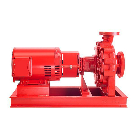
Intelligent Variable Speed Booster Systems: Basic Operating Function
Every Armstrong Intelligent Variable Speed (IVS)
Packaged System – regardless of size or horse power
rating – incorporates the twelve (12) basic operating
functions as follows:
1. For Continous Run and Intermittent Systems - Sequential
starting and stopping of the pumps is achieved by a
combination of pump speed, power and set point
pressure. A set point pressure control will bring on a lag
pump if the lead pump(s) are operating at full speed and
not maintaining set point pressure. When the lead pump
reaches 100% speed or maximum motor nameplate
power and the system pressure is not being satisfied, the
second pump (lag pump) is automatically started. When
a lag pump is started up, a timeclock in the pump
controller keeps it operating for a minimum of a 1 minute
period to prevent the pump from cycling on and off. On a
three, four or five pump system, the third, fourth and fifth
pumps are brought on in the same way when the
combined pumps reach 100% speed or maximum motor
nameplate power and the system pressure is not being
satisfied. A similar sequence of events takes place in
reverse on decreasing demand.
2. Pump RPM is controlled by a Variable Frequency
Drive (VFD) connected directy to each individual
pump motor. An analog signal from the discharge
pressure transmitter is compared to a desired set
point entered in to the operator panel. The pump
logic controller then instructs the VFD to either speed
up or slow down in order to meet or maintain the
system set point pressure.
3. A low suction pressure or level shutdown alarm is
included with every system to protect the pumps from
a loss of suction pressure or water supply. If the water
supply pressure, as measured by the suction pressure
transmitter falls to 5 psi or the tank level switch
(supplied by other) sends a signal to the panel, the
pump controller will prevent the pumps from running.
This condition is indicated by a "low suction pressure"
or "low suction level" alarm description on the control
panel alarm page.
4. Variable speed plumbing booster systems come with
the following standard alarm functions in addition to the
Low Suction Pressure/Level Protection;
-High Suction Pressure Shutdown
-Low Suction Pressure Shutdown
-High System Pressure Shutdown
-Low System Pressure Shutdown
5. Should a motor or drive overload and fail to operate,
the next pump in sequence starts up automatically.
6. Lead Pump status is alternated after every 24 hrs of
operation, as a default. The first pump placed in the
auto position is considered the lead pump. HOA
switches are located in the individual pump control
screens. Alternation includes all duty and optional
standby pumps.
7. No-flow shut down is achieved through drive
parameter control and pressure monitoring. Once a
no-demand condition is achieved for a period of 5
minute, the controller will increase the pump speed
and charge the drawdown tank or system an
additional 5 psi before shutting down.
8. A 15 second delay is incorporated in every system
restart. Once started, the pumps ramp up to meet the
required set point pressure.
9. The Soft Fill Mode is enabled when the booster
system is first powered and after any power disruption.
Once started, the pumps ramp up slowly to meet the
Soft Fill set point pressure or after a 5 minute
operational period and return to normal operation.
10. The Pressure Setback Mode is enabled as standard.
The system pressure set point is reduced linearly, as
a percentage, as flow decreases.
11. When the Emergency Power Mode is enabled and upon
receiving an Emergency Power digital signal, power and
control will be restricted to the lead pump only, the Low
System Pressure Shutdown will be disabled and the
Emergency Power Low System Pressure alarm will be
enabled. The one pump will operate for the duration of
the Emergency Power Mode and the system will switch
to Normal Mode when a signal is not present and the
minimum run timer has expired.
12. Variable Speed Controllers are supplied with up to 7
Normally Open (NO) dry contacts for remote
monitoring. The contacts are located on the upper left
hand portion of the pump controller and indicate the
following conditions:
1, 2 – Discharge Pressure Sensor
3, 4 – Suction Pressure Sensor
5, 6 – Remote Start
7, 8 – Level Switch 1 (Signal by Other)
9, 10 – Emergency Power (Signal by Other)
11, 12 – System Alarm
13, 14 – Pump Running
1+ 3+ 5+ 7+ 9+ 11+ 13+
2- 4- 6- 8- 10- 12- 14-
Communication Option
(Serial connection except for BACnet (IP/ENET))
15, 16 – BAS Communication
17, 18 – BAS/VFD Ground
19, 20 – VFD Communication
15+ 17+ 19+
16- 18- 20-
Page 5 of 34


