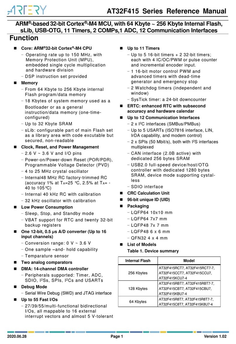
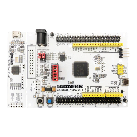
ARTERY AT32 Installation and operating instructions

AT32 Printf Debug Demo
2019.08.05 1 Rev 1.0.2
www.arterytek.com
AN0015
Application Note
AT32 Printf Debug Demo
Introduction
It is common for the user to check the debug process information in the process of application code
debug. In most cases, this action can be done through the serial port debugging assistant.
However, it would be a headache for users to try to observe the testing process information when
the serial port assistant is not supported by the hardware.
To address the above concerns, this application note provides a complete set of example codes
describing how to output the debug process information, especially when the serial port debugging
assistant is not available.
Applicable products:
Part number
AT32F403xx
AT32F413xx
AT32F415xx
AT32F403Axx
AT32F407xx

AT32 Printf Debug Demo
2019.08.05 2 Rev 1.0.2
www.arterytek.com
Contents
1Overview................................................................................................................. 6
2Detailed information.............................................................................................. 7
2.1 Printf via Terminal I/O in IAR..................................................................................... 7
2.1.1 Introduction...................................................................................................................7
2.1.2 Example code...............................................................................................................7
2.1.3 Environment and hardware..........................................................................................7
2.1.4 Software .......................................................................................................................7
2.1.5 Debug and download...................................................................................................7
2.2 Redirect Printf as serial ports in IAR.........................................................................9
2.2.1 Introduction...................................................................................................................9
2.2.2 Example code...............................................................................................................9
2.2.3 Environment and hardware..........................................................................................9
2.2.4 Software .....................................................................................................................10
2.2.5 Debug and download.................................................................................................10
2.3 Printf via Debug (printf) Viewer in Keil.....................................................................11
2.3.1 Introduction.................................................................................................................11
2.3.2 Example code.............................................................................................................11
2.3.3 Environment and hardware........................................................................................11
2.3.4 Software .....................................................................................................................11
2.3.5 Debug and download.................................................................................................12
2.4 Redirect Printf as serial ports in Keil (using MicroLIB)............................................14
2.4.1 Introduction.................................................................................................................14
2.4.2 Example code.............................................................................................................14
2.4.3 Environment and hardware........................................................................................14
2.4.4 Software .....................................................................................................................15
2.4.5 Debug and download.................................................................................................15
2.5 Redirect Printf as serial ports in Keil (not use MicroLIB)......................................... 17
2.5.1 Introduction.................................................................................................................17
2.5.2 Example code.............................................................................................................17
2.5.3 Environment and hardware........................................................................................17
2.5.4 Software .....................................................................................................................18
AT32 Printf Debug Demo
2019.08.05 3 Rev 1.0.2
www.arterytek.com
2.5.5 Debug and download.................................................................................................19
2.6 Printf via JLinkRTT................................................................................................. 20
2.6.1 Introduction.................................................................................................................20
2.6.2 Example code.............................................................................................................20
2.6.3 Environment and hardware........................................................................................20
2.6.4 Software .....................................................................................................................20
2.6.5 Debug and download.................................................................................................21
3Notes..................................................................................................................... 24
4Revision history................................................................................................... 25

AT32 Printf Debug Demo
2019.08.05 4 Rev 1.0.2
www.arterytek.com
List of tables
Table 1. AT MCUs printf function use methods....................................................................................6
Table 2. Hardware connection table--(without JTDO).........................................................................7
Table 3. Hardware connection table -- (without JTDO).......................................................................9
Table 4. Hardware connection table--(USART)...................................................................................9
Table 5. Hardware connection table--(with JTDO)............................................................................ 11
Table 6. Hardware connection table--(without JTDO).......................................................................14
Table 7. Hardware connection table -- (USART)...............................................................................14
Table 8. Hardware connection table -- (without JTDO).....................................................................17
Table 9. Hardware connection table--(USART).................................................................................17
Table 10. Hardware connection table -- (without JTDO)...................................................................20
Table 11. Document revision history..................................................................................................25

AT32 Printf Debug Demo
2019.08.05 5 Rev 1.0.2
www.arterytek.com
List of figures
Figure 1. Virtual terminal window path ................................................................................................8
Figure 2. Virtual terminal interaction window.......................................................................................8
Figure 3. Serial port debugging assistant window.............................................................................10
Figure 4. Keil virtual terminal window path........................................................................................12
Figure 5. Keil virtual terminal interaction window..............................................................................13
Figure 6. MicroLIB settings................................................................................................................15
Figure 7. Serial port interaction window............................................................................................16
Figure 8. MicroLIB settings................................................................................................................18
Figure 9. Serial port interaction window............................................................................................19
Figure 10. Code debug......................................................................................................................21
Figure 11. JLinkRTTClient window output information......................................................................22
Figure 12. JLinkRTTViewer window..................................................................................................22
Figure 13. Device selection window..................................................................................................23
Figure 14. JLinkRTTViewer window output information....................................................................23

AT32 Printf Debug Demo
2019.08.05 6 Rev 1.0.2
www.arterytek.com
1 Overview
This application note describes how to use the printf function of AT chips in the environment of Keil
and IAR. There are five methods to be listed in the table below, with each of them being detailed in
this document.
Table 1. AT MCUs printf function use methods
AT MCUs printf function use methods
No.
Environment
Description
Remark
Method 1
IAR
Printf via Terminal I/O.
See 3.1
Method 2
Redirect Printf as serial ports.
See 3.2
Method 3
Keil
Printf via Debug (printf) Viewer.
See 3.3
Method 4
Redirect Printf as serial ports (using MicroLIB)
See 3.4
Method 5
Redirect Printf as serial ports( not use MicroLIB)
See 3.5
Method 6
IAR/Keil
Printf via JLinkRTTClient window.
See 3.6

AT32 Printf Debug Demo
2019.08.05 7 Rev 1.0.2
www.arterytek.com
2 Detailed information
2.1 Printf via Terminal I/O in IAR
2.1.1 Introduction
The IAR driver linked to the Terminal contains standard input and output driver functions such as
scanf and printf so that the information interaction of the project files can be done via the Terminal
I/O.
2.1.2 Example code
001_Printf_Test_IAR_Terminal\USER
2.1.3 Environment and hardware
2.1.3.1 Development environment
This method is used in the IAR environment. The compiling environment used in the example code
is IAR_V6/7/8 with the hardware board AT-START-F403_V1.2.
2.1.3.2 Hardware connection
J-Link/AT-Link&... connection
Table 2. Hardware connection table--(without JTDO)
Hardware connection table--(without JTDO)
No.
AT-START-F403_V1.2
J-Link/AT-Link&…
Attention
1
3.3V
3.3V
None
2
PA13
SWDIO
Must Pull up external
3
PA14
SWCLK
Must Pull down external
4
NRST
RSTn
None
5
GND
GND
None
2.1.4 Software
2.1.4.1 Header file
Add the stdio.h to the code project files.
2.1.4.2 Redirection settings
Unlock the redirection of Printf (Shield the Printf from the actual serial interface)
2.1.5 Debug and download
Compile the code and download to the MCU, then enter the debug environment to call up the
virtual terminal through View -> Terminal I/O, and run the code at full speed, then the “Hello World”
is visible in the Output column (Figure 2), and the data in the Input column is also displayed in this

AT32 Printf Debug Demo
2019.08.05 9 Rev 1.0.2
www.arterytek.com
2.2 Redirect Printf as serial ports in IAR
2.2.1 Introduction
Redirect the Printf function to a set of actual serial ports in the chip, and output via TX pin and
finally implement information interaction through the serial port debugging assistant.
2.2.2 Example code
002_Printf_Test_IAR_USART2\USER
2.2.3 Environment and hardware
2.2.3.1 Development environment
This method is used in the IAR environment. The compiling environment used in the example code
is IAR_V6/7/8 with the hardware board AT-START-F403_V1.2.
2.2.3.2 Hardware connection
2.2.3.2.1 J-Link/AT-Link&... connection
J-Link/AT-Link&... connection
Table 3. Hardware connection table -- (without JTDO)
Hardware connection table--(without JTDO)
No.
AT-START-F403_V1.2
J-Link/AT-Link&…
Attention
1
3.3V
3.3V
None
2
PA13
SWDIO
Must Pull up external
3
PA14
SWCLK
Must Pull down external
4
NRST
RSTn
None
5
GND
GND
None
2.2.3.2.2 USART2 connection
Table 4. Hardware connection table--(USART)
hardware connection table--(USART)
序号
AT-START-F403_V1.2
USB_To_TTL(CH340)
Attention
1
GND
GMD
None
2
PA2
RXD
None
3
PA3
TXD
None

AT32 Printf Debug Demo
2019.08.05 10 Rev 1.0.2
www.arterytek.com
2.2.4 Software
2.2.4.1 Header files
Add the “stdio.h”to the code project files.
2.2.4.2 Redirection settings
Initialize the serial ports and redirect the Printf function to the actual serial ports. The redirection
function is as follows:
PUTCHAR_PROTOTYPE
{
USART_SendData(AT32_PRINT_UART, ch);
while ( USART_GetFlagStatus(AT32_PRINT_UART, USART_FLAG_TRAC) == RESET );
return ch;
}
2.2.5 Debug and download
Compile the code and download it to the MCU, and run it at full speed, then you can see that the
“Hello World” is displayed in the terminal interaction window (Figure 3)
Figure 3. Serial port debugging assistant window

AT32 Printf Debug Demo
2019.08.05 11 Rev 1.0.2
www.arterytek.com
2.3 Printf via Debug (printf) Viewer in Keil
2.3.1 Introduction
The Keil platform comes with a Debug (printf) Viewer that can be used for standard Printf
interaction on the premise that the ARM core integrates standard input and output driver functions
such as scanf and printf.
2.3.2 Example code
003_Printf_Test_Keil_JTDO\Project
2.3.3 Environment and hardware
2.3.3.1 Development environment
This method is used in the Keil environment. The compiling environment supported by the example
is Keil_V4/Keil_V5 with the hardware board AT-START-F403_V1.2.
2.3.3.2 Hardware connection
J-Link/AT-Link&... connection
Table 5. Hardware connection table--(with JTDO)
Hardware connection table--(with JTDO)
No.
AT-START-F403_V1.2
J-Link/AT-Link&…
Attention
1
3.3V
3.3V
None
2
PA13
SWDIO
Must Pull up external
3
PA14
SWCLK
Must Pull down external
4
NRST
RSTn
None
5
PB3
JTDO
Must Pull up external
6
GND
GND
None
2.3.4 Software
2.3.4.1 Header files
Add the “stdio.h” to the code project files.
2.3.4.2 Trace pin assignment
DBGMCU->CTRL&=0xffdf;
DBGMCU->CTRL|=0x0020;

AT32 Printf Debug Demo
2019.08.05 12 Rev 1.0.2
www.arterytek.com
2.3.4.3 Printf mapping
int fputc(int c, FILE *f)
{
if (c == '\n')
{
SER_PutChar('\r');
}
return (SER_PutChar(c));
}
int SER_PutChar (int c)
{
ITM_SendChar(c);
return (c);
}
2.3.5 Debug and download
Compile the code and downloaded it to the MCU, and enter debug environment to call up the virtual
terminal window through View->Serial Windows->Debug (printf) Viewer, then run the code, and
“Hello World” is visible in the terminal interaction window. (Figure 5)
Figure 4. Keil virtual terminal window path

AT32 Printf Debug Demo
2019.08.05 14 Rev 1.0.2
www.arterytek.com
2.4 Redirect Printf as serial ports in Keil (using MicroLIB)
2.4.1 Introduction
The Keil environment comes with a MicroLIB that contains some codes supporting Printf function.
Tick the MicroLIB option to implement information interaction through the serial port debugging
assistant when the Printf is redirected to the serial ports.
2.4.2 Example code
004_Printf_Test_Keil_USART2_MicroLIB\Project
2.4.3 Environment and hardware
2.4.3.1 Development environment
This method is used in the Keil environment. The compiling environment used in the example code
is Keil_V4/Keil_V5 with the hardware board AT-START-F403_V1.2.
2.4.3.2 Hardware connection
2.4.3.2.1 J-Link/AT-Link&... connection
Table 6. Hardware connection table--(without JTDO)
Hardware connection table --(without JTDO)
No.
AT-START-F403_V1.2
J-Link/AT-Link&…
Attention
1
3.3V
3.3V
None
2
PA13
SWDIO
Must Pull up external
3
PA14
SWCLK
Must Pull down external
4
NRST
RSTn
None
5
GND
GND
None
2.4.3.2.2 USART2 connection
Table 7. Hardware connection table -- (USART)
Hardware connection table --(USART)
No.
AT-START-F403_V1.2
USB_To_TTL(CH340)
Attention
1
GND
GMD
None
2
PA2
RXD
None
3
PA3
TXD
None

AT32 Printf Debug Demo
2019.08.05 15 Rev 1.0.2
www.arterytek.com
2.4.4 Software
2.4.4.1 Header files
Add the “stdio.h”to the code project files.
2.4.4.2 Redirect Printf
PUTCHAR_PROTOTYPE
{
USART_SendData(AT32_PRINT_UART, ch);
while ( USART_GetFlagStatus(AT32_PRINT_UART, USART_FLAG_TRAC) == RESET );
return ch;
}
2.4.4.3 MicroLIB settings
Figure 6. MicroLIB settings
2.4.5 Debug and download
Compile the code and download it into the MCU, and run the code at full speed to see that the
“Hello World” is displayed in the terminal interaction window. (Figure 7)

AT32 Printf Debug Demo
2019.08.05 17 Rev 1.0.2
www.arterytek.com
2.5 Redirect Printf as serial ports in Keil (not use MicroLIB)
2.5.1 Introduction
The Keil environment has a MicroLIB that contains some codes supporting Printf function.
When the Printf is redirected to the serial ports and the MicroLIB option box is not ticked, the
information interaction can be done through the serial port debugging assistant after adding the
codes that supports Printf to the engineering project files.
2.5.2 Example code
005_Printf_Test_Keil_USART2__Without_MicroLIB\Project
2.5.3 Environment and hardware
2.5.3.1 Development environment
This method is used in the Keil environment. The compiling environment used in the example code
is Keil_V4/Keil_V5 with the hardware board AT-START-F403_V1.2.
2.5.3.2 Hardware connection
2.5.3.2.1 J-Link/AT-Link&... connection
Table 8. Hardware connection table -- (without JTDO)
Hardware connection table--(without JTDO)
No.
AT-START-F403_V1.2
J-Link/AT-Link&…
Attention
1
3.3V
3.3V
None
2
PA13
SWDIO
Must Pull up external
3
PA14
SWCLK
Must Pull down external
4
NRST
RSTn
None
5
GND
GND
None
2.5.3.2.2 USART2 connection
Table 9. Hardware connection table--(USART)
Hardware connection table--(USART)
No.
AT-START-F403_V1.2
USB_To_TTL(CH340)
Attention
1
GND
GMD
None
2
PA2
RXD
None
3
PA3
TXD
None

AT32 Printf Debug Demo
2019.08.05 18 Rev 1.0.2
www.arterytek.com
2.5.4 Software
2.5.4.1 Header files
Add the “stdio.h”to the code project files.
2.5.4.2 Redirect Printf
PUTCHAR_PROTOTYPE
{
USART_SendData(AT32_PRINT_UART, ch);
while ( USART_GetFlagStatus(AT32_PRINT_UART, USART_FLAG_TRAC) == RESET );
return ch;
}
2.5.4.3 MicroLIB settings
Figure 8. MicroLIB settings

AT32 Printf Debug Demo
2019.08.05 19 Rev 1.0.2
www.arterytek.com
2.5.4.4 Printf function supports code addition
#pragma import(__use_no_semihosting)
struct __FILE
{
int handle;
};
FILE __stdout;
_sys_exit(int x)
{
x = x;
}
2.5.5 Debug and download
Compile the code and download it into the MCU, and run the code at full speed, you can find that
the “Hello World” is displayed in the terminal interaction window. (Figure 9)
Figure 9. Serial port interaction window

AT32 Printf Debug Demo
2019.08.05 20 Rev 1.0.2
www.arterytek.com
2.6 Printf via JLinkRTT
2.6.1 Introduction
JLink has its own debug output function that can debug the code and output to the corresponding
window according to the specified instructions after the JLink RTT library code is added.
2.6.2 Example code
006_Printf_Test_Jlink_RTT\Project
2.6.3 Environment and hardware
2.6.3.1 Development environment
This method can be used in both the IAR and Keil environment. The compiling environment
supported by the example code is IAR_V6/7/8 and Keil_V4/Keil_V5 with the hardware board used
AT-START-F403_V1.2.
2.6.3.2 Hardware connection
J-Link connection
Table 10. Hardware connection table -- (without JTDO)
Hardware connection table--(without JTDO)
No.
AT-START-F403_V1.2
J-Link
Attention
1
3.3V
3.3V
None
2
PA13
SWDIO
Must Pull up external
3
PA14
SWCLK
Must Pull down external
4
NRST
RSTn
None
5
GND
GND
None
2.6.4 Software
2.6.4.1 Header files
Add the “stdio.h”to the code project files.
2.6.4.2 Add the JLink RTT library code
Add the SEGGER_RTT.c and SEGGER_RTT_printf.c in the JLink RTT library code to the
project files;
Add either SEGGER_RTT_Syscalls_IAR.c or SEGGER_RTT_Syscalls_KEIL.c to the project
files according to the compiling environment;
This manual suits for next models
5
Table of contents
Other ARTERY Microcontroller manuals

ARTERY
ARTERY AT32F421 GPIO User manual

ARTERY
ARTERY AT32F421 Series User manual

ARTERY
ARTERY AT32F415 Series User manual

ARTERY
ARTERY AT32F435 Series Guide

ARTERY
ARTERY AT-START-F403A User manual

ARTERY
ARTERY AT-START-F435 User manual

ARTERY
ARTERY AT32F403 Series Specification sheet

ARTERY
ARTERY AT32F421C8T7 User manual
Popular Microcontroller manuals by other brands

mikroElektronika
mikroElektronika ROTARY R click quick start guide

NEC
NEC mPD780024AS Series Preliminary user's manual

Silicon Laboratories
Silicon Laboratories C8051T60x-DK user guide

mikroElektronika
mikroElektronika CLICKER 2 FOR FT90X manual

NEC
NEC mPD17120 Subseries user manual

Intrinsyc
Intrinsyc Open-Q 626 mSOM quick start guide