Page 1
create a higher vacuum by using the outlet to draw
more air thru the inlet and creating an open head to
prevent vacuum lock. The high vacuum is electrically
tied to the compressor thru the relay. If the system is
pressurized and the high vacuum hose is removed from
the holder and the toggle on the holder is in the ON
position, the compressor will turn on and air from the
pressure side will vent to the atmosphere. The saliva
ejector works from the pressure side of the compressor
thru an air toggle switch with the red dot (Fig. 1) and an
air pilot and vacuum pump. When the saliva ejector is
removed from it’s holder with the toggle on the holder
in the ON position, the air pilot is activated allowing air
to flow to the vacuum pump. When the saliva ejector is
on, the pressure gauge will cycle as the air pressure
drops until the pressure sensor turns the compressor on
and reaches a pressure of 50 PSI. If the high vacuum is
on at the same time, the compressor motor will run
continuously and the cycling of the pressure side will
not be as audible.
To check the system, verify that unit holds pressure on
the pressure gauge and that the pressure toggle switch
is in the ON position. Note that when the unit is first
turned on, the unit will charge two to three times before
pressure is stabilized. If the unit fails to stabilize, or
turns on within a few seconds, then an air or water leak
is present. Inspect the unit for air or water leaks. It is
best to detect air leaks with a tube or a stethoscope. To
check the three way syringe, depress the air and water
buttons individually and the buttons together for spray.
Spray may be adjusted with the syringe water and air
adjustment screws in the underside of the plumbing
chassis on the left side of the unit (Fig. 2).
Inspect the water filter on the water
pick-up tube (Fig. 3). Water filter
requires replacement if it becomes
clogged and restricts water flow.
GENERAL SERVICE INFORMATION
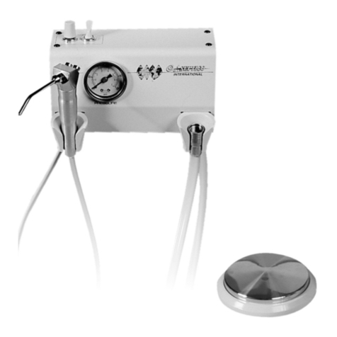
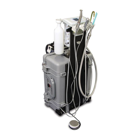
This service and parts manual offers information and
parts lists not available in the AEU-425CF/CF
Operation and Maintenance Instruction Manual. It will
help you better understand how the AEU-425CF/CF
Transport II MDS portable dental system works,
thereby reducing service time. Parts drawings, parts
photographs, and schematic diagrams show compo-
nents in their actual places in the unit relative to one
another. A plumbing schematic is provided with water
lines indicated in blue. Plumbing parts are called out by
Aseptico part number in the assembly drawings. An
electrical schematic is provided with wires color coded.
Electrical parts are called out by Aseptico part number
in the assembly drawings. Parts, with photo callouts, are
listed in the Parts List. Parts marked “commercially
available” are those items that can be purchased at
retail hardware stores, and minimize service delays
when obtained locally. Use the information in the Parts
List when ordering replacement parts.
Insp ction & Op ration V rification
To verify that the AEU-425CF/CF unit is functioning
properly, first follow the set-up procedure in the
Operation & Maintenance manual. Note that connectors
from the waste tank must be connected to the underside
of the plumbing chassis in order for the compressor
motor to turn on. The high vacuum hose is placed in the
toggle holder with the yellow dot and the saliva ejector
vacuum hose is placed in the toggle holder with the red
dot (see Fig. 1). The reason for this is that the unit is
operated by a single dual headed compressor.
The compressor is set up to work one head as a
pressure side and the other head as the high vacuum
side. This is accomplished by using a three way solenoid
on the pressure side in conjunction with a pressure
switch and relay. The three way solenoid allows for air
from the pressure side to be distributed to the air
canister or to the atmosphere. When the power switch
is turned on, the pressure switch will activate the relay
and start the compressor motor. The compressor motor
will turn on and the pressure gauge will start to climb to
50 PSI in a few seconds. The delay prevents stalling of
the compressor and is shorter once the unit is pressur-
ized. When ever the compressor motor is on, the high
vacuum tube will be on. Stalling of the compressor on
the vacuum side is prevented by using a vacuum pump
plumbed to the input and the output of the head to
Figure 1
Yellow
Dot
Red Dot
Figure 2
Adjustment Screws
Water
Filter
Figure 3
