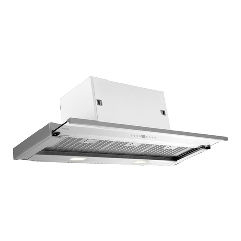
Asko CW4611 User manual

Operation instructions Wall-mounted Cooker Hood EN
Gebruiksaanwijzing Wandgemonteerde afzuigkap NL
Инструкция по эксплуатации Настенная вытяжка RU

Operating Instructions
Wall-mounted Cooker Hood
ASKO CW4611
ASKO CW4631
ASKO CW4651
ASKO CW4671
ASKO CW4911
ASKO CW4951
ASKO CW4971
ASKO CW4931
Dear Customer,
Thank you for choosing this quality product from ASKO.
We hope it will meet your expectations and fulfil your needs
for many years to come. Scandinavian design combines clean
lines, everyday functionality and high quality. These are key
characteristics of all our products and the reason they are
greatly appreciated throughout the world.

3
CONTENTS
SAFETY INFORMATION 4
General 4
Recycling 4
Electrical safety 4
DESCRIPTION OF THE CONTROLS 5
DESCRIPTION OF THE DISPLAY 5
USING THE EXTRACTOR FAN 6
Starting and stopping the fan 6
Activating Turbo mode 6
Setting the clock 6
Auto off 6
Activating the egg timer 6
Light 6
Energy saving mode for the display 6
CARE AND CLEANING 7
General 7
Cleaning the grease filter 7
Replacing the charcoal filter (standard hood) 7
Replacing the charcoal filter (for hood with sloping surface) 7
Emptying and cleaning the fat collector 8
Replacing the bulbs 8
TROUBLESHOOTING 9
ELECTRICAL CONNECTION 10
INSTALLATION ALTERNATIVES 10
INSTALLATION 11
Unpacking 11
Fixing to the wall 11
Mounting the extensible cover plate 12
High ceiling? 12

4
General
These operating instructions contain important
information on installation and maintenance that
ought to be read very carefully. Keep these oper-
ating instructions for future reference.
• Never inspect the grease or charcoal filters
when the extractor fan is in use.
• Do not touch the halogen lamps or nearby
surfaces when the lamps have been on for
some time. Risk of burn injury!
• Do not flambé food under the cooker hood.
• When frying, the pan must not be left un-
watched. Overheated oil can pose a fire risk.
• Always unplug the appliance before per-
forming maintenance.
• The cooker hood must not be used by chil-
dren.
• If the cooker hood is used with a gas hob,
there must be sufficient ventilation in the
room to prevent a pressure drop, which can
otherwise extinguish the gas flame.
• This appliance is not intended for use by
children, the elderly or infirm or persons with
reduced physical sensory or mental capabili-
ties unless supervised by a person responsi-
ble for their safety.
• Young children should be supervised to en-
sure that they do not play with the appliance
SAFETY INFORMATION
Recycling
This appliance complies with European Commu-
nity directive 2002/96/EC, Waste Electrical and
Electronic Equipment (WEEE). By ensuring that
this product is recycled responsibly, the user helps
prevent possible negative impact on the environ-
ment.
NB:
Dispose of this product responsibly. Irresponsible
disposal can result in negative environmental
impact or personal injury.
Under no circumstances may this
extractor fan be disposed of as
household waste. It must be taken
to a recycling centre for electrical
and electronic equipment.
This product must be disposed of in accordance
with local legislation.
For more information on disposal, recycling and
reuse of this product, contact your local authority,
your household waste collection service or the
store where you purchased the product.
Electrical safety
Check the type plate (found inside the cooker
hood) to ensure that the rated voltage and cur-
rent matches the power supply and that the plug
matches the socket. Consult a qualified electrician
if in any doubt.
Installation
See the INSTALLATION chapter for information.
xs
5
DESCRIPTION OF THE CONTROLS
1 Filter cleaning indicator/clock activation button
2 Timer activation button
3 Reduce speed/hour setting button
4 Display
5 Increase speed/minute setting button
6 Egg timer setting button
7 Light button
1 Light indicator
2 Auto off indicator
3 Auto off time display
4 Alarm time display
5 Alarm indicator
6 Clock/time display
7Grease filter cleaning indicator (De-
activate by pressing on the
control panel).
8 Turbo mode indicator
9 Fan speed indicator
1 2 3 4 5 6 7
DESCRIPTION OF THE DISPLAY
1 2 3
456789

6
USING THE EXTRACTOR FAN
Starting and stopping the fan
Press or to start the fan. Use the same but-
tons to stop the fan.
Example:
If using the lowest power setting, press once
to stop the fan.
If using the highest power setting, use to stop
the fan.
Activating Turbo mode
Press one or more times. When Turbo mode is
activated is displayed. After two minutes
in Turbo mode, the fan automatically switches to
speed three.
Setting the clock
Set the clock as follows:
1. Press and hold for 3 seconds. The figures
in the display will start to flash.
2. Use to switch between hours and min-
utes.
3. Use to decrease and to increase the
time.
Auto off
Switch on the fan's auto off function as follows:
1. Start the fan.
2. Press . The lamp lights and
flashes.
3. Use to switch between hours and min-
utes.
4. Use to decrease and to increase the
time.
Press and hold for 3 seconds to deactivate
auto off.
Activating the egg timer
Use the alarm for cooking reminders. Set the
alarm time as follows:
1. Press . The lamp and flash.
2. Use to switch between hours and min-
utes.
3. Use to decrease and to increase the
time.
4. Press to turn off the alarm.
Press and hold for 3 seconds to deactivate the
alarm before it sounds.
Light
Press to switch the lamp on or off.
Energy saving mode for the
display
The display automatically enters energy saving
mode if no buttons are pressed within a certain
time. To reactivate the display, simply press
any button once.
REMEMBER!
The extractor fan should be started before
cooking begins. To completely eliminate all
steam and odours, the extractor fan should
be left running for 15 minutes after cooking
is finished.

7
CARE AND CLEANING
General
Regular maintenance is required to ensure that
the cooker hood functions properly. This is espe-
cially true of the grease and charcoal filters.
Clean the fan and other surfaces of the cooker
hood regularly with a cloth dipped in denatured
alcohol or a non-abrasive liquid cleaner.
The charcoal filter cleans the circulating air in the
room. Such filters cannot be cleaned or recycled
and must be replaced at least every four months.
The speed at which the charcoal filter becomes
saturated depends on how often the fan is used,
the type of food that is cooked and how often the
grease filter is cleaned.
To prevent the risk of fire and to ensure that the
cooker hood functions properly, the grease filter
must always be cleaned as instructed below when
the display indicates the need or at least every
two months.
Cleaning the grease filter
Remove the filter from the cooker hood and clean
it in a solution of water and neutral cleaning
liquid. Leave the filter to soak in the solution for a
while.
- Rinse thoroughly with hot water and leave the
filter to dry.
- The filter can also be cleaned in a dishwasher.
The colour of the grease filter may change after a
few washes. This is normal.
NB:
If you clean the grease filter in the dishwasher:
load only the grease filter and no other items as
food particles from dishes can fasten in the filter.
Replacing the charcoal filter (standard
hood)
Replace the charcoal filter (standard hood) as
follows:
1. Remove the grease filter.
2. Squeeze the clips on the charcoal filter and
pull the charcoal filter back to remove it.
Replacing the charcoal filter (for
hood with sloping surface)
1. Press the middle of the right edge of the
glass cover to open it.
2. Remove the grease filter.
3. Squeeze the clips on the charcoal filter and
pull the charcoal filter back to remove it.
REMEMBER!
The charcoal filter must be replaced at least
every four months during normal fan use.
The grease filter must be cleaned when the
display indicates the need or at least every
two months.

8
Emptying and cleaning the fat collector
The fan is fitted with a fat collector that collects fat
from the fan blades and fan housing.
1. Remove the grease filter and the charcoal
filter (if fitted).
2. Remove the fat collector and clean it in warm
water with washing up liquid. It can also be
cleaned in a dishwasher.
Replacing the bulbs
Replace the bulbs as follows:
1. Lift up and remove the light fitting with a
screwdriver or other suitable tool.
2. Remove the blown halogen bulb (if the fan
has 4 bulbs = 10W, 2 bulbs = 20W). Remem-
ber that the bulb can be hot!
3. Insert the new halogen bulb.
If you touch the halogen bulb with your bare
hands this may reduce its service life. Always use a
glove or a cloth to avoid direct contact.
NB:
The light is only meant for use during cooking and
not for illuminating the surroundings for longer
periods. If the light is used for longer periods, this
will considerably shorten the burn time of the
bulbs.
CARE AND CLEANING

9
TROUBLESHOOTING
Problem Possible cause Solution
Cooker hood does not work No power supply Check that the plug is
connected
Poor air flow Aluminium grease filter blocked Clean grease filter and
replace once dry
Charcoal filter blocked Replace charcoal filter
Motor running, but no air flow Butterfly valve jamming Call the service divi-
sion
Motor stops after a few minutes Overheating cut-out activated The kitchen is insuffi-
ciently ventilated
The cooker hood has been installed
too close to the hob
The hood must be at
least 65 cm from the
hob
Strong smell of cooking No charcoal filter fitted For circulation use (in-
stallation alternative A),
the charcoal filter must
be fitted
Oil drops onto the hob Fat collector missing or not fitted Remove the aluminium
grease filter and fit the
fat collector
Aluminium grease filter saturated Clean filter
Humming sound Something touching the fan blades Call the service divi-
sion
GUARANTEE AND SERVICE
Before booking a service call, read the TROUBLESHOOTING
chapter above. For more information on service and guarantee
conditions, see the enclosed separate information.

10
ELECTRICAL CONNECTION
Installation and electrical connections must be performed by qualified professionals.
The cooker hood is manufactured in compliance with Class I and as such must be
earthed.
Connect the cooker hood to the electrical supply as instructed below.
IEC227 North America
L=phase Brown Black
N=neutral Blue White
E=earth Green/yellow Green
If the cable lacks a plug, fit a plug suitable for the electrical load specified on the rating
plate. If the cable is fitted with a plug, the cooker hood shall be installed so that the plug
is easily reached.
If the cooker hood is connected directly to the electrical supply, a multipolar circuit
breaker with at least a 3 mm contact clearance must be fitted between the cooker hood
and the electrical supply in accordance with the electrical load and applicable regula-
tions.
The cooker hood can be installed in the following ways:
• Circulating indoor air (A)
• Outdoor venting (B)
INSTALLATION ALTERNATIVES

11
INSTALLATION
Unpacking
Remove the packaging with the product in
place. Cut off the packing ribbons and carefully
cut open the packaging (do not cut too deeply),
remove the packaging.
Check that the product is free from transport
damage. Any damage shall be reported imme-
diately to the carrier or seller.
Damage, faults and missing parts must be
reported immediately to the seller.
Fixing to the wall
Remove grease filter(s) before installing the
cooker hood.
Prepare the hole for the exhaust air if the cooker
hood is to be installed with outdoor venting.
Drill two holes in the wall spaced as illustrated
(A).
Insert and tighten the screws so that you can
still adjust the cooker hood. Once this is done,
tighten it firmly against the wall.
10mm
260mm
NB:
Always use screws and fittings suited to the
type of wall (concrete, plasterboard etc.). If
screws and fittings are included with the prod-
uct, make sure they are suitable for the type of
wall on which the cooker hood is to be mounted
before using them.
REMEMBER!
• The distance between the top of the hob and
the lowest part of the cooker hood must be
at least 65 cm.
• If a two-part connection tube is used, the
lower section must sit outside the upper sec-
tion.
• Do not connect the cooker hood exhaust to
a duct used to circulate hot air or vent steam
from another appliance.
• Always use protective gloves when installing
the appliance!

12
Mounting the extensible cover plate
Run the power supply so that it fits inside the
cover plate.
Adjust the mounting plate by pulling it apart or
pushing it together so that it fits the cover plate.
Then screw the mounting plate to the wall (A).
Screw the cover plate to the mounting plate (B).
If installing as in alternative B (outdoor venting),
you must now fit an approved ventilation tube
that can be purchased from the same store as the
cooker hood. Fit following the instructions includ-
ed with the tube. Connect the ventilation tube to
the connecting flange of the cooker hood (C).
NB:
If the cooker hood is installed as in alternative A
(circulating indoor air), the charcoal filter availa-
ble for purchase from your dealer must be fitted.
INSTALLATION
High ceiling?
If the ceiling is higher than 2.60-2.70 metres, for
certain models you can order a chimney extender
for ceiling heights up to 3.5 metres.

Gebruiksaanwijzing
Wand afzuigkap
ASKO CW4611
ASKO CW4631
ASKO CW4651
ASKO CW4671
ASKO CW4911
ASKO CW4951
ASKO CW4971
ASKO CW4931
Geachte klant,
Bedankt dat u voor dit kwaliteitsproduct van ASKO hebt
gekozen. Wij hopen dat het product jarenlang aan uw wen-
sen en verwachtingen zal voldoen. Scandinavisch design is
een combinatie van heldere lijnen, alledaagse functionaliteit
en hoogstaande kwaliteit. Dit zijn de hoofdkenmerken van
al onze producten en de reden dat onze producten wereld-
wijd zo geliefd zijn.

14
INHOUD
VEILIGHEIDSINFORMATIE 15
Algemeen 15
Recycling 15
Elektrische veiligheid 15
BESCHRIJVING VAN HET BEDIENINGSPANEEL 16
BESCHRIJVING VAN HET DISPLAY 16
DE AFZUIGKAP GEBRUIKEN 17
De motor starten en stoppen 17
Turbo-modus activeren 17
De klok instellen 17
Automatische uitschakeling 17
De timer activeren 17
Verlichting 17
Energiebesparende modus voor de display 17
ONDERHOUD EN REINIGING 18
Algemeen 18
Het vetfilter reinigen 18
Het koolfilter vervangen (standaardkap) 18
Het koolfilter vervangen (voor kap met schuin oppervlak) 18
De vetopvangbak legen en reinigen 19
De lampen vervangen 19
PROBLEMEN VERHELPEN 20
ELEKTRISCHE AANSLUITING 21
INSTALLATIEMOGELIJKHEDEN 21
INSTALLATIE 22
Uitpakken 22
Bevestiging aan de wand 22
De verlengbare afdekplaat monteren 23
Hoog plafond? 23

15
Algemeen
Deze gebruiksaanwijzing bevat belangrijke infor-
matie over de installatie en het onderhoud die
zorgvuldig doorgelezen moet worden. Bewaar
deze gebruiksaanwijzing voor toekomstig ge-
bruik.
• Inspecteer de vet- of koolfilters nooit wan-
neer de afzuigkap aan staat.
• Raak de halogeenlampen of nabijgelegen
oppervlakken niet aan wanneer de lampen al
enige tijd branden. Kans op brandwonden!
• Flambeer geen eten onder de afzuigkap.
• Houd tijdens frituren de pan altijd in de
gaten. Oververhitte olie kan brand veroorza-
ken.
• Ontkoppel het apparaat altijd van de stroom
voordat u onderhoud verricht.
• De afzuigkap mag niet door kinderen
worden gebruikt.
• Indien u de afzuigkap in combinatie met
een gasfornuis gebruikt, moet de kamer
voldoende geventileerd worden om een
drukval te voorkomen, die de gasvlam zou
kunnen doven.
VEILIGHEIDSINFORMATIE
Recycling
Dit apparaat voldoet aan richtlijn 2002/96/EG
van het Europese parlement, Afgedankte Ele-
ktrische en Elektronische apparatuur (AEEA).
Door dit product op de juiste manier te recyclen,
helpt u negatieve gevolgen voor het milieu te
voorkomen.
N.B.!
Dank dit product op verantwoorde wijze af. On-
verantwoord afdanken kan resulteren in nega-
tieve gevolgen voor het milieu of in persoonlijk
letsel.
Deze afzuigkap mag onder geen en-
kele voorwaarde worden afgedankt
als huishoudelijk afval. De afzuigkap
moet naar een recyclecentrum voor
elektrische en elektronische appa-
ratuur worden gebracht.
Dit product moet worden afgedankt in overeen-
stemming met de lokale wetgeving.
Neem voor meer informatie over het afdanken,
recyclen en hergebruiken van dit product contact
op met de lokale autoriteiten, het afvalbedrijf
voor huishoudelijk afval of de winkel waar u dit
product hebt gekocht.
Elektrische veiligheid
Controleer op het typeplaatje (aan de binnenkant
van de afzuigkap) of de nominale spanning en
stroom overeenkomt met de stroomtoevoer en of
de stekker in het stopcontact past. Raadpleeg bij
twijfel een erkende elektriciën.
Installatie
Zie het hoofdstuk INSTALLATIE voor meer infor-
matie.

16
BESCHRIJVING VAN HET BEDIENINGSPANEEL
1 Activeerknop indicator filterreiniging/klok
2 Activeerknop timer
3 Instelknop snelheid/uur
4 Display
5 Instelknop snelheid/minuut verhogen
6 Instelknop timer
7 Knop verlichting
1 Indicator lamp
2 Indicator automatische uitschakeling
3 Tijddisplay automatische
uitschakeling
4 Tijddisplay alarm
5 Indicator alarm
6 Display klok/tijd
7 Indicator reiniging vetfilter (Uitschake-
len door te drukken op het
bedieningspaneel)
8 Indicator turbo-modus
9 Indicator afzuigsnelheid
1 2 3 4 5 6 7
BESCHRIJVING VAN HET DISPLAY
1 2 3
456789

17
DE AFZUIGKAP GEBRUIKEN
De motor starten en stoppen
Druk op of om de motor te starten. Ge-
bruik dezelfde knoppen om de motor te stoppen.
Voorbeeld:
Indien u de laagste vermogeninstelling gebruikt,
drukt u eenmaal op om de motor te stoppen.
Indien u de hoogste vermogeninstelling gebruikt,
drukt u op om de motor te stoppen.
Turbo-modus activeren
Druk één of meerdere keren op . Wanneer
de Turbo-modus is geactiveerd, wordt
weergegeven. Na twee minuten in de Turbo-
modus schakelt de motor automatisch naar stand
3.
De klok instellen
Stel de klok als volgt in:
1. Houd 3 seconden ingedrukt. De sym-
bolen op het display beginnen te knipperen.
2. Gebruik om tussen uren en minuten te
schakelen.
3. Gebruik om de tijd te verlagen en om
deze te verhogen.
Automatische uitschakeling
U kunt de functie voor automatische
uitschakeling als volgt activeren:
1. Start de motor.
2. Druk op . De lamp gaat branden en
knippert.
3. Gebruik om tussen uren en minuten te
schakelen.
4. Gebruik om de tijd te verlagen en om
deze te verhogen.
Houd 3 seconden ingedrukt om de automa-
tische uitschakeling te activeren.
De timer activeren
U kunt het alarm gebruiken als geheugensteun
tijdens het koken. Stel de alarmtijd als volgt in:
1. Druk op . De lamp gaat branden en
knippert.
2. Gebruik om tussen uren en minuten te
schakelen.
3. Gebruik om de tijd te verlagen en om
deze te verhogen.
4. Druk op om het alarm uit te schakelen.
Houd 3 seconden ingedrukt om het alarm te
deactiveren voordat het afgaat.
Verlichting
Druk op om de verlichting in of uit te schake-
len.
Energiebesparende modus voor het
display
Het display schakelt automatisch in de ener-
giebesparende modus als er gedurende een
bepaalde tijd geen knop wordt ingedrukt. U hoeft
alleen maar een willekeurige knop in te drukken
om het display opnieuw te activeren.
LET OP!
De afzuigkap moet worden gestart voordat u
begint met koken.
Indien u helemaal geen stoom en geuren
wilt zien of ruiken, moet u de afzuigkap 15
minuten laten draaien nadat u klaar bent met
koken.

18
ONDERHOUD EN REINIGING
Algemeen
Regelmatig onderhoud is vereist om ervoor te
zorgen dat de afzuigkap goed blijft functioneren.
Dit is voornamelijk van belang voor de vet- en
koolfilters.
Reinig de motor en andere oppervlakken van de
afzuigkap regelmatig met een doek die onderge-
dompeld is in gedenatureerde alcohol of een niet-
schurend vloeibaar schoonmaakmiddel.
Het koolfilter reinigt de circulatielucht in de
ruimte. Dergelijke filters kunnen niet worden
gereinigd of gerecycled en moeten ten minste
elke vier maanden worden vervangen. Hoe snel
het koolfilter verzadigd wordt, hangt af van hoe
vaak de afzuigkap wordt gebruikt, het type eten
dat wordt bereid en hoe vaak het vetfilter wordt
gereinigd.
Het vetfilter moet altijd worden gereinigd vol-
gens de bovenstaande aanwijzingen wanneer dit
op het display wordt aangegeven of ten minste
elke twee maanden om brand te voorkomen en
om ervoor te zorgen dat de afzuigkap goed blijft
functioneren.
Het vetfilter reinigen
Verwijder het filter uit de afzuigkap en reinig het
filter in een oplossing van water en een neutraal
schoonmaakmiddel. Laat het filter enige tijd
weken in de oplossing.
- Spoel het filter grondig af met heet water en laat
het filter drogen.
- U kunt het filter ook in een vaatwasser reinigen.
De kleur van het vetfilter kan na enkele wasbeur-
ten veranderen. Dit is gebruikelijk.
NB:
Als u het vetfilter in de vaatwasser schoonmaakt:
doe er alleen het vetfilter in en geen andere voor-
werpen, aangezien etensresten in het filter vast
kunnen gaan zitten.
Het koolfilter vervangen
(standaardkap)
Vervang het koolfilter (standaardkap) als volgt:
1. Verwijder het vetfilter.
2. Knijp in de klemmen van het koolfilter en
trek het koolfilter naar achteren om deze te
verwijderen.
Het koolfilter vervangen (voor kap met
schuin oppervlak)
1. Druk op het midden van de rechterrand van
de glazen afdekking om deze te openen.
2. Verwijder het vetfilter.
LET OP!
Het koolfilter moet ten minste elke vier maan-
den vervangen worden bij normaal gebruik
van de afzuigkap.
Het vetfilter moet worden vervangen wanneer
dit op het display wordt aangegeven of ten
minste elke twee maanden.

19
3. Knijp in de klemmen van het koolfilter en
trek het koolfilter naar achteren om deze te
verwijderen.
De vetopvangbak legen en reinigen
De afzuigkap is uitgerust met een vetopvangbak
waarin het vet van de motorbladen en –behuizing
wordt opgevangen.
1. Verwijder het vetfilter en het koolfilter (in-
dien aanwezig).
2. Verwijder de vetopvangbak en reinig deze
in warm water met vloeibaar afwasmiddel. U
kunt de bak ook in een vaatwasser reinigen.
De lampen vervangen
U kunt als volgt de lampen vervangen:
1. Til de lampfitting omhoog en verwijder deze
met een schroevendraaier of een soortgelijk
voorwerp.
2. Verwijder de kapotte halogeenlamp (als de
ventilator 4 lampen heeft = 10 W, 2 lampen =
20 W). Let op: de lamp kan heet zijn!
ONDERHOUD EN REINIGING
3. Plaats de nieuwe halogeenlamp.
Als u de halogeenlamp aanraakt met uw blote
handen, kan dat de levensduur van de lamp ver-
minderen. Gebruik altijd een handschoen of een
doek om direct contact te vermijden.
N.B.!
De lamp is alleen bedoeld voor gebruik tijdens
het koken en niet om de omringende omgeving
langere periodes te verlichten. Indien de lamp
langere periodes wordt gebruikt, zal dat de leven-
sduur van de lampen aanzienlijk verkorten.

20
PROBLEMEN VERHELPEN
Probleem Mogelijke oorzaak Oplossing
Afzuigkap functioneert niet Geen stroomtoevoer Controleer of de stekker
in het stopcontact zit
Slechte luchtstroom Aluminium vetfilter geblokkeerd Reinig het vetfilter en
plaats het filter terug na
het drogen
Koolfilter geblokkeerd Vervang het koolfilter
Motor draait, maar er is geen
luchtstroom
Terugslagklep verstopt Neem contact op met
de serviceafdeling
Motor stopt na een paar minuten Oververhittingsbeveiliging geac-
tiveerd
De keuken wordt on-
voldoende geventileerd
De afzuigkap is te kort boven het
kooktoestel geïnstalleerd
De kap moet ten minste
65 cm boven het kook-
toestel hangen
Sterke kookgeuren Geen koolfilter geplaatst Bij recirculatie(installati
emogelijkheid A) moet
een koolfilter worden
geplaatst
Er druppelt olie op het kooktoestel Vetopvangbak ontbreekt of is niet
bevestigd
Verwijder het alumini-
um vetfilter en plaats de
vetopvangbak
Aluminium vetfilter verzadigd Reinig filter
Zoemgeluid Iets raakt de motorbladen Neem contact op met
de serviceafdeling
GARANTIE EN SERVICE
Lees voordat u contact opneemt met de serviceafdeling het bo-
venstaande hoofdstuk PROBLEMEN VERHELPEN door.
Zie voor meer informatie over service- en garantievoorwaarden
de bijgesloten aparte informatie.
This manual suits for next models
7
Table of contents
Languages:
Other Asko Ventilation Hood manuals

Asko
Asko CCT1252W User manual

Asko
Asko CW4634S/4000 User manual

Asko
Asko CBB761SC User manual

Asko
Asko CH060-60 User manual

Asko
Asko CCT9051SC User manual

Asko
Asko CC4527S User manual

Asko
Asko CD4634B/4000 User manual

Asko
Asko CBB861S User manual

Asko
Asko A4402TRVS/E01 User manual

Asko
Asko ES1011QAM User manual
Popular Ventilation Hood manuals by other brands

Hansa
Hansa OKP6547SH operating instructions

GE
GE JN327, JV327, JV337, JV347 Owner's manual and installation instructions

Candy
Candy CFT610/5X/P instruction manual

Faber
Faber HEAVEN GLASS 2.0 instruction manual

Blaupunkt
Blaupunkt AP-5DA45450AU instruction manual

Schweigen
Schweigen EV-6UCQ installation guide