Aspire EVOKE 2 User manual

Aspire
Evoke 2
Aspire
Evoke 2 JNR
EVOKE 2 & EVOKE 2 JNR
USER MANUAL

Congratulations and thank you for choosing an Aspire Wheelchair.
This product has been designed to offer the maximum in comfort,
safety and adjustability. Aspire Evoke Wheelchairs are suitable for
indoor and outdoor use and are available in a range of sizes.
It is important that you read this user manual carefully
before using your new wheelchair.
TABLE OF CONTENTS
1. Symbols Used In This Manual 4
2. Symbols Used on the Product 4
3. Intended Use 5
4. Product Description 6
5. Warnings 6
6. Product Specifications 7
7. List Of Components 8
8. Assembly 9
9. Preliminary Checks 10
10. General Operation 10
11. Adjustments 15
12. Accessories 17
13. Amputee Setting Adjustment 25
14. Troubleshooting 27
15. Care & Maintenance 28
16. Warranty 29
17. Compliance 29
18. Service Maintenance & Customisation 29
19. Manufacturer, UK Representative & Importer Details 30
© Aidacare Pty Ltd 2023
No part of this user manual may be copied, distributed, reproduced, scanned or stored on any electronic database, whether in whole or in part in
any form or by any means.
Due care has been taken to ensure all the information contained in this user manual is correct at the time of printing. All measurements, pictures,
colours and weight capacities are to be used as a guide only. We reserve the right to modify the design or appearance of any product displayed in
this user manual without prior notice.
This product Features the UKCA mark, in compliance with Part II
UK MDR 2002 ( as amended ) Class 1.

54
1. SYMBOLS USED IN THIS MANUAL
The symbols below are used throughout this user manual and on the product to identify warnings and
important information. It is very important for you to read them and understand them completely.
WARNING
WARNING! Indicates a potentially hazardous condition/situation. Failure to follow
designated procedures can cause either personal injury, component damage or
malfunction. On the product, this icon is represented as a black symbol on a white triangle
with a black border.
ALWAYS! These actions should be performed as specified. Failure to perform mandatory
actions can cause personal injury and/or equipment damage. On the product, this icon is
represented as a white infinity symbol on a black dot with a white border.
DO NOT! These actions are prohibited. These actions should not be performed at any time
or in any circumstances. Performing a prohibited action can cause personal injury and/or
equipment damage. On the product, this icon is represented as a white symbol with a black
circle and black slash.
2. SYMBOLS USED ON THE PRODUCT
ASPIRE EVOKE 2 MANUAL WHEELCHAIR
This product is specifically designed for individuals who, due to a wide variety of reasons, have
limited mobility or are unable to walk. This product should be used as a tool to assist with mobility
or walking difficulties.
Attendant Propelled Wheelchairs are able to be propelled by an attendant with the push handles.
This wheelchair is designed for indoor and limited outdoor use. When used outdoors this wheelchair
must remain on sealed, level terrain (examples include but are not limited to shopping centres, medical
centres, flat and level footpaths, and environments with accessibility-focused layouts). When using
outdoors it is suggested that anti-tip wheels are fitted.
Self Propelled Wheelchairs are able to be propelled by a user with the self-propelling wheels or by
an attendant with the push handles. This wheelchair is designed for indoor and limited outdoor use.
When used outdoors this wheelchair must remain on sealed, level terrain (examples include but are
not limited to shopping centres, medical centres, flat and level footpaths, and environments with
accessibility-focused layouts. When using outdoors it is suggested that anti-tip wheels are fitted.
WARNING
WARNING! This wheelchair is intended to bear the weight of an occupant through its
wheels during propulsion and when stationary. It is NOT designed to be lifted/carried
with an occupant in the seat and doing so may cause serious injury or death.
ASPIRE EVOKE 2 JNR MANUAL WHEELCHAIR
This product is specifically designed for children who, due to a wide variety of reasons, have limited
mobility or are unable to walk. This product should be used as a tool to assist with mobility or
walking difficulties.
Attendant Propelled Wheelchairs are able to be propelled by an attendant with the push handles.
This wheelchair is designed for indoor and limited outdoor use. When used outdoors this wheelchair
must remain on sealed, level terrain (examples include but are not limited to shopping centres, medical
centres, flat and level footpaths, and environments with accessibility-focused layouts). When using
outdoors it is suggested that anti-tip wheels are fitted.
Self Propelled Wheelchairs are able to be propelled by a user with the self-propelling wheels or by
an attendant with the push handles. This wheelchair is designed for indoor and limited outdoor use.
When used outdoors this wheelchair must remain on sealed, level terrain (examples include but are
not limited to shopping centres, medical centres, flat and level footpaths, and environments with
accessibility-focused layouts. When using outdoors it is suggested that anti-tip wheels are fitted.
WARNING
WARNING! This wheelchair is intended to bear the weight of an occupant through its
wheels during propulsion and when stationary. It is NOT designed to be lifted/carried
with an occupant in the seat and doing so may cause serious injury or death.
3. INTENDED USE
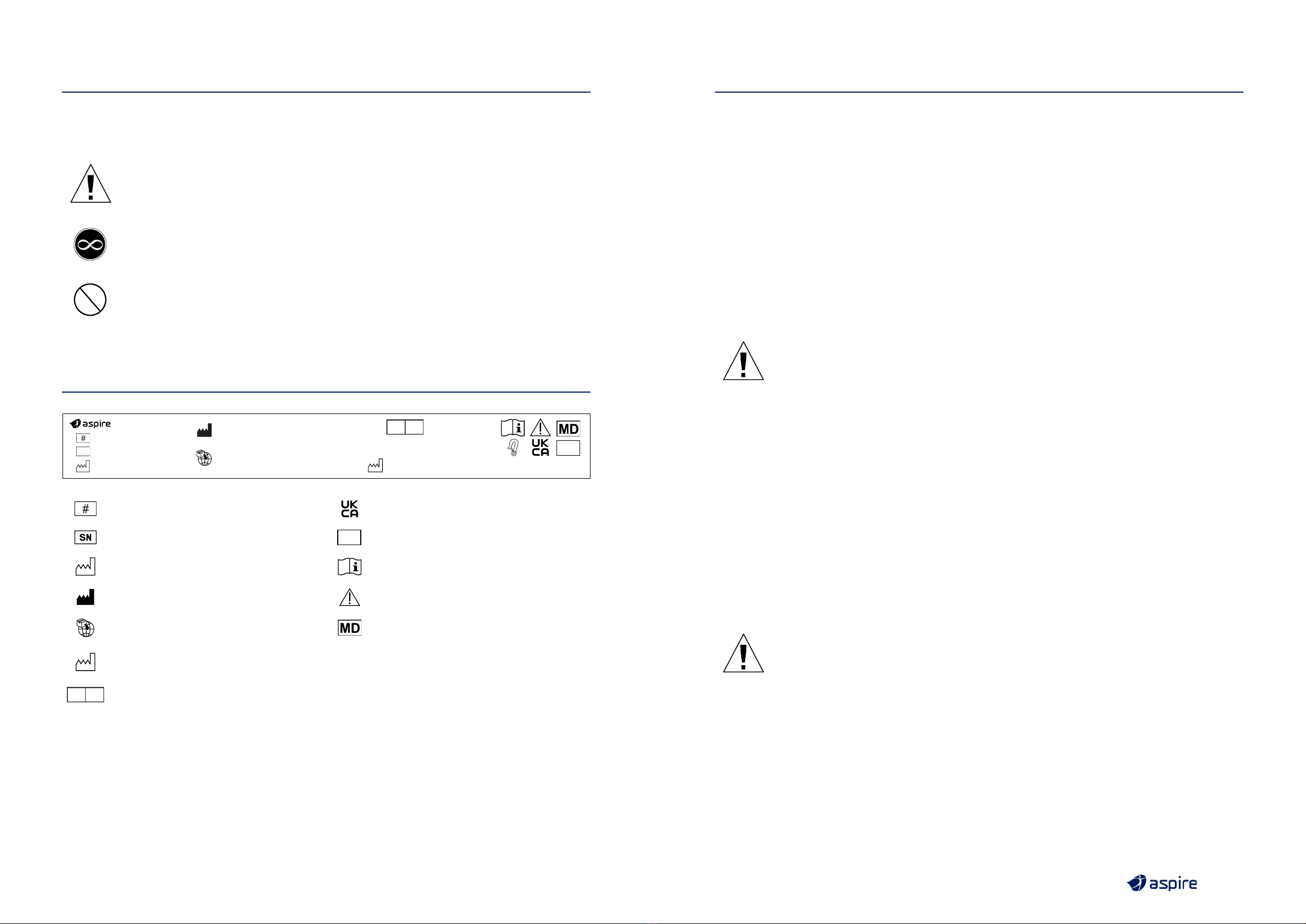
Product Code UKCA Mark
Serial Number SWL
140KG Safe Working Load
Manufacturing Date Read User Manual
Manufacturer Caution
Importer Medical Device
CN Country of Manufacture Crash Tested to ISO7176-19:2008
UK REP Authorised Representative in UK
EVOKE 2 WHEELCHAIR
MWS449500 | MWS449500-UK
SN
5 Ashley Road, Clevedon BS21 7UX
UK REP SGB QA/RA
Consulting Ltd
AUSTRALIA | Aidacare Pty Ltd | ABN 40 134 833
Building 3A, 1 Moorebank Avenue, Moorebank NSW 2170
1300 133 120 | product@aidacare.com.au
Manufactured:
UNITED KINGDOM | Aidacare Ltd | Registration 13785408
Arcadia House, Maritime Walk, Ocean Village,
Southampton SO14 3TL
01622 541235 | info@aidacare.co.uk
MADE IN PRC It is recommended that you
have this product serviced every 12 months
CN
SWL
140KG
ISO 7176-19:2008

76
4. PRODUCT DESCRIPTION
ASPIRE EVOKE 2 MANUAL WHEELCHAIR
The Aspire Evoke 2 Manual Wheelchair is a lightweight four wheel wheelchair with a cross folding frame.
The product is made of aircraft grade aluminium, ensuring strength, durability and easy movement. This
wheelchair offers enhanced manoeuvrability and stability, a wide size range and leading adjustability for
a customised fit. It is equipped with a fabric seat and back, seat cushion, push handles, large 24 inch rear
self-propelling quick release wheels and removable swing away legrests. A large range of accessories
can be fitted to the Aspire Evoke 2 Manual Wheelchair to improve its overall performance.
ASPIRE EVOKE 2 JNR MANUAL WHEELCHAIR
The Aspire Evoke 2 JNR Manual Wheelchair is a lightweight four wheel wheelchair with a cross folding
frame. The product is made of aluminium, ensuring strength durability and easy movement. This
wheelchair offers enhanced manoeuvrability and stability, a wide size range and leading adjustability
for a customised fit. It is equipped with a fabric seat and back, seat cushion, push handles, medium
20 inch rear self-propelling quick release wheels and removable swing away legrests. A large
range of accessories can be fitted to the Aspire Evoke 2 JNR Manual Wheelchair to improve its
overall performance.
5. WARNINGS
MAXIMUM WEIGHT CAPACITY – 150kg / 23.6st – 350 – 500mm / 13.7" – 19.6" SEAT WIDTHS
MAXIMUM WEIGHT CAPACITY – 190kg / 29.9st – 570 – 610mm / 22.4" – 24" SEAT WIDTHS
DO NOT exceed maximum user weight. This weight limit includes any accessories, shopping
or other personal items that may be carried on the chair. The maximum weight capacity is
defined with respect to a typical body shape, where body mass is evenly distributed. Users
with dysmorphic body shapes or amputees should be assessed by an accredited healthcare
professional prior to choosing/using this wheelchair.
DO NOT stand on the foot plates as the wheelchair may tip forwards. The foot plates are not
designed to be a weight bearing surface.
DO NOT use the wheelchair on escalators, even if accompanied by an attendant.
ALWAYS use push rims to bring the wheelchair to a stop. DO NOT use the brakes to stop
a moving wheelchair.
WARNING
WARNING! Pay attention to your fingers when folding or opening the wheelchair and when
self-propelling the chair with hands in close proximity to wheel spokes.
ASPIRE EVOKE 2 MANUAL WHEELCHAIR
CODE
SEAT
WIDTH
(mm / inches)
OVERALL
WIDTH
(mm / inches)
SEAT
DEPTH
(mm / inches)
SEAT
HEIGHT
(mm / inches)
BACKREST
HEIGHT
(mm / inches)
ARMREST
HEIGHT
(mm / inches)
MINIMUM
CHAIR
WEIGHT
(kg / lb)
SWL
(kg / st)
EVOKE 2
MWS449500
350 560 300 – 450 450 – 500 430 – 490 210 – 230 14.8 kg 150 kg
14" 22" 11.8" – 17.7" 17.1" – 19.6" 16.9" – 19.2" 8.26" – 9" 32.6lbs 23.6st
MWS449510
400 610 300 – 450 450 – 500 430 – 490 210 – 230 14.9 kg 150kg
16" 24" 11.8" – 17.7" 17.1” – 19.6” 16.9” – 19.2” 8.26" – 9" 32.8lbs 23.6st
MWS449520
450 660 300 – 450 450 – 500 430 – 490 210 – 230 15.0 kg 150 kg
18" 25.9" 11.8" – 17.7” 17.1” – 19.6” 16.9” – 19.2” 8.26” – 9” 33lbs 23.6st
MWS449530
500 710 400 – 550 450 – 500 430 – 490 210 – 230 15.1 kg 150 kg
20" 27.9" 15.7" – 21.6" 17.1” – 19.6” 16.9” – 19.2” 8.26” – 9” 33.2lbs 23.6st
MWS449540
HD
570 780 400 – 550 450 – 500 430 – 490 210 – 230 16.0 kg 190 kg
22" 30.7" 15.7" – 21.6” 17.1” – 19.6” 16.9” – 19.2” 8.26” – 9” 35.2lbs 29.9st
MWS449550
HD
610 820 400 – 550 450 – 500 430 – 490 210 – 230 16.2 kg 190 kg
24" 32.2" 15.7" – 21.6” 17.1” – 19.6” 16.9” – 19.2” 8.26” – 9” 35.7lbs 29.9st
ASPIRE EVOKE 2 JNR MANUAL WHEELCHAIR
CODE
SEAT
WIDTH
(mm / inches)
OVERALL
WIDTH
(mm / inches)
SEAT
DEPTH
(mm / inches)
SEAT
HEIGHT
(mm / inches)
BACKREST
HEIGHT
(mm / inches)
ARMREST
HEIGHT
(mm / inches)
MINIMUM
CHAIR
WEIGHT
(kg / lb)
SWL
(kg / st)
EVOKE 2 JNR
MWS449560
300 mm 510 300 – 450 410 – 450 430 – 490 210 – 230 14 kg 150 kg
12” 20" 11.8" – 17.7" 16.1" – 17.7" 16.9" – 19.2" 8.2" – 9" 30.8lbs 23.6st
6. PRODUCT SPECIFICATIONS

98
7. LIST OF COMPONENTS
ASPIRE EVOKE 2 MANUAL WHEELCHAIR
1
2
3
4
7
8
9
10
5
6
No. Description
1Rear Wheels
2 Quick Release Axles
3Armrests
4Footrests
5 Height Adjustable Castor Fork
6Front Castor Wheel
7 Foot Plate with Heel Loop
8 Attendant Hand Grips
9Hand Brakes
10 Cross Bar
ASPIRE EVOKE 2 JNR MANUAL WHEELCHAIR
1
2
3
4
7
8
9
10
5
6
No. Description
1Rear Wheels
2 Quick Release Axles
3Armrests
4Footrests
5 Height Adjustable Castor Fork
6Front Castor Wheel
7 Foot Plate with Heel Loop
8 Attendant Hand Grips
9Hand Brakes
10 Cross Bar
Wheelchairs come with a left and
right legrest.
a. Insert the legrest into the
corresponding receiver at a 90º
angle (as shown).
b. Twist and hold the latch,
simultaneously rotating the legrest
towards the centre until it clicks into
place. Repeat for the other side.
8. ASSEMBLY
BOX CONTAINS:
Wheelchair frame fitted with rear wheels
• Wheelchair
• Left Legrest
• Right Legrest
• Allen Keys (4mm, 5mm)
• User Manual
• Seat Cushion
1
When opening the carton, ensure it
is done in a safe and careful manner.
DO NOT USE a box cutter or sharp
implement as this may damage the
product. For WH&S purposes, lay the
carton on its side with the top of the
carton open and slide the plastic bag
out containing the wheelchair.
2
3
Push
Rotate
towards centre
Place the wheelchair on levelled ground.
Then pushdown on the side rails of the seat
until flat.
Secure the cushion onto the base.
a
b
REMOVING LEGRESTS:
Twist and hold the
hook outwards
and lift.

1110
9. PRELIMINARY CHECKS
After assembling the wheelchair, these checks should be completed prior to initial use:
1. Check that the seating surface is locked into place, creating a flat support surface.
2. Check that rear wheels are locked in place and that quick release axle is not loose.
3. Check that rear brakes engage and disengage.
4. If fitted with accessories, ensure that they are secure and locked in place.
10. GENERAL OPERATION
10.1 GENERAL OPERATION
It is very important that this wheelchair is used under guidance from all warnings or hazards listed in this
product user manual. Key safety measures should be taken by both users and attendants when using
this wheelchair:
• Avoid quick direction changes.
• Ensure your wheelchair is used on surfaces intended for its use.
• Ensure an attendant is available to assist at all times.
10.2 LIFTING THE WHEELCHAIR
To fold your chair correctly follow the ‘ASSEMBLY’ instructions
in reverse 3, 2, 1.
Then, use the carry handle on the seating surface to safely lift
the wheelchair.
DO NOT lift the wheelchair with an occupant in
the seat. This lifting guide is for safe handling of
the wheelchair only.
WARNING
WARNING! DO NOT lift the wheelchair by holding it
by the legrests or the armrests! Fold-up the legrests
prior to lifting the chair.
10.3 TRANSPORTING THE WHEELCHAIR
WITHOUT OCCUPANT
To transport this chair in a motor vehicle it is suggested that
the backrest, seat and legrests are folded as per the “Lifting the
Wheelchair” instructions above. This will help reduce the overall
chair size in order to fit into the rear boot or backseat of a standard
motor vehicle.
10.4 MOVING WHEELCHAIR UP A KERB OR
SINGLE STEP WITH AN ATTENDANT
1. Push the wheelchair up to the kerb FEET FIRST.
2. The attendant should push down on the rear foot
peg to slightly incline the chair.
DO NOT tilt the chair back with the push handles.
3. Once the front wheels are firmly on the ground
above the kerb, the rear wheels should be pushed
against the kerb to propel the entire chair to rest
above the kerb.
Product may vary to image.
WARNING
WARNING! This should only ever be done
with an attendant and not performed by
a user on their own. It is very important
the above steps are followed to prevent
injury to both the user and the attendant.
Product may vary to image.
WARNING
WARNING! This should only ever be done
with an attendant and not performed by
a user on their own. It is very important
the above steps are followed to prevent
injury to both the user and the attendant.
10.5 MOVING WHEELCHAIR DOWN A KERB
OR SINGLE STEP WITH AN ATTENDANT
1. Reverse the wheelchair up to the kerb FEET LAST.
2. The attendant should check for cars or obstructions
prior to commencing the descent.
3. The attendant should slowly lower the rear wheels
down to the road surface, ensuring not to tip the chair.
4. Once the rear wheels are firmly on the road surface,
the front wheels should be slowly lowered onto the
road surface.
WARNING
Warning! Slopped or uneven terrain
This wheelchair is designed for use on flat-level surfaces. If encountering sloped or uneven
terrain an alternative route should be sought. If impossible a carer should always be present,
and use the attendant brakes to control speed and ensure the wheelchair to continues
straight forward until reaching flat ground.
WARNING
Warning! Maintaining stationary position
When not propelling the wheelchair the brakes should be applied in the locked position
at all times.
OTHER IMPORTANT WARNINGS

1312
WARNING
Warning! Avoid reaching from within the wheelchair
To ensure the upright stability of the wheelchair, never reach for objects as this changes
the centre of mass and may cause the chair to tip over in the direction of reaching. This
warning relates to reaching in any direction outside the perimeter of the wheelchair.
WARNING
Warning! Protecting hands when self-propelling
When slowing or braking the wheelchair using the self-propelling hand rims, heat can be
created via friction. To protect the skin integrity of the hands, it is strongly suggested that
the user wear wheelchair gloves.
WARNING
WARNING! DO NOT travels down kerbs or single steps without an attendant carer
NEVER attempt to transit down multiple steps with or without an attendant carer.
WARNING
WARNING! When self-propelling the wheelchair, it is strongly suggested that anti-tip wheels
are fitted. If anti-tip wheels are in the raised position or not fitted to the chair an attendant
carer should stand behind the wheelchair holding the handles.
SAFE USE
UNSAFE USE
10.6 TRANSPORTING THE WHEELCHAIR WITH AN OCCUPANT
Aspire Evoke 2 & Evoke 2 JNR wheelchairs are compliant to ISO7176-19:2008 & AS/NZS 3696.19t
(Wheelchairs wheeled mobility devices for use as seats in motor vehicles). These are approved to be
used in compliant vehicles when fitted with a headrest. (See page 23 – Deluxe Headrest).
To secure Aspire Evoke 2 & Evoke 2 JNR wheelchairs, the below steps must be followed:
1. Identify tie down points
(4 in total) on wheelchair
frame, these are identified
with a tie down logo.
2. Apply wheelchair brakes.
(Both sides)
3. Secure all four tie down
points ensuring the chair is
firmly secured to the vehicle
not allowing any movement
whilst being transported.
4. Fasten seat belt over the
occupants shoulder, passing
over their lap, down beside
the rear wheel and locking
into place in the buckle
located on the floor of
the vehicle.
2

1514
WARNING! DO NOT transport an occupant in the wheelchair if the above process is not correctly
followed. It is imperative that these steps are completed in order to ensure user safety. The wheelchair
is to always be facing the same direction of seats within the vehicle, not to the side or backwards.
10.7 USING THE WHEELCHAIR BRAKES
Aspire Evoke 2 Manual Wheelchairs have locking brakes to ensure no movement occurs when the
wheelchair is in a stationary position.
1. To engage brakes, push
forward on the brake lever
until firmly locked in place.
2. To disengage brakes, pull
back on the brake lever
until unlocked.
WARNING
WARNING! Brakes should always be locked when leaving a user unattended in the wheelchair.
10.8 QUICK RELEASE WHEELS
If the rear wheels need to be removed for repair or replacement,
quick release axles are fitted to assist.
1. To detach the rear wheel from the frame, press & hold the release
button and remove the wheel from the frame.
2. To attach wheel, reverse step 1.
WARNING
WARNING! Ensure quick release axles are mounted correctly and locked in place prior to
seating a user.
1
2
1
Aspire Evoke 2 & Evoke 2 JNR Manual Wheelchairs have multiple adjustment points to ensure maximum
comfort for users. It is very important that the below steps are followed when adjusting the wheelchair
to ensure maximum safety.
11. ADJUSTMENTS
12
11.1 BACKREST HEIGHT
ADJUSTMENT
1. Peel back upholstery in the
lower edge of the backrest
cane to reveal two bolt heads.
2. Remove 8 bolts (4 x each
side) and reposition canes
as required.
3. Tighten bolts and
reattach upholstery.
12
11.2 BACKREST TENSION
ADJUSTMENT
1. Peel back upholstery
to reveal Velcro
adjustment straps.
2. Reposition straps to desired
position and reapply
upholstery securing in place
with Velcro.
NOTE: Ensure the rear wheels are located in symmetrical positions on both sides of the chair
to maintain stability.
12
11.3 SEAT DEPTH AND
REAR WHEEL
ADJUSTMENT
1. Remove all bolts as shown
and move backrest receiver
bracket to the desired
seat depth.
2. To adjust rear wheel
position and height, the
axle mount and receiver
can be adjusted as shown.
Once at the desired position,
ensure all hardware is
tightened securely.

1716
11.4 BACKREST ANGLE ADJUSTMENT
1. Using the Allen key supplied, loosen the screws on either side of
the backrest plate.
2. Reposition backrest into the desired position and fasten screws
in place.
11.5 FRONT CASTOR HEIGHT ADJUSTMENT
1. Using the Allen key supplied, loosen the bolts and remove the
centre pin.
2. Reposition to the desired height, reposition centre pin and fasten
with bolts.
NOTE: Ensure the front castors are located in symmetrical positions
on both sides of the chair to maintain stability.
11.6 FRONT CASTOR FORK ANGLE ADJUSTMENT
1. Using the Allen key supplied, remove both mounting screws.
2. Fork can be re positioned to 4 pre-determined angle and fasten
with screws.
NOTE: Ensure the front castors are located in symmetrical positions
on both sides of the chair to maintain stability.
11.7 FOOTREST HEIGHT ADJUSTMENT
1. Using the Allen key supplied, loosen the bolt on the side of
the footrest.
2. Reposition the height of the footrest and fasten in place with
the bolt.
11.8 FOOTREST ANGLE ADJUSTMENT
1. Using the allen key supplied, loosen the bolt on the side of
the footrest.
2. Reposition the angle of the footrest and fasten in place with
the bolt.
Aspire Evoke 2 and Evoke 2 JNR Manual Wheelchairs are compatible with a large range of accessories
to improve product performance.
12.1 ATTENDANT PROPELLED CONVERSION KIT
Attendant Propelled Conversion Kit
(Incl. Brakes and Wheels)
– WCA848594
COMPONENTS INCLUDED
IN THE KIT:
• 2 x 12” wheels
• 2 x T-brackets
• 2 x Attendant brake levers
• 2 x Brake assemblies with hardware
Tools required for assembly:
• 24mm Spanner
• 10mm Spanner
• 4mm Allen Key
• 5mm Allen Key
1. Remove the 24” wheel
a. Press the axle cap in to release the axle and wheel from
the wheelchair
2. Remove the Axle receiver for the 24” wheels from the upright
mounting bracket.
a. Use the 24mm spanner to unscrew the nut on both sides
b. Remove the axle receiver
c. Keep it with the 24” wheels, axle, and axle receiver
in a safe place (should you wish to convert the wheelchair
to Self Propelled again in future)
12. ACCESSORIES

1918
3. Assemble the T-bracket and attach to frame
a. Line the T-bracket up with the holes next to the upright
mounting bracket
b. Screw the T-bracket into place using the 10mm spanner
and 4mm Allen key
4. Attach the 12” wheels
a. Mount the 12” wheel with axle
b. The ball bearing on the end of the axle will lock the wheel
into place
5. Assemble the
attendant brakes
a. Place the brake mount
around the wheelchair
frame in front of the rear
wheels, making sure
that the brake is close
to the wheels, screw the
mount in using the 5mm
Allen key
b. Attach the attendant
brake lever to the
handlebars of the
wheelchair and screw
them using 4mm
Allen key
6. Follow the same instructions for the other side and enjoy your
attendant propelled wheelchair
1
1
2
12.2 ELEVATING LEGRESTS
Elevating legrests allow for a users legs to be reclined for comfort
and pressure care.
• Elevating legrests connect to the wheelchair frame using the
same method as standard legrests
(see page 8, step 3).
• To adjust legrest angle, press and hold the release button (2)
and lift or lower the footplate as required.
12.3 AMPUTEE/STUMP SUPPORT
Stump supports / amputee supports connect easily on to the
legrest receiver to ensure amputee users can sit in comfort
offering a contoured and extended support surface.
1. Insert the Stump Support into the top of the frame
legrest receivers.
2. Adjust the height or angle of the stump support by using
the hand fastening lever.

2120
12.4 BRAKE EXTENSION LEVER
To assist in a user activating the brakes, an extended brake lever
can be fitted.
1. Remove the existing brake lever by unscrewing
the mounting hardware.
2. Mount the extended brake lever by screwing the mounting
hardware firmly in place.
1
1
12.5 IV POLE
To facilitate Intravenous infusion, IV Poles can be mounted
to the wheelchair.
1. The IV pole clamp can be attached to either backrest cane.
Once secured, firmly in place, drop in the IV pole.
12
12.6 ANTI-TIP WHEELS
Anti-tip bars ensure a chair
will not tip when over tilted
by a user or an attendant.
1. Remove rear foot pegs,
slide on anti-tip bars and
lock in place.
2. The anti-tip wheel height
range is adjustable for
improved mobility during
carer transportation.
12.9 HEIGHT ADJUSTABLE
ARMRESTS
For additional positioning
requirements, height and depth
adjustable armrests can easily
be mounted to the wheelchair.
1. To adjust the height of the
armrest, press and hold the
button then raise and lower
the armrest pad.
2. To adjust armrest depth undo
the bolts connecting the
pad to the armrest frame,
position as required and
re-fasten securely.
1 2
1 2
12.8 OXYGEN BOTTLE
HOLDER
For users who require an oxygen
source, the oxygen bottle holder
mounts simply to the rear of the
chair frame.
1. Align oxygen bottle holder
with frame mounting holes
and fasten in place with
bolts provided.
2. Insert oxygen bottle ensuring
all tubing and regulator are
clear of moving parts,
such as rear wheels.
1
12.7 LAP/SEAT BELT
For extra safety when
manoeuvring a user, a lap belt
is available.
1. Mount seat belt ends onto
either side of the chair and
fasten in place with a bolt.
2. Lock/unlock lap belt by
pressing red button.
2

2322
1 2
12.10 GUTTER ARMRESTS
For additional comfort, gutter
armrest pads can be mounted
to existing armrests:
• Remove standard armrest
pad by unscrewing from
underneath all bolts.
• 2. Line up gutter armrests
and fix in place with bolts.
Note: Side transfers are not
possible when gutter armrests
are attached
1 2
12.11 CONTOURED
PADDED OVERLAY
For extra user comfort,
contoured padded overlays can
be fitted.
1. Remove seat cushion.
2. Place contoured padded
overlay on seating surface
ensuring that the seat and
back are now covered.
3. Fasten seat in place by lining
up Velcro strips on seating
and backrest surface.
4. Fasten back in place by
lining up Velcro strips on rear
of backrest.
1
12.12 DELUXE HEADREST
For comfort and safe vehicle transportation, the deluxe headrest
attachment can be retro-fitted.
1. Mount cross bar across rear push handles, fasten in place with
locking pin.
Adjust position of headrest and lock into place with fastening
hand wheel.
12.13 LATERAL SUPPORT PADS
For additional lateral support and
stabilisation, lateral chest supports
can be retrofitted.
1. Mount bracket to rear backrest
cane, fasten in place with bolts.
2. To change the angle,
loosen the bolts until desired
position is reached, lock in place
with bolts.
12
1. Ensure the direction of the brake kit is facing upwards towards the top of the wheelchair.
2. Remove nut iand washer ii , Slide drum brake through hole Y.
3. Stand wheelchair back onto it’s wheels (from side lying position) ensuring cable pin stays pointing
towards the top of the wheelchair.
4. Mount hardware A, B, C, D, through hole Xon wheelchair and drum brake, this must be done
in alphabetical order as shown. Secure in place with 10mm Spanner & 5mm Allen key.
Installing Drum Brakes
LEFT SIDE
A
i
B
ii D
CABLE PIN
C
X
iii
Y
RIGHT SIDE
A
i
B
ii
D
CABLE PIN
C
iii
Y
THIS WAY UP THIS WAY UP
X
1. Remove quick release axle from wheelchair by pushing in spring button and pulling wheel outwards.
2. Lay the wheelchair on its side, remove axle sleeve from wheelchair frame using a 24mm spanner.
12.14 DRUM BRAKES FOR REAR WHEELS
12

2524
Installing Hand Brakes
1. Mount hand brake to wheelchair handle & fasten in place with a 4mm Allen key.
2. Fasten wheel to wheelchair by locking in place with the quick release axle provided in the box.
3. Repeat steps 1 to 8 for the other side.
12
Adjusting Brake Strength
If brakes require tightening or loosening, follow below steps.
1. Remove wheel and quick release axle from wheelchair, slide out brake cable.
2. Adjust brake strength: Tighten (Clockwise) & Loosen (Anti-Clockwise).
3. Reposition brake cable & wheel and lock into place with quick release axle.
12
13. AMPUTEE SETTING ADJUSTMENT
Tools and Components Required:
• Part Number: WCA848260
(Supplied with wheelchair)
• 2 x screws
• 2 x nuts
• 2 x washers
• 1 x 4mm Allen key
• 1 x 10mm spanner
x2
x2
x2
10mm
4mm
Original Position
Rear Wheel
1.
Rear Axle
Mounting Plate Frame
Detail
WCA848260
b
a
2. Detach wheel off the frame. 3. a. Loosen fastener.
b. Move the rear axle mounting plate backward.
1
23

2726
Before After Rear wheel fitment has been moved to
shift the centre of gravity backward.
4. Tighten the 2 long bolts in the new position,
then the 2 short bolts in original position.
5. Attach rear wheel back.
4
5
14. TROUBLESHOOTING
Correct adjustment of the wheelchair is essential for the successful and safe use of this product.
Should assistance be required, contact Aidacare.
Wheelchair is
steering/pulling
to one side
• Ensure rear wheel quick-release axles are locked to securely in place. This
can be checked by raising the rear wheels off the ground and pulling
gently outward at the wheel hub. When locked in place the locking balls
should be visible at the inner end of the axle sleeve.
• Make sure the end user is able to evenly distribute his/her weight on
the wheelchair.
• Make sure each wheel rotate freely
Wheelchair is
moving slowly
• Make sure the rear wheels are attached correctly to the frame.
• Remove any hair or dirt from castor and rear wheel axles.
• Make sure there is not too much weight applied to the castors, otherwise
adjust the centre of gravity.
• Ensure user clothing is not interfering with movement of the rear wheels.
• Ensure both brakes are disengaged.
Wheelchair does not
turn smoothly
• Make sure the front fork bolts are not over tightened which can restrict
front castor wheel rotation.
• Remove any hair or dirt from castor axles.
• Ensure both brakes are disengaged.
Brakes are not
working properly
• Check distance between tyres and brake foot is sufficient such that the
requisite amount of force can be applied to the tyre surface to stop it
moving when the brake is in the engaged position.
Wheelchair
cannot be opened
or folded easily
• Clean the crossbar under the seat and apply some grease.
• Check that nothing has become lodged under the seat or in and around
the cross bar mechanism.
• Check foot plates are folded up.

2928
15. CARE & MAINTENANCE
Weekly Periodically Yearly Serviceable
Components
• Check brakes are
functioning properly
• Check all fastenings
such as nuts,
bolts and hinges
are fastened
correctly and
functioning normally
• Check for signs of
wear on front castors
• Check for signs of
wear on rear tyres
• Service to be
completed by
authorised Aspire
service agent
• Wheels & Tyres
• Forks
• Axles
• Armrest receivers
• Seat sling
• Footrest mounts
• Footplates
• Armrest Pads
MAINTENANCE SCHEDULE
CARE FOR YOUR CHAIR
• Check tyre condition at least twice per month.
• Check that rear wheel spokes are not loose. Loose wheel spokes can reduce the strength of the rims
and must be safely adjusted by a qualified technician.
• Always keep rear wheel axles clean and free from dirt and hair build up.
• Brakes should be checked regularly.
CLEANING INSTRUCTIONS
• Clean the wheelchair regularly with a damp cloth
• Use a mild washing agent and warm water for excess dirt build-up
• DO NOT use harsh abrasive or bleach-based agents which may cause damage or discolouration.
DO NOT use the wheelchair if damages are found on the seat or backrest upholstery.
• Dry with a soft cloth
Should you have any doubts about the correct functioning of the wheelchair or any of its components,
please contact Aidacare.
16. WARRANTY
Aspire Manual Wheelchairs come with a 2 year warranty on the frame and a 1 year warranty on all
components. Please keep purchase invoice as proof of warranty commencement.
2YEARS WARRANTY
Frame 1YEAR WARRANTY
Components
Please keep purchase invoice as proof of warranty commencement.
This product carries a warranty that varies by component part. The frame and cross frame carry a 2-year
warranty, and all other components except consumables (armrest pads, tyres, castors, and upholstery)
carry a 1-year warranty. Consumable parts (armrest pads, tyres, castors and upholstery) carry a 1 year
warranty against manufacturer defect only, and do not cover wear and tear through use.
For further information contact Aidacare.
17. COMPLIANCE
This Wheelchair range is manufactured in ISO compliant production facilities in P.R China to strict
quality control standards.
Aspire wheelchairs are manufactured and independently tested to the market relevant compliance standards.
Labels on the wheelchair address compliance requirements and users should familiarise themselves
with these prior to use.
18. SERVICE MAINTENANCE & CUSTOMISATION
FOR ALL ENQUIRIES PLEASE CONTACT YOUR LOCAL AIDACARE BRANCH
SPARE PARTS
Aidacare stock replacement parts for the Aspire wheelchair range. All replacement of parts should
be completed by Aidacare or authorised Aspire service technician. The term parts includes but is not
limited to: tyres, brakes, armrests, footrests and upholstery.
A complete parts list is available upon request.
CUSTOMISATION AND MODIFICATION
All wheelchair customisation, modifications and or alterations made to this product are considered as
“custom” changes. These may cause the product to no longer meet safety standards and should be
considered prior to commencement.
Any customisation or modification of the wheelchair is not warranted by Aidacare and will void warranty.

30
19. MANUFACTURER, UK REPRESENTATIVE
& IMPORTER DETAILS
If you have any questions, you can contact:
Manufacturer:
Aidacare Pty Ltd
ABN 40 134 833
Building 3A, 1 Moorebank Avenue,
Moorebank NSW 2170
Australia
UK REP UK Representative:
SGB QA/RA Consulting Ltd
5 Ashley Road, Clevedon BS21 7UX
United Kingdom
sam@sgbconsultingservices.co.uk
Importer:
Aidacare Ltd
Registration 13785408
Arcadia House, Maritime Walk, Ocean Village,
Southampton SO14 3TL
United Kingdom
This manual suits for next models
1
Table of contents
Other Aspire Wheelchair manuals

Aspire
Aspire Metro User manual

Aspire
Aspire EVOKE 2 JNR User manual

Aspire
Aspire LITE User manual

Aspire
Aspire Socialite MWS449800 User manual

Aspire
Aspire Community Commode User manual

Aspire
Aspire MWS449850 User manual

Aspire
Aspire Relax User manual

Aspire
Aspire ASSIST User manual

Aspire
Aspire EVOKE User manual

Aspire
Aspire BTC066000 User manual