manuals.online logo
Brands
  1. Home
  2. •
  3. Brands
  4. •
  5. ASRock Industrial
  6. •
  7. Motherboard
  8. •
  9. ASRock Industrial IMB-1239-WV User manual

ASRock Industrial IMB-1239-WV User manual

IMB-1239-WV
IMB-1240-WV
IMB-X1240-WV
User Manual
Version 1.1
Updated October 26, 2023
Copyright©2023 ASRockInd INC. All rights reserved.
Version 1.0
Published October, 2023
Copyright©2023 ASRockInd INC. All rights reserved.
Copyright Notice:
No part of this documentation may be reproduced, transcribed, transmitted, or
translated in any language, in any form or by any means, except duplication of
documentation by the purchaser for backup purpose, without written consent of
ASRockInd Inc.
Products and corporate names appearing in this documentation may or may not
be registered trademarks or copyrights of their respective companies, and are used
only for identication or explanation and to the owners’ benet, without intent to
infringe.
Disclaimer:
Specications and information contained in this documentation are furnished
for informational use only and subject to change without notice, and should
not be constructed as a commitment by ASRockInd. ASRockInd assumes no
responsibility for any errors or omissions that may appear in this documentation.
With respect to the contents of this documentation, ASRockInd does not provide
warranty of any kind, either expressed or implied, including but not limited to
the implied warranties or conditions of merchantability or tness for a particular
purpose.
In no event shall ASRockInd, its directors, ocers, employees, or agents be liable
for any indirect, special, incidental, or consequential damages (including damages
for loss of prots, loss of business, loss of data, interruption of business and the
like), even if ASRockInd has been advised of the possibility of such damages arising
from any defect or error in the documentation or product.
is device complies with Part 15 of the FCC Rules. Operation is subject to the following
two conditions:
(1) this device may not cause harmful interference, and
(2) this device must accept any interference received, including interference that
may cause undesired operation.
e terms HDMI®and HDMI High-Denition Multimedia Interface, and the HDMI
logo are trademarks or registered trademarks of HDMI Licensing LLC in the United
States and other countries.
WARNING
THIS PRODUCT CONTAINS A BUTTOON BATTERY
If swallowed, a button battery can cause serious injury or death.
Please keep batteries out of sight or reach of children.
CALIFORNIA, USA ONLY
e Lithium battery adopted on this motherboard contains Perchlorate, a toxic substance
controlled in Perchlorate Best Management Practices (BMP) regulations passed by the
California Legislature. When you discard the Lithium battery in California, USA, please
follow the related regulations in advance.
“Perchlorate Material-special handling may apply, see www.dtsc.ca.gov/hazardouswaste/
perchlorate”
AUSTR ALIA ONLY
Our goods come with guarantees that cannot be excluded under the Australian Consumer
Law. You are entitled to a replacement or refund for a major failure and compensation for
any other reasonably foreseeable loss or damage caused by our goods. You are also entitled
to have the goods repaired or replaced if the goods fail to be of acceptable quality and the
failure does not amount to a major failure. If you require assistance please call ASRockInd
Tel : +886-2-28965588 ext.123 (Standard International call charges apply)
ASRockInd follows the green design concept to design and manufacture our products,
and makes sure that each stage of the product life cycle of ASRockInd product is in line
with global environmental regulations. In addition, ASRockInd disclose the relevant in-
formation based on regulation requirements.
DO NOT throw the motherboard in municipal waste. is product has been
designed to enable proper reuse of parts and recycling. This symbol of the
crossed out wheeled bin indicates that the product (electrical and electronic
equipment) should not be placed in municipal waste. Check local regulations
for disposal of electronic products.
Contents
Chapter 1 Introduction 1
1.1 Package Contents 1
1.2 Specications 2
1.3 Motherboard Layout 10
1.4 I/O Panel 14
1.5 Block Diagram 16
Chapter 2 Installation 18
2.1 Screw Holes 18
2.2 Pre-installation Precautions 18
2.3 Installation of Memory Modules 19
2.4 Expansion Slots 20
2.5 Jumpers Setup 23
2.6 Onboard Headers and Connectors 26
Chapter 3 UEFI SETUP UTILITY 33
3.1 Introduction 33
3.1.1 Entering BIOS Setup 33
3.1.2 UEFI Menu Bar 34
3.1.3 Navigation Keys 35
3.2 Main Screen 36
3.3 Advanced Screen 38
3.3.1 CPU Conguration 40
3.3.2 Chipset Conguration 43
3.3.3 Storage Conguration 46
3.3.4 Super IO Conguration 48
3.3.5 AMT Conguration 49
3.3.6 ACPI Conguration 53
3.3.7 USB Conguration 54
3.3.8 Trusted Computing 55
3.4 Hardware Health Event Monitoring Screen 57
3.5 Security Screen 58
3.6 Boot Screen 59
3.7 Exit Screen 60
1
IMB-1239-WV_IMB-1240-WV_IMB-X1240-WV
Chapter 1 Introduction
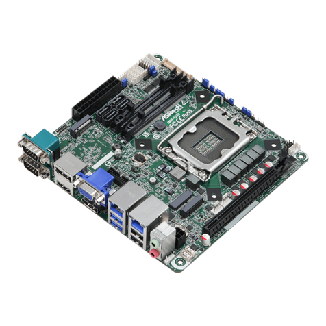
ank you for purchasing ASRockInd IMB-1239-WV / IMB-1240-WV / IMB-X1240-WV
motherboard, a reliable motherboard produced under ASRockInd’s consistently stringent
quality control. It delivers excellent performance with robust design conforming to ASRock-
Ind’s commitment to quality and endurance.
In this manual, chapter 1 and 2 contain introduction of the motherboard and step-by-step
guide to the hardware installation. Chapter 3 contains the conguration guide to BIOS setup.
Because the motherboard specications and the BIOS soware might be updated, the
content of this manual will be subject to change without notice. In case any modica-
tions of this manual occur, the updated version will be available on ASRockInd website
without further notice. You may nd the latest CPU support lists on ASRockInd web-
site as well.
ASRockInd website https://www.asrockind.com/en-gb/IMB-1239-WV
https://www.asrockind.com/en-gb/IMB-1240-WV
https://www.asrockind.com/en-gb/IMB-X1240-WV
If you require technical support related to this motherboard, please visit our website for
specic information about the model you are using.
https://www.asrockind.com/technical-support
1.1 Package Contents
ASRockInd IMB-1239-WV / IMB-1240-WV / IMB-X1240-WV Motherboard (Mini-ITX
(6.7-in x 6.7-in x 1.5-in, 17.0 cm x 17.0 cm x 2.5 cm)
IMB-1239-WV IMB-1240-WV / IMB-X1240-WV
Gi Package
1 x I/O Shield
1 x I/O Shield THIN
3 x SCREW M2*2, D=5
1 x SATA Power Cable
2 x COM Cable
2 x SATA Cable
1 x I/O Shield
1 x I/O Shield THIN
4 x SCREW M2*2, D=5
1 x SATA Power Cable
2 x COM Cable
2 x SATA Cable
Bulk Package
1 x I/O Shield
1 x I/O Shield THIN
3 x SCREW M2*2, D=5
1 x I/O Shield
1 x I/O Shield THIN
4 x SCREW M2*2, D=5
2
1.2 Specications
Form Factor Dimensions
(LxWxH)
Mini-ITX (6.7-in x 6.7-in x 1.5-in, 17.0 cm x 17.0 cm
x 2.5 cm)
Processor
System
CPU
Intel® 14th/13th/12th Gen (Raptor Lake-S Refresh/
Raptor Lake-S/Alder Lake-S) Core™ Processors, up
to 65W
Chipset Intel® H610
Socket LGA1700
BIOS AMI SPI 256 Mbit
Memory
Technology
Dual Channel DDR5 4800/5600 MHz*
*Actual memory frequency depends on the CPU
types and DRAM modules, for more information
refer to https://www.asrockind.com/en-gb/index.
php?route=newsblog/faq&faq_id=90 technical FAQ
*If motherboard ambient temperature is over 55ºC,
the memory thermal solution should be added to
avoid thermal issue.
Capacity 64 GB (32 GB per DIMM)
Socket 2 x 262-pin SO-DIMM
Graphics
Controller Intel® UHD Graphics
HDMI HDMI 2.0b
Max resolution up to 4096x2160@60Hz
DisplayPort DisplayPort 1.4a, DP++
Max resolution up to 4096x2160@60Hz
LVDS Dual channel 24 bit up to 1920x1200@60Hz
eDP eDP1.4b
Max resolution up to 4096x2160@60Hz
MultiDisplay Triple Display
Expansion
Slot
PCIe 1 x PCIe x16 (Gen5)
M.2
1 x M.2 (Key E, 2230) with PCIe x1, USB 2.0 and
CNVi for Wireless
1 x M.2 (Key B, 3042/3052) with PCIe x1, USB 3.2
Gen1, USB 2.0 and SIM for 4G/5G
SIM Socket 1 x Socket connected to M.2 Key B
Audio Interface Realtek ALC662, High Denition Audio. Line-out,
Mic-in
Ethernet
Controller/
Speed
LAN1: Intel® I226V with 10/100/1000/2500 Mbps
LAN2: Intel® I219V with 10/100/1000 Mbps
Controller 2 x RJ-45
• IMB-1239-WV
3
IMB-1239-WV_IMB-1240-WV_IMB-X1240-WV
Rear I/O
HDMI 2 x HDMI 2.0b
DisplayPort 1 x DP 1.4a++
Ethernet 1 x 2.5 Gigabit LAN
1 x 1 Gigabit LAN
USB 2 x USB 3.2 (Gen2)
2 x USB 2.0
Audio 2 (Mic-in, Line-out)
Internal
Connector
USB 1 x USB 3.2 Gen1 (1 x USB 3.2 header)
3 x USB 2.0 (1 x 2.54 pitch header)
COM COM1, COM3 (RS-232/422/485)
GPIO 4 x GPI, 4 x GPO
LVDS 1
eDP 1
SATA PWR
Output 1
Speaker
Header 1
Storage M.2 1 x M.2 (Key M, 2242/2280) with PCIe Gen3 x4
for SSD
SATA 2 x SATA3 (6Gb/s)
Security TPM TPM 2.0 onboard IC
Watchdog
Timer
Output From Super I/O to drag RESETCON#
Interval 256 Segments, 0, 1, 2, ...255 Sec
Power
Requirements
Input PWR 12~28V DC-In with 4-pin wafer PWR cable or
DC Jack (Screw type)
Power On
AT/ATX supported
- AT : Directly PWR on as po wer input ready
- ATX : Press button to PWR on aer po wer
input ready
Environment
Operating
Temperature 0ºC ~ 70ºC
Storage
Temperature -40° C ~ 85° C
Operating
Humidity 5% ~ 90%
Storage
Humidity 5% ~ 90%
4
Form Factor Dimensions
(LxWxH)
Mini-ITX (6.7-in x 6.7-in x 1.5-in, 17.0 cm x 17.0 cm
x 2.5 cm
Processor
System
CPU
Intel® 14th/13th/12th Gen (Raptor Lake-S Refresh/
Raptor Lake-S/Alder Lake-S) Core™ Processors, up
to 65W
Chipset Intel® Q670
Socket LGA1700
BIOS AMI SPI 256 Mbit
Memory
Technology
Dual Channel DDR5 4800/5600 MHz*
*Actual memory frequency depends on the CPU
types and DRAM modules, for more information
refer to https://www.asrockind.com/en-gb/index.
php?route=newsblog/faq&faq_id=90 technical FAQ
*If motherboard ambient temperature is over 55ºC,
the memory thermal solution should be added to
avoid thermal issue.
Capacity 64 GB (32 GB per DIMM)
Socket 2 x 262-pin SO-DIMM
Graphics
Controller Intel® UHD Graphics
HDMI HDMI 2.0b
Max resolution up to 4096x2160@60Hz
DisplayPort DisplayPort 1.4a, DP++
Max resolution up to 4096x2160@60Hz
LVDS Dual channel 24 bit up to 1920x1200@60Hz
eDP eDP1.4b
Max resolution up to 4096x2160@60Hz
MultiDisplay Quad Display
Expansion
Slot
PCIe 1 x PCIe x16 (Gen5, Support riser card x8/x8)
M.2
1 x M.2 (Key E, 2230) with PCIe x1, USB 2.0 and
CNVi for Wireless
1 x M.2 (Key B, 3042/3052) with PCIe x1, USB 3.2
Gen1, USB 2.0 and SIM for 4G/5G
SIM Socket 1 x Socket connected to M.2 Key B
Audio Interface Realtek ALC897, High Denition Audio. Line-out,
Mic-in
• IMB-1240-WV
5
IMB-1239-WV_IMB-1240-WV_IMB-X1240-WV
Ethernet
Controller/
Speed
LAN1: Intel® I226V with 10/100/1000/2500 Mbps
LAN2: Intel® I219LM with 10/100/1000 Mbps,
supports vPro
Controller 2 x RJ-45
Rear I/O
HDMI 2 x HDMI 2.0b
DisplayPort 1 x DP 1.4a++
Ethernet 1 x 2.5 Gigabit LAN
1 x 1 Gigabit LAN
USB 4 x USB 3.2 (Gen2)
Audio 2 (Mic-in, Line-out)
Internal
Connector
USB 2 x USB 3.2 Gen1 (1 x USB 3.2 header)
4 x USB 2.0 (2 x 2.54 pitch header)
COM COM1, COM3 (RS-232/422/485)
GPIO 4 x GPI, 4 x GPO
LVDS 1
eDP 1
SATA PWR
Output 1
Speaker
Header 1
Storage
M.2
1 x M.2 (Key M, 2242/2280) with PCIe Gen4 x4
for SSD
1 x M.2 (KeyM, 2242) with PCIe Gen4 x4 and
SATA3 for SSD*
*Recommend using M2X4-SATA-4P module to
support extra 4 SATA ports (supported by special
BIOS)
SATA 2 x SATA3 (6Gb/s)
RAID
Intel® VMD RAID 0/1
**supported by identical interface (PCIe or SATA)
PCIe interface: M.2 Key B + M.2 Key M1/2 or
2*M.2 Key M
SATA interface: SATA port
Security TPM TPM 2.0 onboard IC
Watchdog
Timer
Output From Super I/O to drag RESETCON#
Interval 256 Segments, 0, 1, 2, ...255 Sec
6
Power
Requirements
Input PWR 12~28V DC-In with 4-pin wafer PWR cable or DC
Jack (Screw type)
Power On
AT/ATX Supported
- AT : Directly PWR on as power input ready
- ATX : Press button to PWR on aer power input
ready
Environment
Operating
Temperature 0ºC ~ 70ºC
Storage
Temperature -40° C ~ 85° C
Operating
Humidity 5% ~ 90%
Storage
Humidity 5% ~ 90%
7
IMB-1239-WV_IMB-1240-WV_IMB-X1240-WV
• IMB-X1240-WV
Form Factor Dimensions
(LxWxH)
Mini-ITX (6.7-in x 6.7-in x 1.5-in, 17.0 cm x 17.0 cm
x 2.5 cm)
Processor
System
CPU
Intel® 14th/13th/12th Gen (Raptor Lake-S Refresh/
Raptor Lake-S/Alder Lake-S) Core™ Processors, up
to 65W
Chipset Intel® W680
Socket LGA1700
BIOS AMI SPI 256 Mbit
Memory
Technology
Dual Channel ECC/non-ECC DDR5 4800/5600
MHz*
*Actual memory frequency depends on the CPU
types and DRAM modules, for more information
refer to https://www.asrockind.com/en-gb/index.
php?route=newsblog/faq&faq_id=90 technical FAQ
*If motherboard ambient temperature is over 55ºC,
the memory thermal solution should be added to
avoid thermal issue.
Capacity 64 GB (32 GB per DIMM)
Socket 2 x 262-pin SO-DIMM
Graphics
Controller Intel® UHD Graphics
HDMI HDMI 2.0b
Max resolution up to 4096x2160@60Hz
DisplayPort DisplayPort 1.4a, DP++
Max resolution up to 4096x2160@60Hz
LVDS Dual channel 24 bit up to 1920x1200@60Hz
eDP eDP1.4b
Max resolution up to 4096x2160@60Hz
MultiDisplay Quad Display
Expansion
Slot
PCIe 1 x PCIe x16 (Gen5, support riser card x8/x8)
M.2
1 x M.2 (Key E, 2230) with PCIe x1, USB 2.0 and
CNVi for Wireless
1 x M.2 (Key B, 3042/3052) with PCIe x1, USB 3.2
Gen1, USB 2.0 and SIM for 4G/5G
SIM Socket 1 x Socket connected to M.2 Key B
Audio Interface Realtek ALC897, High Denition Audio. Line-out,
Mic-in
8
Ethernet
Controller/
Speed
LAN1: Intel® I226V with 10/100/1000/2500 Mbps
LAN2: Intel® I219LM with 10/100/1000 Mbps,
supports vPro
Controller 2 x RJ-45
Rear I/O
HDMI 2 x HDMI 2.0b
DisplayPort 1 x DP 1.4a++
Ethernet 1 x 2.5 Gigabit LAN
1 x 1 Gigabit LAN
USB 4 x USB 3.2 (Gen2)
Audio 2 (Mic-in, Line-out)
Internal
Connector
USB 2 x USB 3.2 Gen1 (1 x USB 3.2 header)
4 x USB 2.0 (2 x 2.54 pitch header)
COM COM1, COM3 (RS-232/422/485)
GPIO 4 x GPI, 4 x GPO
LVDS 1
eDP 1
SATA PWR
Output 1
Speaker Header 1
Storage
M.2
1 x M.2 (Key M, 2242/2280) with PCIe Gen4 x4
for SSD
1 x M.2 (KeyM, 2242) with PCIe Gen4 x4 and
SATA3 for SSD*
*Recommend using M2X4-SATA-4P module to
support extra 4 SATA ports (supported by special
BIOS)
SATA 2 x SATA3 (6Gb/s)
RAID
Intel® VMD RAID 0/1
**supported by identical interface (PCIe or
SATA)
PCIe interface: M.2 Key B + M.2 Key M1/2 or
2*M.2 Key M
SATA interface: SATA port
Security TPM TPM 2.0 onboard IC
Watchdog
Timer
Output From Super I/O to drag RESETCON#
Interval 256 Segments, 0, 1, 2, ...255 Sec
9
IMB-1239-WV_IMB-1240-WV_IMB-X1240-WV
Power
Requirements
Input PWR 12~28V DC-In with 4-pin wafer PWR cable or
DC Jack (Screw type)
Power On
AT/ATX Supported
- AT : Directly PWR on as power input ready
- ATX : Press button to PWR on aer power
input ready
Environment
Operating
Temperature 0ºC ~ 70ºC
Storage
Temperature -40° C ~ 85° C
Operating
Humidity 5% ~ 90%
Storage
Humidity 5% ~ 90%
10
1.3 Motherboard Layout
Industrial
IMB-1239-WV
9
7
2
13
45
68
16 (*Backside:
EDP1)
17
15
18
21
22
26
27
28
32
31 29
24
25
23
19
Mic In
1
HD_AUDIO1
PCIE1
USB 3.2 Gen2
T: USB3_2
B: USB3_1
Line Out
SATA3_6 SATA3_5
HDMI2
LAN1
SPDIF1
1
M2_KEYM1
COM1
DC_JACK1
USB3_4_9
TO_UPS1
1
M2_KEYE1
PWR_ADAPTER
1
BLT_V OL1 BLT_PWR1
1
1
COM3
36
35
33
20
BIOS
ROM
USB2_5_6
M2_B1
EDP_BLT_PWR2
1
1
1
JGPIO1
JGPIO_SET1
JGPIO_PWR1
BAT1 SATA_PWR1
1
1
1
1
1
1
1
1
CI1_2
CLRMOS1
1
PLED PWRBTN
HDLED RESET
1
PANEL1
SMBUS_TEST1
11
CPU_FAN1
C_FAN1HA
1
1
1
LAN2
1
USB2.0
T: USB3_8
B: USB3_7
DP1
HDMI1
PWR_BAT1_SIO_AT1
AT_TEST1_PCIE_PWR1
1
1
14
30
11
10 12 13
PWR_COM1
BKT_PWR1DACC1
HEATER1
11
1111
DDR _B15
DDR _A15
ESPI1
PNL_PWR1
1
LVDS1
1
11
1
34
SPEAKER1
1
DC_4PIN1
• IMB-1239-WV
11
IMB-1239-WV_IMB-1240-WV_IMB-X1240-WV
1 : ESPI Header (ESPI1)
2 : M.2 Key-B Socket (M2_B1)
3 : Battery Connector (BAT1)
4 : SATA Power Output Connector (SATA_PWR1)
5 : SATA3 Connectors (SATA3_5, SATA3_6)
6 : Digital Input/Output Power Select (JGPIO_PWR1)
7 : Digital Input/Output Default Value Setting (JGPIO_SET1)
8 : Digital Input/Output Pin Header (JGPIO1)
9 : COM Port Headers (COM1, COM3) (RS232/422/485)
10 : COM Port PWR Setting Jumpers PWR_COM1 (For COM Port1)
11 : HEATER1 Header (HEATER1)
12 : Backlight Power Select (LCD_BLT_VCC) (BKT_PWR1)
13 : DACC Jumper (DACC1)
14 : Backlight Volume Control (BLT_VOL1)
15 : Inverter Power Control Wafer (BLT_PWR1)
16 : LVDS Panel Connector (LVDS1) (eDP Connector (on the Backside of PCB))
17 : Panel Power Select (LCD_VCC) (PNL_PWR1)
18 : Inverter Power Control Wafer (EDP_BLT_PWR2)
19 : Chassis Intrusion Header (CI1_2)
20 : Clear CMOS Header (CLRMOS1)
21 : PWR_BAT1_SIO_AT1
22 : AT_TEST1_PCIE_PWR1
23 : System Panel Header (PANEL1)
24 : SMBUS_TEST1
25 : CPU FAN Connector (+12V) (CPU_FAN1)
26 : Chassis FAN Connector (+12V) (CHA_FAN1)
27 : Power Adapter (PWR_ADAPTER)
28 : M.2 Key-M Socket (M2_KEYM1)
29 : M.2 Key-E Socket (M2_KEYE1)
30 : 4-pin ATX PWR Connector (DC_4PIN1)
31 : 2-pin UPS Module Power Input Connector (TO_UPS1)
32 : SPDIF Header (SPDIF1)
33 : Front Panel Audio Header (HD_AUDIO1)
34 : 3W Audio AMP Output Wafer (SPEAKER1)
35 : USB 2.0 Headers (USB2_5_6)
36 : USB 3.2 Gen1 Header (USB3_4_9)
12
• IMB-1240-WV / IMB-X1240-WV
Industrial
12
11
10
18
3
24
56
79
17 (*Backside:
EDP1)
13 14
18
16
19
22
23
27
28
29
33
32 30
25
26
24
20
Mic In
HD_AUDIO1
PCIE1
USB 3.2 Gen2
T: USB3_2
B: USB3_1
Line Out
DC_4PIN1
SATA3_6 SATA3_5
SPEAKER1
1
HDMI2
LAN1
SPDIF1
1
DDR _B15
DDR _A15
M2_KEYM1
COM1
PWR_COM1
DC_JACK1
USB3_4_9
TO_UPS1
1
M2_KEYE1
M2_KEYM2
PWR_ADAPTER
1
BLT_V OL1 BLT_PWR1
PNL_PWR1
1
BKT_PWR1
COM3
37
36
34
35
21
USB2_5_6
M2_B1
EDP_BLT_PWR2
USB2_10_11
DACC1
HEATER1
11
1
1
1
JGPIO1
JGPIO_SET1
JGPIO_PWR1
BAT1 SATA_PWR1
1
1
1
1
1
1
1
1
1
CI1_2
CLRMOS1
1
PLED PWRBTN
HDLED RESET
1
PANEL1
SMBUS_TEST1
11
CPU_FAN1
C_FAN1HA
1
1
1
11
LAN2
1
USB 3.2 Gen2
T: USB3_8
B: USB3_7
DP1
HDMI1
PWR_BAT1_SIO_AT1
AT_TEST1_PCIE_PWR1
1
1
15
31
1111
11
1
ESPI1
LVDS1
BIOS
ROM
1
1
1
13
IMB-1239-WV_IMB-1240-WV_IMB-X1240-WV
1 : M.2 Key-M Socket (M2_KEYM2)
2 : ESPI Header (ESPI1)
3 : M.2 Key-B Socket (M2_B1)
4 : Battery Connector (BAT1)
5 : SATA Power Output Connector (SATA_PWR1)
6 : SATA3 Connectors (SATA3_5, SATA3_6)
7 : Digital Input/Output Power Select (JGPIO_PWR1)
8 : Digital Input/Output Default Value Setting (JGPIO_SET1)
9 : Digital Input/Output Pin Header (JGPIO1)
10 : COM Port Headers (COM1, COM3) (RS232/422/485)
11 : COM Port PWR Setting Jumpers PWR_COM1 (For COM Port1)
12 : HEATER1 Header (HEATER1)
13 : Backlight Power Select (LCD_BLT_VCC) (BKT_PWR1)
14 : DACC Jumper (DACC1)
15 : Backlight Volume Control (BLT_VOL1)
16 : Inverter Power Control Wafer (BLT_PWR1)
17 : LVDS Panel Connector (LVDS1) (eDP Connector (on the Backside of PCB))
18 : Panel Power Select (LCD_VCC) (PNL_PWR1)
19 : Inverter Power Control Wafer (EDP_BLT_PWR2)
20 : Chassis Intrusion Header (CI1_2)
21 : Clear CMOS Header (CLRMOS1)
22 : PWR_BAT1_SIO_AT1
23 : AT_TEST1_PCIE_PWR1
24 : System Panel Header (PANEL1)
25 : SMBUS_TEST1
26 : CPU FAN Connector (+12V) (CPU_FAN1)
27 : Chassis FAN Connector (+12V) (CHA_FAN1)
28 : Power Adapter (PWR_ADAPTER)
29 : M.2 Key-M Socket (M2_KEYM1)
30 : M.2 Key-E Socket (M2_KEYE1)
31 : 4-pin ATX PWR Connector (DC_4PIN1)
32 : 2-pin UPS Module Power Input Connector (TO_UPS1)
33 : SPDIF Header (SPDIF1)
34 : Front Panel Audio Header (HD_AUDIO1)
35 : 3W Audio AMP Output Wafer (SPEAKER1)
36 : USB 2.0 Headers (USB2_5_6, USB2_10_11)
37 : USB 3.2 Gen1 Header (USB3_4_9)
14
1.4 I/O Panel
6
124
35798 10
1 USB 3.2 Gen2 Ports (USB3_1_2)
Top: USB3_2
Bottom: USB3_1
2 IMB-1239-WV:
USB 2.0 Ports (USB3_7_8)
IMB-1240-WV / IMB-X1240-WV:
USB 3.2 Gen2 (USB3_7_8)
Top: USB3_8
Bottom: USB3_7
3 HDMI Port (HDMI1)
4 DisplayPort (DP1)
5 HDMI Port (HDMI2)
6 RJ45 LAN Port (LAN2)**
7 RJ45 LAN Port (LAN1)*
8 Audio Output: Green - Line Out
9 Audio Output: Pink - Mic In
10 DC JACK (DC_JACK1)
• IMB-1239-WV
• IMB-1240-WV / IMB-X1240-WV
6
124
35798 10
15
IMB-1239-WV_IMB-1240-WV_IMB-X1240-WV
ACT/LINK
LED
SPEED
LED
LAN1 Port
Status Description
O 10Mbps connection
Orange 100Mbps/1Gbps connection
Green 2.5Gbps connection
Activity/Link LED SPEED LED
Status Description
O No Link
Blinking Data Activity
On Link
* ere are two LED next to the LAN1 port. Please refer to the table below for the LAN1 port LED indica-
tions.
LAN1 Port LED Indications
ACT/LINK
LED
SPEED
LED
LAN2 Port
Status Description
O 10Mbps connection
Orange 100Mbps connection
Green 1Gbp connection
Activity/Link LED SPEED LED
Status Description
O No Link
Blinking Data Activity
On Link
** ere are two LED next to the LAN2 port. Please refer to the table below for the LAN2 port LED indica-
tions.
LAN2 Port LED Indications

This manual suits for next models

2

Other ASRock Industrial Motherboard manuals
ASRock Industrial SOM-P104 User manual

ASRock Industrial

ASRock Industrial SOM-P104 User manual

ASRock Industrial IMB-1711 User manual

ASRock Industrial

ASRock Industrial IMB-1711 User manual

ASRock Industrial IMB-1004 User manual

ASRock Industrial

ASRock Industrial IMB-1004 User manual

ASRock Industrial IMB-157 User manual

ASRock Industrial

ASRock Industrial IMB-157 User manual

ASRock Industrial IMB-1235 Service manual

ASRock Industrial

ASRock Industrial IMB-1235 Service manual

ASRock Industrial SBC-371 User manual

ASRock Industrial

ASRock Industrial SBC-371 User manual

ASRock Industrial IMB-X1314 Service manual

ASRock Industrial

ASRock Industrial IMB-X1314 Service manual

ASRock Industrial IMB-1712 User manual

ASRock Industrial

ASRock Industrial IMB-1712 User manual

ASRock Industrial IMB-V2000 User manual

ASRock Industrial

ASRock Industrial IMB-V2000 User manual

ASRock Industrial SBC-370 User manual

ASRock Industrial

ASRock Industrial SBC-370 User manual

ASRock Industrial IMB-R1000 User manual

ASRock Industrial

ASRock Industrial IMB-R1000 User manual

ASRock Industrial NUC-1360P/D5 User manual

ASRock Industrial

ASRock Industrial NUC-1360P/D5 User manual

ASRock Industrial N3710-NUC IPC User manual

ASRock Industrial

ASRock Industrial N3710-NUC IPC User manual

ASRock Industrial 4X4-7840U-1U User manual

ASRock Industrial

ASRock Industrial 4X4-7840U-1U User manual

ASRock Industrial NUC-155H User manual
ASRock Industrial

ASRock Industrial NUC-155H User manual

ASRock Industrial IMB-1713 Service manual

ASRock Industrial

ASRock Industrial IMB-1713 Service manual

ASRock Industrial IMB-1235 User manual

ASRock Industrial

ASRock Industrial IMB-1235 User manual

ASRock Industrial N3160-NUC IPC User manual

ASRock Industrial

ASRock Industrial N3160-NUC IPC User manual

ASRock Industrial IMB-1231 User manual

ASRock Industrial

ASRock Industrial IMB-1231 User manual

ASRock Industrial IMB-1314 Service manual

ASRock Industrial

ASRock Industrial IMB-1314 Service manual

ASRock Industrial IMB-X1314 Service manual

ASRock Industrial

ASRock Industrial IMB-X1314 Service manual

ASRock Industrial IMB-151D-WF User manual

ASRock Industrial

ASRock Industrial IMB-151D-WF User manual

ASRock Industrial IMB-X1314 User manual

ASRock Industrial

ASRock Industrial IMB-X1314 User manual

ASRock Industrial IMB-X1316 User manual

ASRock Industrial

ASRock Industrial IMB-X1316 User manual

Popular Motherboard manuals by other brands

Digilent Cmod S6 Reference manual

Digilent

Digilent Cmod S6 Reference manual

Silicon Laboratories Si5381/82 user guide

Silicon Laboratories

Silicon Laboratories Si5381/82 user guide

ST STEVAL-MKI019V1 user manual

ST

ST STEVAL-MKI019V1 user manual

Advantech AIMB-252 user manual

Advantech

Advantech AIMB-252 user manual

IEI Technology IMBA-690AM2 user manual

IEI Technology

IEI Technology IMBA-690AM2 user manual

ECS H61H2-M5 manual

ECS

ECS H61H2-M5 manual

Gigabyte GA-8ST800 user manual

Gigabyte

Gigabyte GA-8ST800 user manual

Meilhaus Electronic ME-5004 manual

Meilhaus Electronic

Meilhaus Electronic ME-5004 manual

Xilinx Arty A7 Reference manual

Xilinx

Xilinx Arty A7 Reference manual

HP Irvine user manual

HP

HP Irvine user manual

EVOC EC7-1813CLD2NA SERIES user guide

EVOC

EVOC EC7-1813CLD2NA SERIES user guide

Foxconn WinFast 6150K8M Series user manual

Foxconn

Foxconn WinFast 6150K8M Series user manual

Asus MEZ-M user manual

Asus

Asus MEZ-M user manual

Asus B250 MINING EXPERT manual

Asus

Asus B250 MINING EXPERT manual

Asus X99-A II user guide

Asus

Asus X99-A II user guide

Zida T530B-S manual

Zida

Zida T530B-S manual

MSI B350 GAMING quick start

MSI

MSI B350 GAMING quick start

ASROCK H67M-GE/THW owner's manual

ASROCK

ASROCK H67M-GE/THW owner's manual

manuals.online logo
manuals.online logoBrands
  • About & Mission
  • Contact us
  • Privacy Policy
  • Terms and Conditions

Copyright 2025 Manuals.Online. All Rights Reserved.