GTC
■
Service Manual
Content
1.EQUIPMENT NEED ..................................................................................................................................... 3
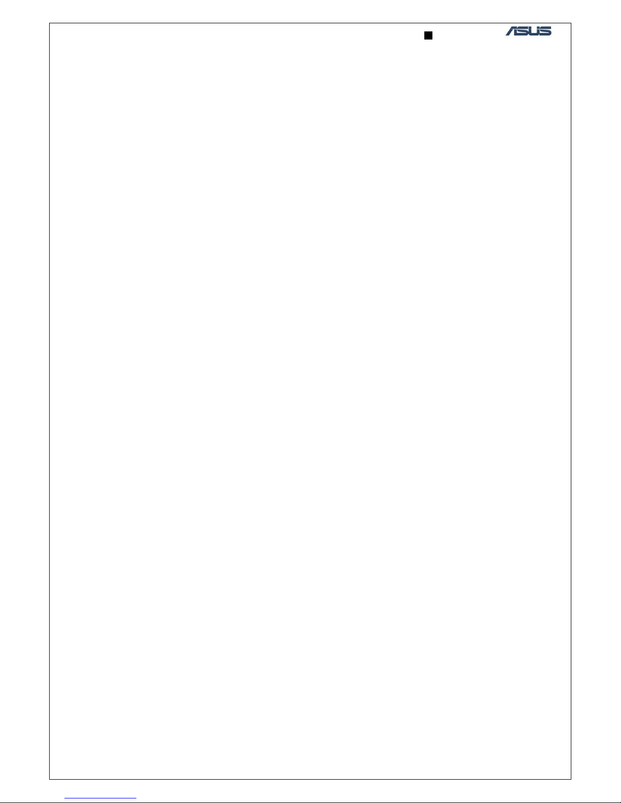
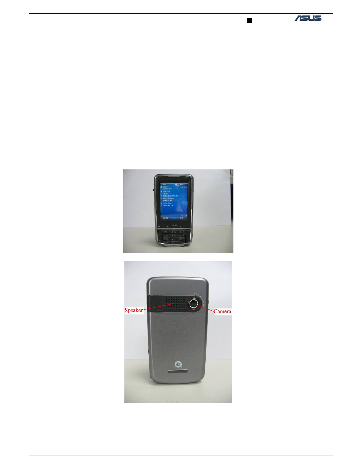
2. OUTLINE AND SIDE KEYS ....................................................................................................................... 3
3.INTRODUCTION .......................................................................................................................................... 5
3.1
B
LOCK DIAGRAM
........................................................................................................................................ 5
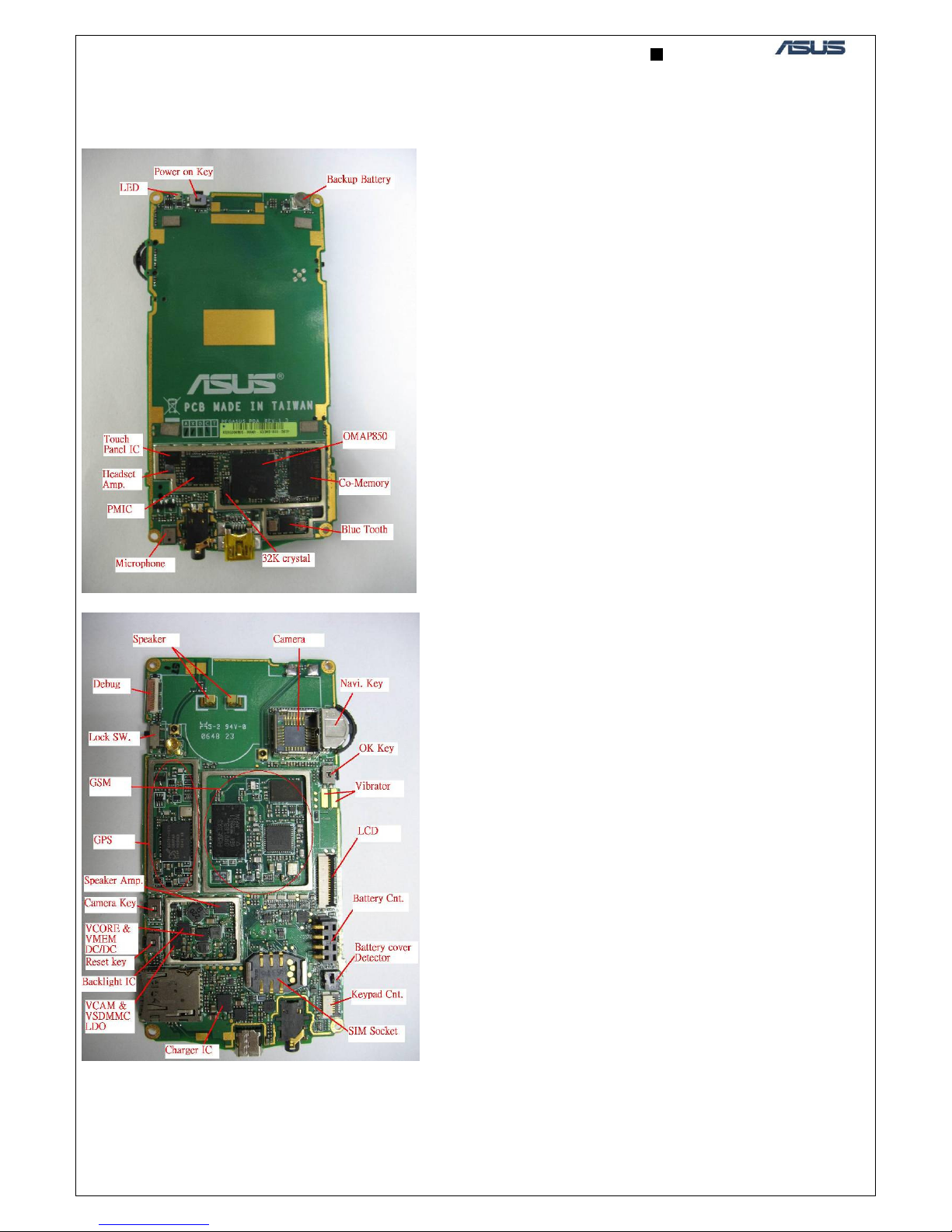
3.2
M
AIN COMPONENTS AND PLACEMENT
......................................................................................................... 6
4.﹒
﹒﹒
﹒MMI TEST PROGRAM............................................................................................................................ 7
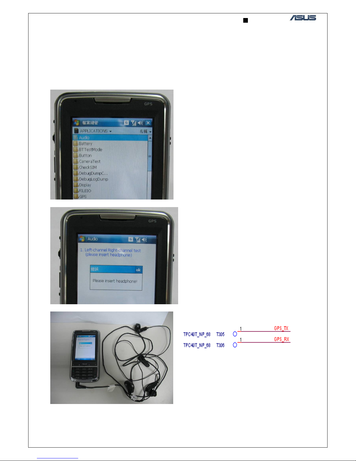
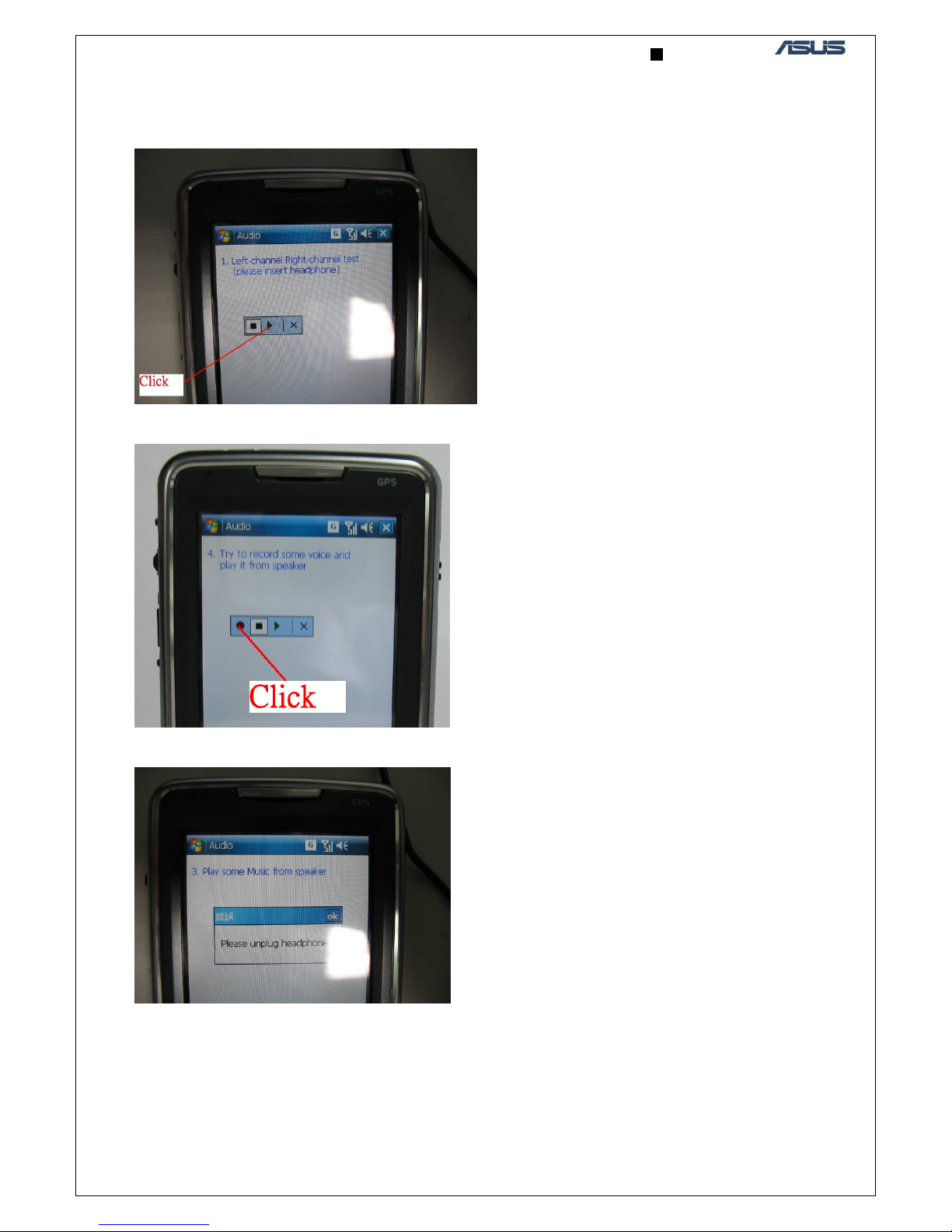
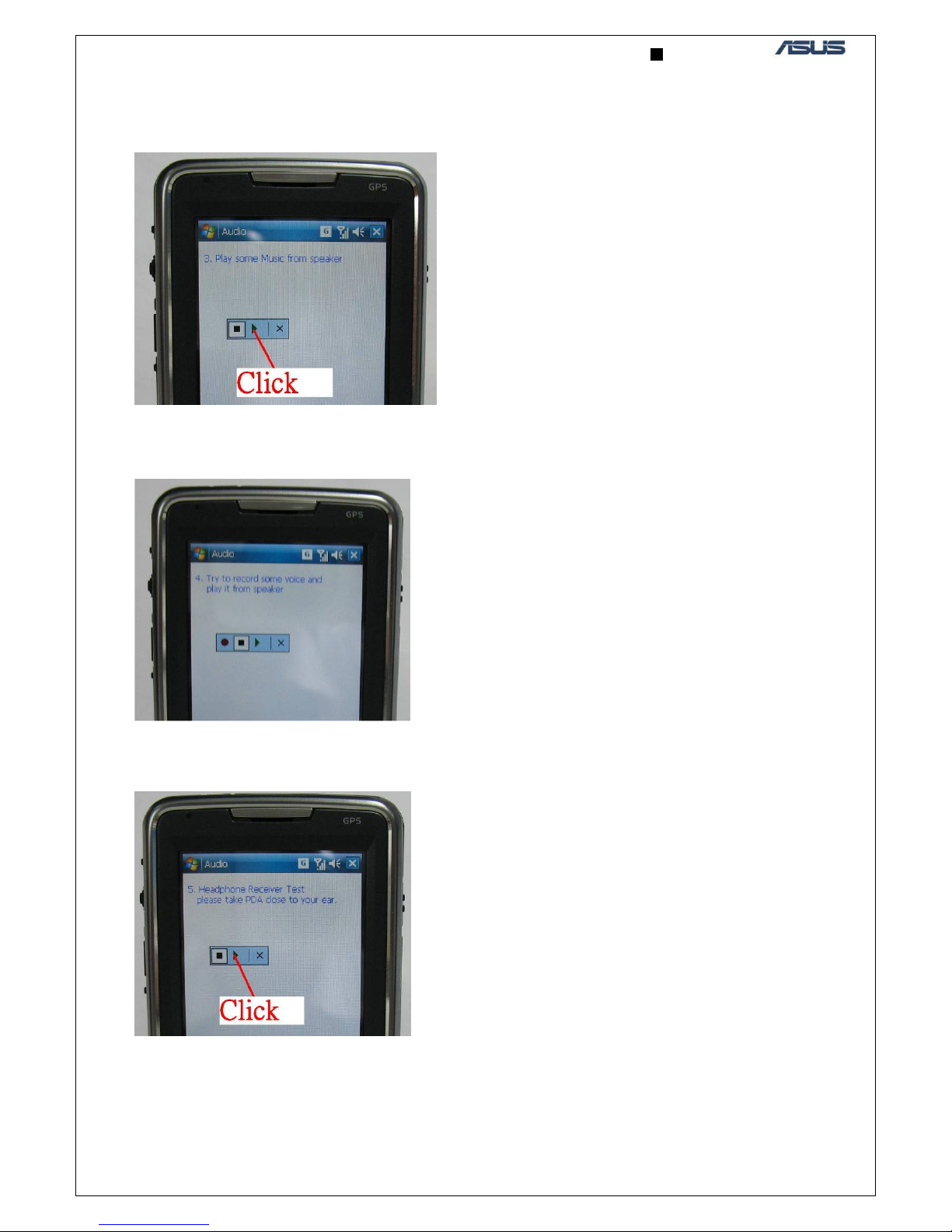
4.1
A
UDIO TEST
(
INCLUDING HEADSET
,
HANDSET AND SPEAKER
)...................................................................... 7
4.2
H
EADSET TEST
: ........................................................................................................................................... 8
4.3
S
PEAKER TEST
:........................................................................................................................................ 9
4.4
M
ICROPHONE TEST
:................................................................................................................................. 9
4.5
R
ECEIVER TEST
: .......................................................................................................................................... 9
4.6
B
UTTON
/
KEYPAD TEST
............................................................................................................................ 10
4.8
LED
TEST
................................................................................................................................................. 11
4.9
V
IBRATOR TEST
......................................................................................................................................... 12
4.10
TMC
TEST
............................................................................................................................................ 12
5.TROUBLE SHOOTING.............................................................................................................................. 14
5.1
S
YSTEM CAN
’
T POWER ON
........................................................................................................................ 14
5.2
T
OUCH PANEL
........................................................................................................................................... 19
5.3.1﹒Headset:......................................................................................................................................... 21
5.3.3﹒Handset: ........................................................................................................................................ 23
5.4
B
ATTERY CHARGING
................................................................................................................................. 24
5.5
B
UTTON
/
KEYPAD TEST
.............................................................................................................................. 26
5.7
C
AMERA
................................................................................................................................................... 29
5.8
LCD ......................................................................................................................................................... 31
5.9
LED.......................................................................................................................................................... 35
5.10
V
IBRATOR
............................................................................................................................................... 36
5.11
M
ICRO
SD
CARD
..................................................................................................................................... 37
5.12
TMC....................................................................................................................................................... 38
6. RF PURPOSE:............................................................................................................................................. 40
7.EQUIPMENTS ............................................................................................................................................. 40
7.1
S
OFTWARE REQUIREMENT
:........................................................................................................................ 40
7.2
H
ARDWARE REQUIREMENT
: ...................................................................................................................... 40
8. TEST POINTS ............................................................................................................................................. 41
9. COMPONENTS DISPLACEMENT ......................................................................................................... 44
10. THE SETUPS FOR THE MOBILE HARDWARE TESTING AND TESTING RESULTS .............. 48
11. RF BOARD LEVEL EXAMINATION PROCEDURE.......................................................................... 81
11.1
IF THE
PCB
COULD NOT BOOT
.................................................................................................................. 81
11.2
GSM
APC
FAIL
....................................................................................................................................... 82
11.3
AFC-VISA
FAIL
...................................................................................................................................... 83
11.4
E
DGE
APC
FAIL
...................................................................................................................................... 83