ASUS T500 MB Service Manual
Content
I. Baseband Troubleshooting Guide
1. System Block Diagram
2. Power Block Diagram
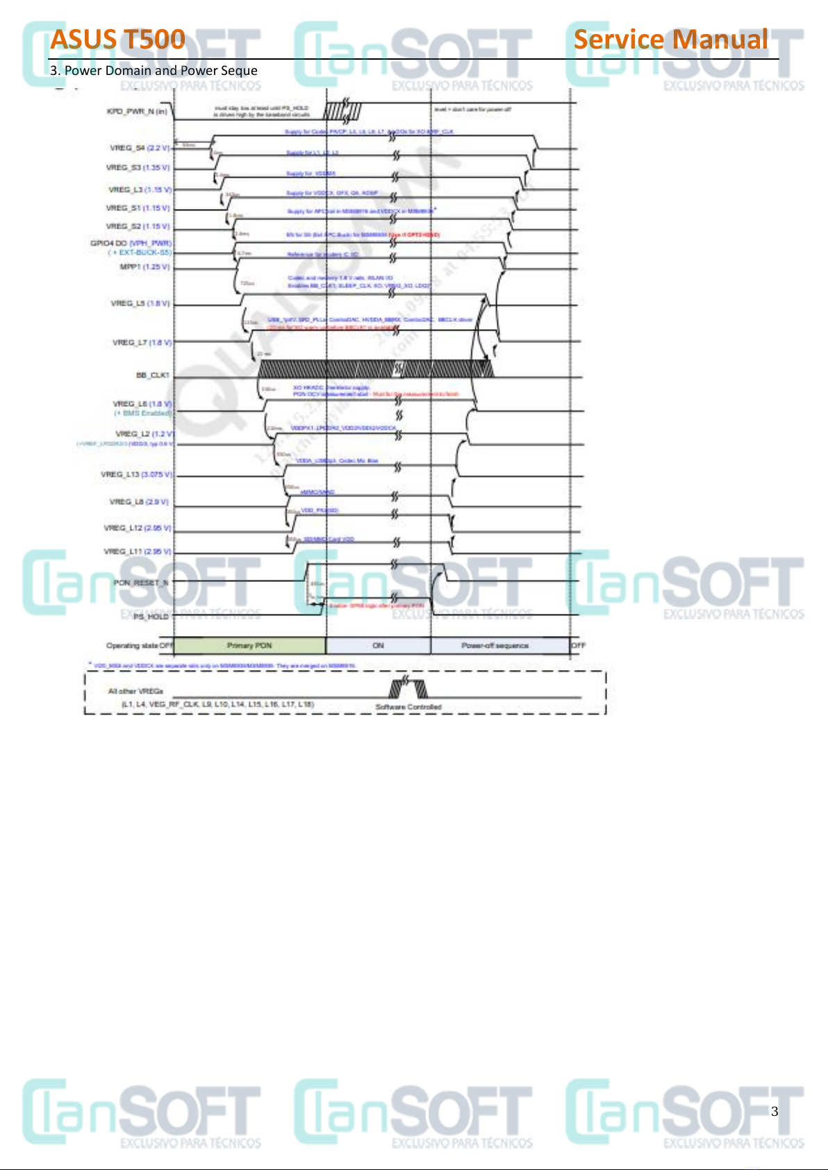
3. Power Domain and Power Sequence
II. MB Trouble Shooting Guide
I. Baseband Troubleshooting Guide ...............................................................................................................................1
II. MB Trouble Shooting Guide.......................................................................................................................................1
1. Outline and Component Introduction.........................................................................................................................4
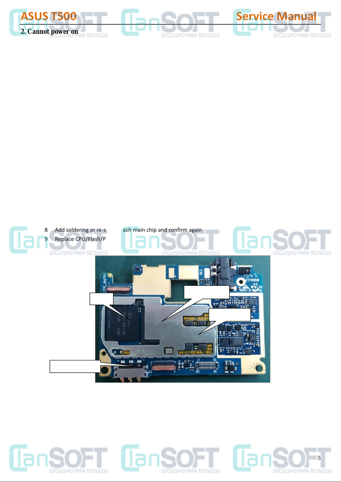
2. Cannot power on...................................................................................................................................................5
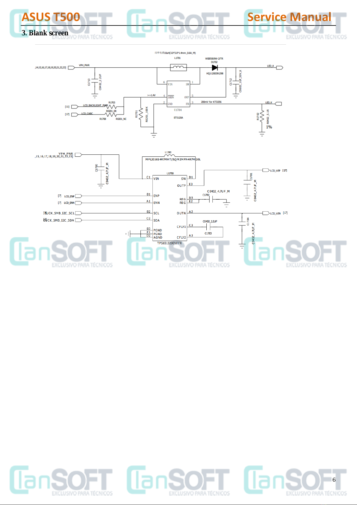
3. Blank screen..........................................................................................................................................................6
4. LCD display failure ................................................................................................................................................7
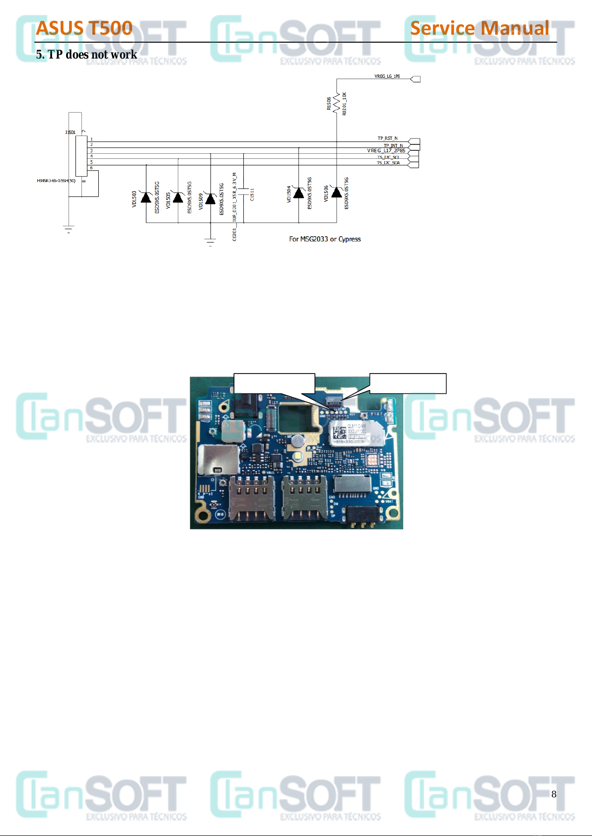
5. TP does not work...................................................................................................................................................8
6. Light / Distance sensor failure...............................................................................................................................9
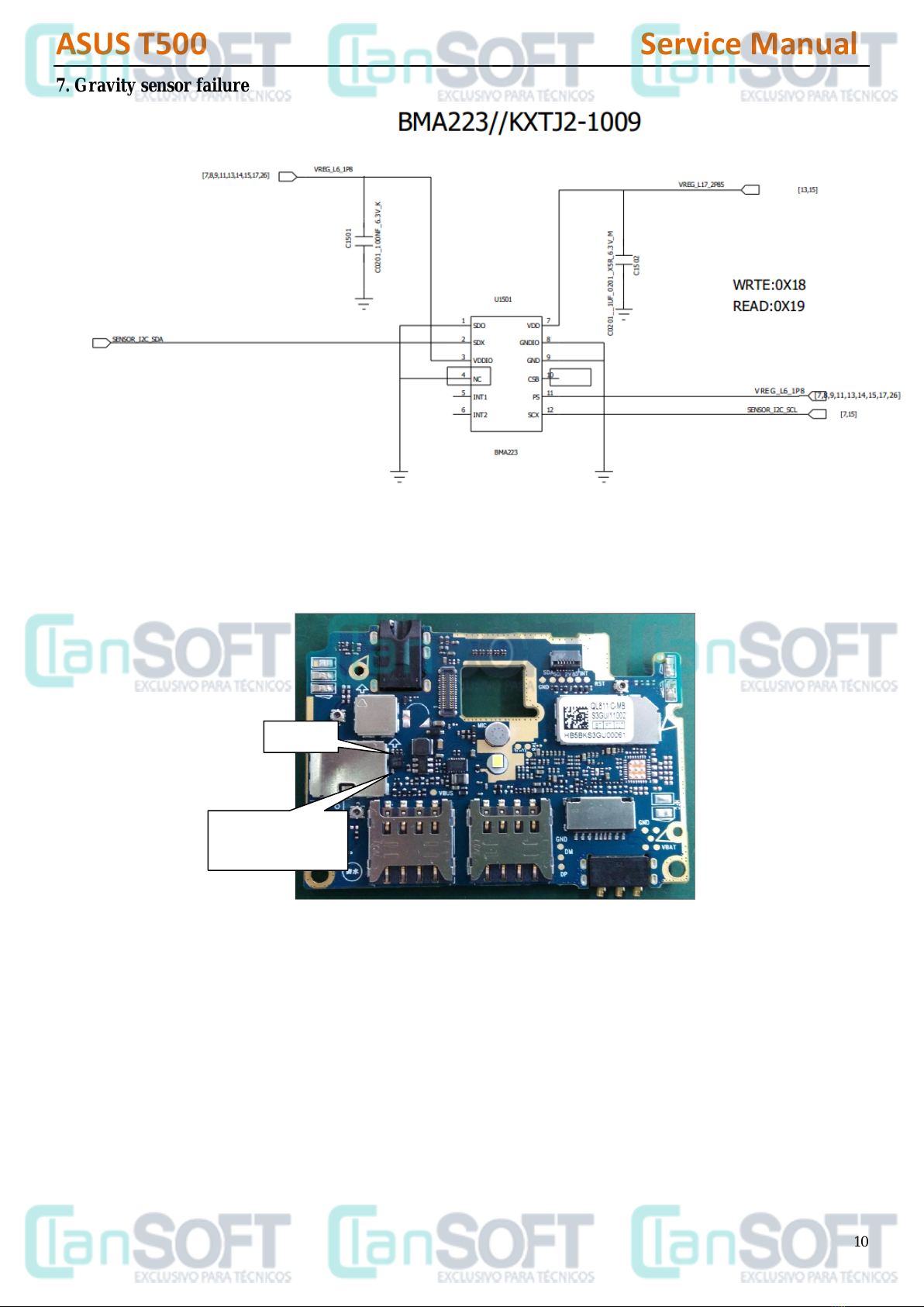
7. Gravity sensor failure...........................................................................................................................................10
8. Side key FPC failure............................................................................................................................................11
9. Cannot get charged, fail to identify USB.............................................................................................................12
10. Rear camera function failure.............................................................................................................................13
11. Front camera function failure.............................................................................................................................14
12.Flash failure........................................................................................................................................................15
13. GSM network failure..........................................................................................................................................16
14. CDMA network failure........................................................................................................................................18
15. LTE network failure............................................................................................................................................20
16. WIFI/ BT failure..................................................................................................................................................22
17. GPS failure ........................................................................................................................................................23
18. FM failure...........................................................................................................................................................25
19. Fail to identify earphone/Handset MIC failure...................................................................................................26
20. MIC no sound/small sound................................................................................................................................27
21. Receiver no sound.............................................................................................................................................28
22. Speaker no sound .............................................................................................................................................29
23. Fail to identify SIM card.....................................................................................................................................29
24. Fail to identify T-flash card ................................................................................................................................31