AT&T FIRSTNET AirgainConnect AC-HPUE User manual

AirgainConnect™ AC-HPUE User Guide
AirgainConnect®AC-HPUE and
Ethernet Injector User Guide
2/25/2021
Version 1.10

Blank Page

AirgainConnect® AC-HPUE User Guide
© Copyright 2020 Airgain, Inc. i
This document is the User Guide for the AirgainConnect®AC-HPUE products marketed and
sold by Airgain, Inc. It is provided to aid in installing and operating the AirgainConnect
integrated vehicle modem and antenna. This guide and the subject matter it contains are
protected by copyright laws under the Copyright Act of 1976, as amended, and all copyrights in
this guide are the exclusive property of Airgain, Inc. The user of the applicable AC-HPUE shall
be able to make a limited number of copies of this guide for the sole purpose of properly
installing and operating the product, but only such copies as are reasonably necessary for that
purpose. If any other copies or distribution of this guide or any of its contents are desired, please
contact Airgain, as such rights are only available through written permission. AirgainConnect
and Airgain are trademarks or registered trademarks of Airgain, Inc. The AC-HPUE is powered
by Assured Wireless HPUE.
Revision History
Version
Date
Comment
1.0
4/17/2020
First Version
1.1
6/24/2020
Revised: SIM door/tray and SIM installation; LED status table;
removed plastic thermal bushing; added 3rd optional Wi-Fi; updated
DC voltage and power; updated temperature range; added AT
commands to reset the mode of the antenna-modem when connecting
it to a laptop.
1.2
9/4/2020
Added note that antenna-modem must be powered by the ethernet
injector, not by direct connect to vehicle.
1.3
9/13/2020
Added ethernet injector detail
1.4
10/2/2020
Added FirstNet Ready logo
1.5
10/22/2020
Changed torque on SIM door to 4 inch-pounds
1.5
10/29/2020
Added EI to document title and added image of EI label
1.6
11/17/2020
Changed inline fuse to 5A slow blow
1.6
11/17/2020
Added FCC certification information
1.7
1/27/2021
Added footnote explaining optional cable lengths available
1.8
2/11/2021
Added note about router WAN configuration for DHCP
1.9
2/17/2021
Removed Section 7 on direct connect to laptop
1.10
2/25/2021
Added warning to use a proper DC power supply
Safety Warnings
•SEVERE DAMAGE WARNING. The AC-HPUE must be powered by the Ethernet Injector (AC-EI)
or an ISO 7637-2 compliant power conditioner when connected to a DC power source. Direct
connection to the vehicle’s battery or electrical system is prohibited and can significantly
damage the AC-HPUE –damage resulting from improper power supply is NOT covered by the
warranty.
•HOT. Do not touch the antenna-modem while operating. Power it off and allow it to cool
down for 30 minutes to a safe temperature after use before touching it.
•MAINTAIN A SAFE DISTANCE. Stay 20 cm (8 inches) or more away from the antenna modem
during normal operation.
•FUSE. Use an inline 5A slow blow fuse for over-current protection.
•GROUND. Never connect the black ground wire directly to the battery terminal.

AirgainConnect® AC-HPUE User Guide
© Copyright 2020 Airgain, Inc. ii

AirgainConnect® AC-HPUE User Guide
© Copyright 2020 Airgain, Inc. iii
Table of Contents
1. Welcome..................................................................................................................................................1
2. Package Contents......................................................................................................................................2
3. Key Features.............................................................................................................................................2
4. Antenna-Modem Installation .....................................................................................................................3
5. Ethernet Injector.......................................................................................................................................8
6. Vehicle Router Configuration ...................................................................................................................12
Appendix A: Specifications...............................................................................................................................15
Appendix B: Safety Warnings ...........................................................................................................................17
Appendix C: Limited Warranty, Support ............................................................................................................18
Appendix D: Compliance..................................................................................................................................21
Appendix E: Terms of Use and Privacy .............................................................................................................. 23
Applicable Terms ............................................................................................................................................23

AirgainConnect® AC-HPUE User Guide
© Copyright 2020 Airgain, Inc. iv
Trademark, and Patent....................................................................................................................................23

AirgainConnect® AC-HPUE User Guide
© Airgain, Inc. 2020. All Rights Reserved. 1
1. Welcome
This user guide provides information on the AirgainConnect AC-HPUE integrated vehicle
antenna and LTE modem. AirgainConnect AC-HPUE is built for FirstNet® MegaRange™, the
high power user equipment (HPUE) solution that transmits at a higher power when connected on
Band 14. This results in increased coverage and performance. AC-HPUE optionally includes two
Wi-Fi antennas, a GNSS low noise amplified antenna, and the associated coax cables to connect
these antennas directly to the vehicle router. Public safety agencies can obtain a FirstNet SIM
(Subscriber Identification Module) by opening a FirstNet account at any AT&T sales location or
distribution partner. If you have a FirstNet SIM, you will default to band 14 and the higher
power of the HPUE.
While the AC-HPUE is ideal for public safety vehicles, it also brings performance benefits to
enterprise vehicles because it supports all AT&T bands and provides superior performance on
those bands when compared to a conventional vehicle router modem and antenna. In addition to
vehicle applications, the AC-HPUE can also be used in stationary applications like a dispatch
center.
Diagram 1: Active Antenna-Modem with Passive Wi-Fi and GPS

AirgainConnect® AC-HPUE User Guide
© Airgain, Inc. 2020. All Rights Reserved. 2
2. Package Contents
Description
Quantity
Insert sheet
1
Antenna-modem with cables*
1
Mounting nut
1
Plastic washer
1
FirstNet SIM (factory installed in the antenna-modem)
1
Alcohol wipe
1
Ethernet injector (except when SKU without this part is purchased)
1
-Ethernet Injector mounting screws
2
-Power cable
1
-Ethernet cable
1
* NOTE: The antenna-modem cables are available in 5-, 7-, and 10-meter lengths (16.4-, 22.9-, and
32.8-foot lengths). Approximately 10cm (4 inches) of cable are not useable because it is on the inside
of the device.
3. Key Features
•HPUE power class 1 on band 14
•Support of all AT&T bands
•Modem directly attached to antenna, resulting in full transmit power to antenna elements
•Rugged outdoor enclosure
•Power conditioning to protect against voltage spikes in automotive applications
•USB to Ethernet interworking –connects to router WAN port
•LED indicator to easily determine status
•Transparent support of VPNs
•IP passthrough
•Complies with environmental standards
•Sleeps and draws less than 4ma when ignition sense is off AND router sleep sense is off.
Awake whenever either ignition sense is on OR sleep sense is on.

AirgainConnect® AC-HPUE User Guide
© Airgain, Inc. 2020. All Rights Reserved. 3
4. Antenna-Modem Installation
1. The antenna must be installed to maintain a minimum 7.87 in (20 cm) distance between the
antenna and nearest person during normal use.
2. The antenna must be mounted at least 18 in (45.72 cm) away from any other communication
antenna to maintain specified performance and limit interference to other in-vehicle
communication systems.
3. Only the antennas bundled in the device with the RF module may be used. No other antennas
are approved.
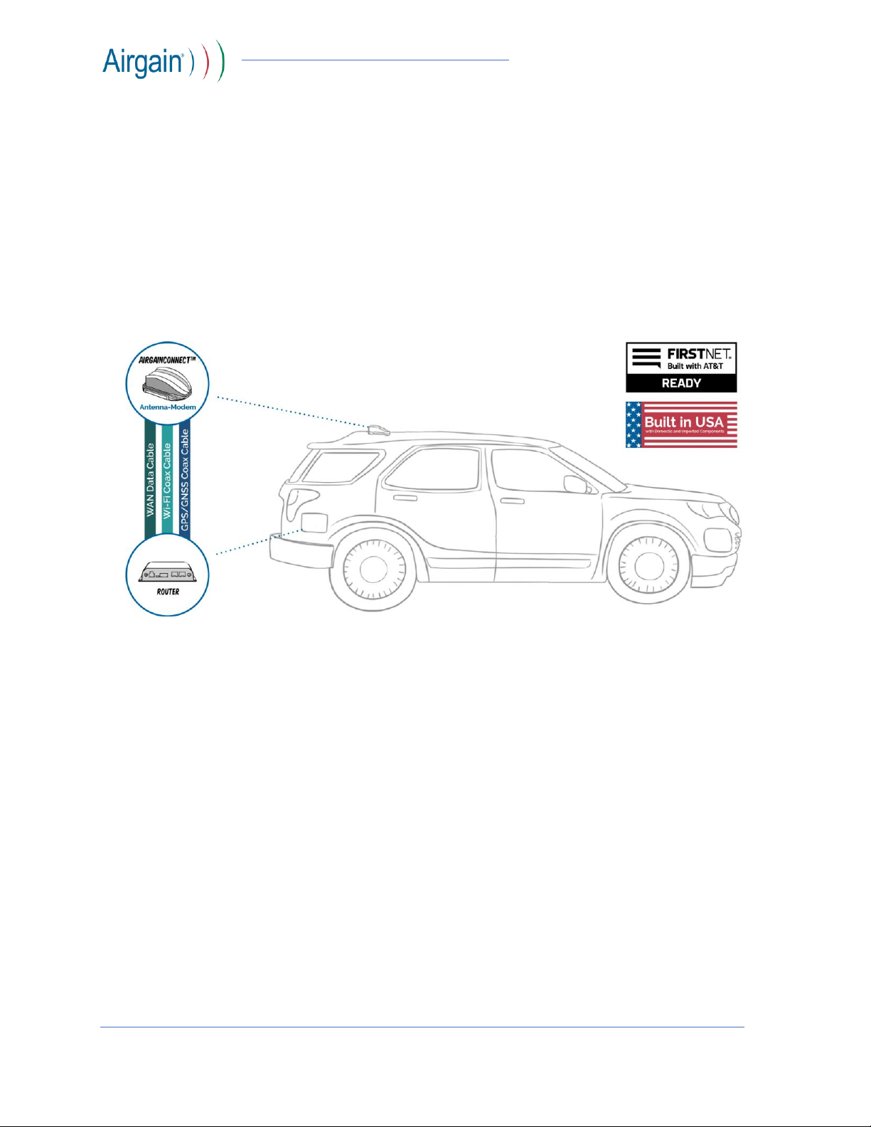
4. The antenna-modem must be powered by the Airgain-supplied ethernet injector or power
supply to protect it from voltage spikes that may occur in vehicle power systems.
In the event that these conditions cannot be met (for example certain laptop configurations or co-
location with another transmitter), then the FCC authorization is no longer considered valid and
the FCC ID cannot be used on the final product. In these circumstances, the OEM integrator will
be responsible for re-evaluating the end product (including the transmitter) and obtaining a
separate FCC authorization.
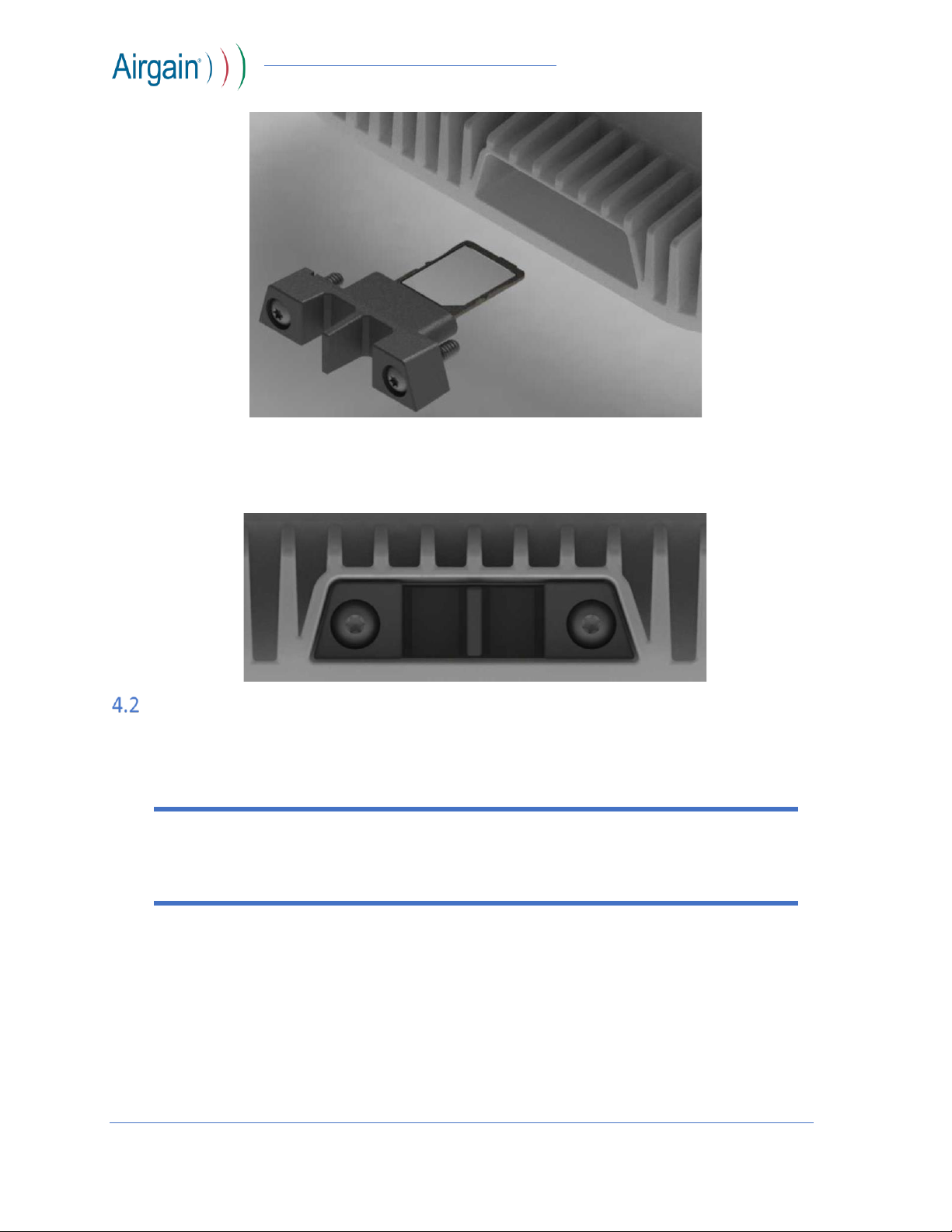
SIM Installation
The antenna-modem is shipped from the factory with a FirstNet SIM installed. The ICCID of
the SIM is on the label attached to USB cable of the antenna-modem. There is no need to
remove the SIM tray –simply add the ICCID of the SIM to your FirstNet account. If the SIM
must be removed and replaced, please follow the procedure below.
1. Disconnect power from the modem housing.
2. Remove the SIM door retaining screws using a Torx size T10 wrench. The screws are self-
retained in the SIM door to prevent accidental loss.
3. Pull the door out using needle-nose pliers.
4. Remove the SIM tray from the modem.
Important! Directly connecting the antenna-modem to the vehicle power may
result in damage to the antenna-modem.

AirgainConnect® AC-HPUE User Guide
© Airgain, Inc. 2020. All Rights Reserved. 4
5. Install the 3FF micro SIM in the SIM tray.
6. Install the SIM tray in the modem.
7. Secure the SIM door with the screws. DO NOT OVER-TWIST –torque to 4 inch-lbs.
Antenna-Modem Housing Installation
1. Choose a location on vehicle roof.
Select a location on the vehicle roof that has a flat area large enough for the base of
the AirgainConnect housing.
Note: Ford Interceptor Utility model 2020 and later may require mounting on top of a
roof rib due to the tight spacing between ribs. Contact your distributor or Airgain for the
appropriate base gasket if needed.
Important! Prior to mounting, the mounting surface must be heated to a temperature
of between 85 to 100F (30C to 38C). Use a heat gun and a laser temperature reading
gun to make ensure the surface is heated properly.
1

AirgainConnect® AC-HPUE User Guide
© Airgain, Inc. 2020. All Rights Reserved. 5
2. Drill a 1 in (2.54 cm) diameter hole where the center of the antenna-modem housing will be
located on the vehicle. Verify the hole will not interfere with headliner mounted accessories,
such as dome lighting.
3. Clean the mounting surface with the provided alcohol wipe to remove dust, dirt and oil. Allow
surface to dry.

AirgainConnect® AC-HPUE User Guide
© Airgain, Inc. 2020. All Rights Reserved. 6
4. Insert the cables through the hole.
5. Removing the backing on the bottom of the housing exposing the adhesive pad.
6. Position the housing and adhere it to the vehicle using firm hand pressure.
2

AirgainConnect® AC-HPUE User Guide
© Airgain, Inc. 2020. All Rights Reserved. 7
7. Place the plastic thermal washer on the threaded lug and then install the nut on the threaded
lug. Tighten the nut two turns after contact to inside surface. Attach the Wi-Fi and GNSS
cables to the vehicle router Wi-Fi and GPS ports.
Notes:
•The Installer may encounter various obstacles with individual vehicle designs that may require
different placement, routing of cables or drilling of holes to complete the mounting
procedure.
•Mount the housing on the outside of the vehicle (roof or trunk).
•The housing must be mounted horizontally, parallel to the ground (not mounted on a vertical
surface).
•The housing must be mounted to a flat, clean dry surface. Avoid mounting the housing near
panel seams or rivets so the foam pad can seal properly.
•The housing should be installed with a minimum distance of 18 inches from existing antennas,
light bars or obstacles protruding from the roof or trunk lid of the vehicle.
•The antenna must be mounted at least 18 inches away from any other communication
antenna to maintain specified performance and limit interference to other in-vehicle
communication systems.
•When routing cables, pull on the body of the cable only!
•When routing cables, DO NOT PULL ON CONNECTORS! Pulling directly on connectors may
cause damage and loss of the signal at the radio receiver, GPS or modem.
•When mounting, make sure that the surface temperature where the housing is to be
mounted is between 85°F to 100°F (30°C to 38°C)! Cooler surface temperatures will cause
improper adhesion to the surface.

AirgainConnect® AC-HPUE User Guide
© Airgain, Inc. 2020. All Rights Reserved. 8
5. Ethernet Injector
•The ethernet injector’s primary purpose is to perform Ethernet-to-USB-C interworking.
Additionally, it provides power conditioning to protect the antenna modem from voltage
spikes. The AC-HPUE must be powered by the Ethernet Injector (AC-EI) or an ISO 7637-2
compliant power conditioner when connected to a DC power source. Direct connection to
the vehicle’s battery or electrical system is prohibited and can significantly damage the AC-
HPUE –damage resulting from improper power supply is NOT covered by the warranty.
View
Item
Description
Rear
Power In
Connects to vehicle power, ground, ignition sense, and
router USB sleep sense
Rear
Ethernet LAN connector
Connects to the router WAN port
Front
Power out
Connects power to the modem housing
Front
Modem
Connects LTE data over USB to the modem
Front
Status indicator
Displays operational status
Front
Reset switch
Press to reset the ethernet injector
Table 1: Ethernet Injector Interface Descriptions
Diagram 2: Ethernet Injector Connection to Router Ethernet WAN Port

AirgainConnect® AC-HPUE User Guide
© Airgain, Inc. 2020. All Rights Reserved. 9
Status Indicator
The multi-color LED on the ethernet injector indicates operational status.
State
Indicator Color
Description
Power off
& sleeping
Off
The LED is off when the power is off or the device is sleeping
Booting up
Blue
Solid blue while booting up
No SIM card
Red
Solid red after bootup when there is no valid SIM card
No signal
Red/Green/Blue
Blinking red after bootup when there is no cellular coverage signal,
followed by blinking green, followed by reboot solid blue
No USB
connection
Red
Blinking red after bootup when there is no connection to the
antenna-modem
Connecting
Green blink
Blinking green while connecting to the cellular network.
Connected
Green
Solid green when connected to the cellular network
Table 2: Status Indicator
Ethernet Injector Label
The part number, serial number and MAC address are shown on the label on the bottom of the
Ethernet Injector.
Diagram 3: Ethernet Injector Connection to Laptop Docking Station Ethernet Port

AirgainConnect® AC-HPUE User Guide
© Airgain, Inc. 2020. All Rights Reserved. 10
Installation
1. Mount the ethernet injector near the vehicle router using the included screws. Orient it with
the LED facing in a direction that enables it to be easily viewed.
2. Connect USB data cable and 2-pin power cable from the roof-top antenna-modem housing to
the ethernet injector.
3. Connect the ethernet injector 4-pin power cable to the vehicle power and ignition before
connecting the cable to the ethernet injector. Make sure that the cables have slack, are
tucked away, and secured so they are not accidently pulled out when placing and removing
items in the vehicle trunk.
Connect the following:
oRed wire to +12VDC that is always-on, even when the ignition is off.
oBlack wire to ground (not directly to the vehicle battery)
Important! Use an inline 5A slow blow fuse for over-current protection.

AirgainConnect® AC-HPUE User Guide
© Airgain, Inc. 2020. All Rights Reserved. 11
Diagram 4: Ethernet Injector Cable Pinout and Wire Color
oOrange wire to the vehicle ignition or accessory circuit. For applications where the
device is always on (non-vehicular applications), connect the orange ignition sense wire
to the red +12VDC wire.
4. Optional: Connect the USB sleep sense connector to the vehicle router USB port. For the
MG90 model router (second image below), be sure to connect to USB 1 because only this USB
port cycles power on when the router awakens.
oThis step is optional and enables the ethernet injector to detect when the router is
sleeping.
oIt is only required if delayed shutdown is used in the router configuration and you
would like the antenna-modem and ethernet injector to sleep at the same time the
router sleeps.
Diagram 5: Connections to Cradlepoint IBR900 Router
Important! Never connect the black ground wire directly to the battery terminal.

AirgainConnect® AC-HPUE User Guide
© Airgain, Inc. 2020. All Rights Reserved. 12
Diagram 6: Connections to Sierra Wireless MG90 Vehicle Routers
5. Connect the Ethernet cable from the ethernet injector to the vehicle router WAN port.
6. Connect the Wi-Fi and GNSS coax cables to the vehicle router Wi-Fi and GPS ports.
Ethernet Injector Reset
Press the Reset button on the front of the ethernet injector for one second to reset the ethernet
injector.
6. Vehicle Router Configuration
AC-HPUE provides high performance LTE coverage compared to a conventional modem in the
vehicle router and therefore should be the primary LTE connection. Below are two examples of
how to set the router WAN port as the primary LTE connection.
Cradlepoint IBR900
1. Select the Connection Manager tab
2. Click on the Ethernet-WAN up/down arrow icon.
3. Drag and drop the icon to the top to make Ethernet-WAN the primary mobile network
connection.
4. Click on the internal modem up/down arrow icon.
5. Drag and drop the internal modem icon to just below the Ethernet-WAN to make it the
backup mobile network connection.

AirgainConnect® AC-HPUE User Guide
© Airgain, Inc. 2020. All Rights Reserved. 13
Check the WAN port setting and confirm it is set to DHCP. The router will get an IP address
from the Ethernet Injector via DHCP. The IP address from the mobile network will be passed
through to the router.
Sierra Wireless MG90
To configure the WAN port (Ethernet 5) a higher priority than the internal modem, do the
following steps:
1.
2.
3.
To configure the internal modem lower priority, do the following:
1.
2.

AirgainConnect® AC-HPUE User Guide
© Airgain, Inc. 2020. All Rights Reserved. 14
3.
Check the status of the two links. In this example, the WAN port and the internal modem are
both up. However, the traffic goes over the WAN port only and this is shown by it being
placed it at the top of the status list and highlighting it.
Table of contents
Other AT&T Modem manuals

AT&T
AT&T DataPort PCX Modem User manual

AT&T
AT&T Paradyne COMSPHERE 3900 Series User manual

AT&T
AT&T Turbo Hotspot 2 User manual

AT&T
AT&T USB800 Installation instructions

AT&T
AT&T 3G MicroCell User manual

AT&T
AT&T High Speed Internet Service User manual

AT&T
AT&T USBConnect Mercury User manual

AT&T
AT&T IIM2100M User manual

AT&T
AT&T AT&T USBConnect Force 4G User manual

AT&T
AT&T U120 User manual
Popular Modem manuals by other brands

Patton electronics
Patton electronics 1080A user manual

US Robotics
US Robotics 000698-13 - New features

Motorola
Motorola SURFboard SB5102 Specification sheet

Telenetics
Telenetics Flash Poll DSP 9612 user guide

Comtrend Corporation
Comtrend Corporation NL-3120 Installation & setup

Orcon
Orcon GENIUS How to install