Atari 400 User manual

ATARI
400/800
Service Manual

CHAPTER 1 - GENERAL INFORMATION 1-1
1.1 Introduction 1-1
1.2 ATARI 400/800 Computer Console Description 1-1
1.3 How to use this Manual 1-2
1.3.1 General Information 1-3
1.3.2 Installation 1-3
1.3.3 System Operation 1-3
1.3.4 Functional Description 1-3
1.3.5 Maintenance 1-3
1.3.6 Spare Parts List and
Ordering/Reporting information 1-4
1.4 Changes to this Manual 1-4
1.4.1 Notice of Changes Page 1-4
1.4.2 List of Effective Pages 1-4
1.4.3 Reader Comment Form 1-4
1.5 Safety 1-5
1.6 Related documentation 1-6
1.7 ATARI 400/800 Computer Consoles
Physical Description 1-7
1.8 Optional Equipment 1-10
1.9 Specifications 1-11
CHAPTER 2 - ATARI 400/800 COMPUTER INSTALLATION 2-1
2.1 Introduction 2-1
2.2 Unpacking 2-1
2.3 Connecting the TV Switch Box 2-2
2.4 Connecting the Program Cassette Recorder 2-3
2.5 Connecting the AC Power Adapter 2-4
2.6 Inserting Program Cartridge 2-4
2.7 Connecting Television Monitor 2-4
2.8 Connecting the ATARI 810 and 815 Disk Drive 2-7
2.9 Connecting the ATARI 820 and 822 Printer 2-7
2.10 Using the ATARI 850 Interface Module 2-8
2.10.1 Connecting the ATARI 850 Interface Module 2-8
2.10.2 Connecting the ATARI 825 Printer 2-9
2.10.3 Connecting the ATARI 830 Acoustic Modem 2-10
CHAPTER 3 - SYSTEM OPERATION 3-1
3.1 Introduction 3-1
3.2 System Power-Up 3-1
3.2.1 System Power-Up without Disk Drive 3-1
3.2.2 System Power-Up with Disk Drive 3-2
3.3 Keyboard and Screen Editor Functions 3-2
3.4 Program Cartridge System Keys 3-7
3.5 Operation of Hand Controllers 3-7
3.6 ATARI 410 Program Cassette Recorder 3-7
3.6.1 Operation of the Program Recorder 3-7
3.6.2 Transfer a Program to Cassette Tape 3-8
3.6.3 Transfer a Program from Tape to Computer 3-9
CHAPTER 4 - FUNCTIONAL DESCRIPTION 4-1
4.1 Introduction 4-1

4.2 The ATARI 400 and 800 Computer Console Systems 4-1
4.2.1 Motherboard 4-1
4.2.2 Central Processing Unit 4-2
4.2.3 ROM Personality Board 4-3
4.2.4 RAM Memory pcb 4-3
4.2.5 Keyboard 4-4
4.2.6 Power Supply 4-4
4.2.7 Program Cartridge 4-4
4.3 Functional Block Diagram Discussion 4-4
4.3.1 Central Processing Unit 4-5
4.3.2 Motherboard Console System {400) 4-7
4.3.2.1 POKEY Integrated Circuit 4-8
4.3.2.2 Peripheral Interface Adapter (PIA) 4-9
4.3.2.3 KeyIn/KeyOut Integrated Circuits 4-12
4.3.2.4 Memory Map Decoder 4-12
4.3.2.5 I/O Decoder 4-13
4.3.3 Motherboard Console System (800) 4-14
4.3.3.1 Bidirectional Data Buffer 4-14
4.3.3.2 I/O Decoder 4-14
4.3.3.3 Composite Video 4-14
4.3.4 ROM Personality Board 4-14
4.3.5 RAM Memory Boards 4-16
4.3.6 Power Supply 4-16
4.3.7 Program Cartridge 4-17
CHAPTER 5 - MAINTENANCE 5-1
5.1 Introduction 5-1
5.2 Preventive Maintenance 5-1
5.2.1 PCB Contact Cleaning and Lubrication 5-2
5.2.2 Visually Inspecting the Computer Consoles 5-3
5.3 System Check-Out 5-3
5.3.1 Memo Pad Test 5-3
5.3.2 Shock Test 5-5
5.3.3 Picture Quality Test 5-5
5.3.4 Keyboard Test 5-6
5.3.5 Stand Alone Test (Diagnostic) 5-7
5.4 Troubleshooting Guide 5-18
5.4.1 Troubleshooting -- Procedure Number One 5-19
5.4.2 Troubleshooting -- Procedure Number Two 5-21
5.4.3 Troubleshooting -- Procedure Number Three 5-23
5.4.4 Integrated Circuit Replacement Procedures 5-23
5.4.5 Motherboard 5-27
5.5 Dissassembly, 400Computer Console 5-30
5.6 Disassembly, 800 Computer Console 5-33
5.7 Assembly, 400 Computer Console 5-40
5.8 Assembly, 800 Computer Console 5-43
CHAPTER 6 - SPARE PARTS LIST AND ORDERING/REPORTING INFORMATION 6-1
6.1 Introduction 6-1
6.2 Spare Parts List 6-1

FIGURES
Figure 1-1. The ATARI 400/800 Computer Consoles 1-2
Figure 1-2. Sample Notice of Changes Page 1-5
Figure 1-3. ATARI 400/800 Computer Console Systems 1-8
Figure 1-4. ATARI 400 Computer Console, Side View 1-9
Figure 1-5. ATARI 800 Computer Console, Side View 1-10
Figure 2-1. Conversion to 300 Ohm Antenna Input Impedance 2-3
Figure 2-2. ATARI 400/800 Computer Consoles, Side View 2-5
Figure 2-3. 400/800 Consoles, Cartridge Door Open 2-6
Figure 2-4. ATARI Disk Drive Cable Connections 2-8
Figure 2-5. ATARI 40 Column Printer Cable Connections 2-9
Figure 2-6. ATARI 850 Interface Module Cable Diagram 2-10
Figure 3-1. The ATARI Keyboard 3-3
Figure 3-2. Special Graphics Using the CTRL Key 3-4
Figure 3-3. Special Graphics Using the ESC Key 3-5
Figure 3-4. SHIFT Keyboard and Key Combination 3-6
Figure 4-1. Major Functional Modules of the ATARI 400/800 4-18
Figure 4-2. Block Diagram of the CPU Board 4-19
Figure 4-3. Schematic Diagram of the CPU Board 4-20
Figure 4-4. Atari 400 motherboard Block Diagram 4-21
Figure 4-5a. Atari 400 motherboard schematic part 1 4-22
Figure 4-5b. Atari 400 motherboard schematic part 2 4-23
Figure 4-6. Pin Assignments of ATARI Custom Chips POKEY,
ANTIC and CTIA 4-24
Figure 4-7. Block Diagram of the Motherboard Console System (800) 4-27
Figure 4-8a. Schematic Diagram of Motherboard Console System(800) 4-28
Figure 4-8b. Schematic Diagram of Motherboard Console System(800) 4-29
Figure 4-9. Block Diagram of the ROM Personality Board 4-30
Figure 4-10. Schematic Diagram of the ROM Personality Board 4-31
Figure 4-11. Block Diagram of the RAM Board (8K) 4-32
Figure 4-12. Schematic Diagram of the RAM Board (8K) 4-33
Figure 4-13. Block Diagram of the RAM Board (16K) 4-34
Figure 4-14. Schematic Diagram of the RAM Board (16K) 4-35
Figure 4-15. Block Diagram of the Power Supply (400) 4-36
Figure 4-16. Schematic Diagram of the Power Supply (400) 4-37
Figure 4-17. Block Diagram of the Power Supply (800) 4-38
Figure 4-18. Schematic Diagram of the Power Supply (800) 4-39
Figure 4-19. Block Diagram of a Program Cartridge 4-40
Figure 4-20. Schematic Diagram of a Program Cartridge 4-41
Figure 5-1. System Check-Out Flowchart 5-4
Figure 5-2. Stand Alone Test Special Tools 5-8
Figure 5-3. Any Video Test Screen Display 5-10
Figure 5-4. Graybar Test Screen Display 5-11
Figure 5-5. Color Bar Test Screen Display 5-12
Figure 5-6.400 Console Color Adjustment 5-13
Figure 5-7. 800 Console Color Adjustment 5-14
Figure 5-8. RAM Test Matrix Screen Display 5-15
Figure 5-9. PORT Test Error Table Screen Display 5-17
Figure 5-10. 400 Console, Assembled Without Casting 5-20
Figure 5-11. 800 Console, Assembled Without Casting 5-21
Figure 5-12. RAM Memory Board Locations, 8K 5-24
Figure 5-13. RAM Memory Board Locations, 16K 5-25
Figure 5-14. CPU Printed Circuit Board, Locations 5-26
Figure 5-15. 400 Console Motherboard, Locations 5-28
Figure 5-16. 800 Console Motherboard, Locations 5-29
Figure 5-17. 400 Console, Bottom Cover Screw Location 5-31
Figure 5-18. 400 Console, Top Cover Removal 5-32
Figure 5-19. 400 Console, Keyboard Removal 5-32
Figure 5-20. 400 Console, Power Supply Removal 5-35
Figure 5-21. 400 Console, Module Assembly 5-36
Figure 5-22. 800 Console, Cartridge Door Assembly Removal 5-37
Figure 5-23. 800 Console, Bottom Cover Removal 5-38
Figure 5-24. 800 Console, Keyboard Removal 5-39
Figure 5-25. 800 Console, Module Assembly Removal 5-40
Figure 5-26. 800 Console, Power Supply Removal 5-41
Figure 5-27. 800 Console, CPU Printed Circuit Board Removal 5-41
Figure 5-28. 800 Console, Motherboard Removal 5-42
TABLES
Table 1-1. ATARI 400 Computer Console Specifications 1-11
Table 1-2. ATARI 800 Computer Console Specifications 1-12
Table 4-1 PIA Register Selection and Function 4-10
Table 4-2 Memory Map Select Lines 4-12
Table 4-3 I/O Decoder Select Lines 4-13
Table 5-1. Troubleshooting Guide 5-18

CHAPTER 1 - GENERAL INFORMATION
1.1 INTRODUCTION
This 400/800 System Service Manual is a reference guide for the serv-
ice technician. The information presented in this manual, when used
in conjunction with ATARI training, will enable a service technician
to install, operate, and maintain the ATARI 400/800 Computer Systems.
In addition to basic user operating instructions, this manual
includes procedures that describe operating the ATARI 400/800
Computer Console in conjunction with peripheral equipment for
maintenance purposes.
This manual further describes the functional operation of the 400/800
ATARI Computer Consoles and provides detailed procedures for its
maintenance. This information will enable a service technician to
troubleshoot and repair the ATARI 400/800 Computer Consoles to the
replaceable integrated circuit level. None of the procedures included
require special test equipment or tools. This manual also provides
spare parts ordering information to replace expended units and/or
assemblies, and the fault reporting procedures required.
1.2 ATARI 400/800 COMPUTER CONSOLE DESCRIPTION
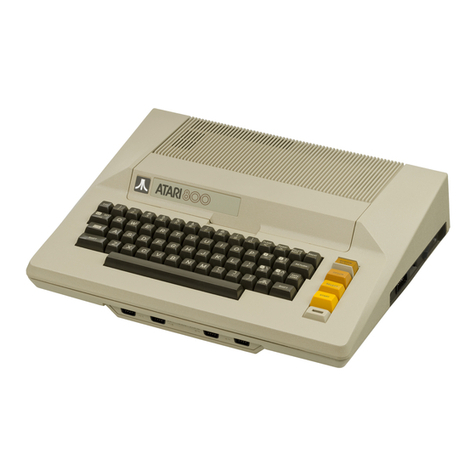
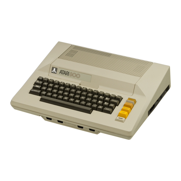
The ATARI 400/800 Computer Consoles, see Figure 1-1, are personal
microcomputers designed to provide entertainment, in the form of
games; education, using interactive, audio-visual, education
programs; information, providing a serious tool for home and business
information management; plus perform all the functions of a fully
programmable general purpose computer.
The ATARI 400 Computer Console contains the central processor unit
(CPU) and memory in the form of the Operating System read-only-memory
( ROM ) and 8K (8 x 1 024 bytes) of user programmable random access
memory (RAM), expandable to 16K (16 x 1024 bytes). The Console also
holds the keyboard, cartridge slot, controller jacks, and a serial
I/O port for connecting to peripheral devices.
The ATARI 800 Computer Console contains the central processor unit
(CPU) a nd memory in the form of the Operating System read-only-
memory (10K ROM) and 8K-16K (standard) of user programmable random-
accessmemory (RAM), and two Expansion Sockets for additional RAM
modules (maximun 48K). The Console also holds the keyboard, cartridge
slots, controller jacks and a serial I/O port for connecting to
peripheral devices.
Atari Personal Computers 1-1

Figure 1-1. The ATARI 400/800 Computer Consoles
1.3 HOW TO USE THIS MANUAL
This manual is organized into six chapters:
Chapter 1 General Information
Chapter 2 Installation
Chapter 3 System Operation
Chapter 4 Functional Description
Chapter 5 Maintenance
Chapter 6 Spare Parts List and Ordering/Reporting Information
Each chapter contains only the information needed to fulfill its
function. If a given subject applies to more than one chapter, then
the subject will be discussed in the chapter where it is most used;
other chapters would then refer to the chapter and paragraph
containing the subject.
First- and second-level paragraphs in the manual contain unique 2-
and 3-digit numbers, respectively, in the paragraph heading. The
first digit is always the same as the number of the chapter. Third-
and forth-level paragraphs contain lower case letters and numbers in
parentheses, respectively, in the paragraph heading. Paragraghs are
referenced in text by their number (e.g., 5.4.2 a nd 5.4.9c).
Figures and tables are numbered sequentially on a chapter basis. The
first digit of a figure or table number is always the numbe r of the
chapter. Tables appear one time, following their first reference in
text.
1-2 System Service Manual

Figures also appear one time after their first reference in text,
unless repeating the figure is easier than having the reader refer
back.
1.3.1 General Information
This chapter contains a general description of the ATARI 400/800 Com-
puter Consoles, a physical description of the system (dimensions,
weights, and operating specifications), and a summary of the periph-
eral equipment used with the system. All system operating features
and options are described.
This chapter also contains general information such as the scope of
the manual and how to use the information in it. Also, it provides
safety precautions unique to the ATARI 400/800 Computer Systems and a
listing of related documents.
1.3.2 Installation
Chapter 2 contains detailed procedures for unpacking, system setup
and initialization, checkout and repacking.
1.3.3 System Operation
Chapter 3 contains procedures for system power-up, using the keyboard
and screen editor functions, using program cartridge system keys, and
controllers and operating the program cassette recorder.
1.3.4 Functional Description
Chapter 4 provides a functional description of the ATARI 400/800 Com-
puter Console systems. The functional description will be presented
using a functional block diagram discussion to the integrated circuit
level. This information is presented to familiarize the service tech-
nician with the ATARI 400/800 Computer Console as a system, thereby
providing him/her with a basis for troubleshooting system faults.
1.3.5 Maintenance
Chapter 5 presents preventive maintenance, troubleshooting, and
repair instructions. Preventive maintenance includes instructions for
normal cleaning and inspection tasks. The troubleshooting portion of
the chapter presents symptom probable-cause corrective action types
of tables. The repair portion of the chapter provides instructions
for replacing printed circuit assemblies, whole assemblies, and
specific integrated circuits in keeping with the ATARI maintenance
philosophy.
ATARI Personal Computers 1-3
1.3.6 Spare Parts List and Ordering/Reporting Information

Chapter 6 provides ATARI part numbers for the field replaceable units
of the 400/800 Computer Console system. The chapter also provides
information for ordering the parts through the nearest ATARI parts
distribution center. In addition chapter 6 provides information on
how to use the Fault Reporting System.
1.4 CHANGES TO THIS MANUAL
This manual will periodically be updated or changed to keep it
current with changes in the ATARI 400/800 Computer Console systems.
Changes normally start with ATARI Customer Support issuing a "Tech
Tips" that alerts the service technician to such things as changes in
maintenance procedures and critical problem areas. After either a
series of these Tech Tips are issued or one of an extremely critical
nature is issued, service manual change pages are published. These
pages are of the remove-the-old-and-insert-the-new type. A vertical
bar in the margin of the changed page indicates the revised material.
After about 20% of a manuals pages are changed, Customer Support
Publications reissues the entire manual.
1.4.1 Notice of Changes Page
The Notice of Changes page, see Figure 1-2, contains instructions for
changing this manual. It will come with pages intended to replace
outdated pages in the manual. The Notice contains the affected page
number and the action required to make the changes. After making the
necessary changes, insert the Notice at the end of the manual to keep
a current record of changes.
1.4.2 List of Effective Pages
The List of Effective Pages on the back of this manual's title page
lists all the pages in this book, including the title page, the List
of Effective Pages, deleted pages, added pages, and foldout pages.
1.4.3 Reader Comment Form
ATARI Customer Support Publications Department created the Reader
Comment Form (at the back of this manual) to get feedback from the
service technician about our manuals. If you are in any way
dissatified with this publication, we want to hear from you. Tell us
about technically inaccurate information, gross typographical errors,
or missing information. If you know a way to improve a procedure,
please let us know that, too. When filling out the form, be specific
and give the page number and a line reference with paragraph number,
if possible.
1-4 System Service Manual

Figure 1-2. Sample Notice of Changes Page
ATARI Personal Computers 1-5

1.5 SAFETY
As with any electronic equipment, precautions consistent with all
standard industrial safety practices must be observed while maintain-
ing the ATARI 400/800 Computer Console systems. A current of 10 mA
can put the human heart in fibrillation and a current of only 100 mA
can cause it to stop completely. Since human skin resistance is nor-
mally about 300 ohms, any voltage in excess of 30 volts ran be
lethal.
Notices are included throughout this manual to alert you to problem
areas or dangerous situations.
A WARNING statement will precede the text of a procedure that, if not
strictly observed, could result in injury or death of the service
technician.
A CAUTION statement will precede the text of a procedure that, if not
strictly observed, could result in damage to or destruction of equip-
ment hardware or software.
A NOTE statement will highlight an essential operating or maintenance
procedure, condition, or clarifying fact. Notes will also be used to
provide information that, though not necessary, will be helpful to
understanding a concept or completion of a procedure.
1.6 RELATED DOCUMENTATION
This service manual provides only that information necessary for a
service technician to install, operate, and maintain the ATARI
400/800 Computer Console systems.
Other documents published by ATARI, other manufacturers, and publish-
ing houses may be helpful to the service technician. The following
documents apply directly to the ATARI 400/800 Computer Consoles sys-
tems:
ATARI 400 Operator's Manual CO14768
ATARI 800 Operator's Manual CO14769
ATARI 810 Disk Drive Operator's Manual CO14760
ATARI 820 Printer Operator's Manual CO14762
ATARI 400/800 Basic Reference Manual CO15307
ATARI BASIC CO14385
1-6 System Service Manual
1.7 ATARI 400/800 COMPUTER CONSOLES PHYSICAL DESCRIPTION

The ATARI 400 and 800 Computer Consoles are general purpose microcom-
puters based upon the 6502 microprocessor. The ATARI 400/800 Con-
soles, see Figure 1-3, are the central processing units (CPU) for
their respective systems. Each console comes standard with a built in
keyboard. 8K/16K of RAM, ROM operating systems, connector jacks for
adding peripherals and hand controllers, and a 15 foot RF cable for
connection to a user's television set.
The controller jacks on the front of both the 400 and 800 Consoles
accept any of the three types of hand controllers available from
ATARI.
The side panel of the 400 Console, see Figure 1-4, contains a periph-
eral jack, power ON/OFF switch, and a power jack. A channel 2/3
switch is located on the ba ck of the console to switch the console
to channel 2 o r channel 3 transmission frequency.
The side panel of the 800 Console, see Figure 1-5, contains a monitor
jack, a peripheral jack, a channel 2/3 switch, a power ON/OFF switch,
and a power jack.
Both the 400 and 800 Console keyboards provide a full alphanumeric
character set, cursor controls, and special purpose keys. The alpha-
bet keys when used in conjunction with the CTRL (Control) key become
special graphic symbols. To the right of the keyboard is the power ON
light and four special control switches. From top to bottom they are:
SYSTEM RESET - Interrupts whatever the computer is doing and restarts
the Operating System or Program Cartridge
OPTION - Interrupt used by the Program Cartridge to choose amoung the
variations within a game or program
SELECT - Interrupt used to select one of several games or
programs in the Program Cartridge
START - Interrupt used to Start the game or program selected from the
Program Cartridge
The AC Power Adapter provides the 9 Vac used by the 400 and 800 Com-
puter Consoles. The AC Power Adapter plugs into a standard wall out-
let and converts the 110V ac line voltage to the 9V ac required by
the Consoles. The power cord from the AC Power Adapter plugs into the
power jack on either the 400 or 800 Console.
The TV Switch Box allows the 400/800 Computer Console to be connected
to the normal 300 ohm RF antenna inputs on a typical television set.
The Proqram Cassette Recorder provides 400K bytes of storage (120
ATARI Personal Computers 1-7

Figure 1-3. ATARI 400/800 Computer Console Systems
1-8 System Service Manual

Figure 1-4. ATARI 400 Computer Console, Side View
minute cassette) for the Consoles. The Program Cassette Recorder
plugs into the peripheral serial I/O port. The Program Cassette
Recorder has two channels, a data channel for video display and an
audio channel. Prerecorded tape contains an audio track that allows
narration and music to accompany the tapes using the television
speakers. Programs recorded by the user onto cassette tape can only
record on the data channel. There are six control buttons on the
Program Cassette Recorder, from left to right they are:
1. Record
2. Rewind
3. P1ay
4. Advance (fast forward)
5. Stop/Eject
6. Tape Counter Reset Button
7. Pause (Available on some models)
The "BASIC" Program Catridge provided as a standard feature with both
the 400 and 800 Computer Consoles contains the ATARI BASIC
Interpreter When plugged into the Console Cartridge Slot (one
cartridge slot in the 400 Console, left cartridge slot in the 800
Console) the user can write programs in 'BASIC' programming lanquage.
Programs written by the user are stored in the Console's RAM memory
and are erased when power is turned off. The BASIC Program Cartridge
is marked 'LEFT CARTRIDGE' indicating insertion in the left cartridge
slot only. An ATARI Educational System Program Cartridge and cassette
tapes are
ATARI Personal Computers 1-9

Figure 1-5. ATARI 800 Computer Console, Side View
provided as a standard feature with the 800 Computer Console. The
Program Cartridge when inserted in the Computer Cartridge slot pro-
vides a self-paced learning tool. The Program prompts the student
with instructions when to load additional information from the
Program Cassette Recorder.
1.8 OPTIONAL EQUIPMENT
The list of optional equipment is broken up into two catagories~
optional peripheral devices and accessory units. The following is a
list of the equipment in each of these catagories, some items not yet
available. call ATARI for details:
PERIPHERALS
ATARI 410 Program Cassette Recorder
ATARI 810 Disk Drive
ATARI 815 Dual Disk Drive (Double Density)
ATARI 820 Printer ( 40 Column Impact)
ATARI 822 Thermal Printer (40 Column)
ATARI 825 Printer ( 80 Column Impact)
ATARI 830 Acoustic Modem
ATARI 850 Interface Module
1-10 System Service Manual

ACCESSORIES
CX852 8K RAM Memory Module
CX853 16K RAM Memory Module
CX70 ATARI Light Pen
CX30-04 Paddle Controller Pair
CX40-04 Joystick Controller Pair
CX81 ATARI I/O Data Cord ( 3 feet)
CX86 Printer Cable (included with ATARI 825)
CX87 Modem Cable (included with ATARI 830)
CX88 Interface Module Cable
CX89 Monitor Cable (Color Monitor)
CX82 Monitor Cable (B/W Monitor)
CAO14746 TV Switch Box
CA014748 Power Adapter (included with ATARI 400, 800, 810, 850)
C014854 ATARI 8 20 Printer Ribbon
C014026 ATARI 820 Printer Paper (Roll Paper)
CX4100 ATARI 410 Digital Cassette (Blank)
CX8100 ATARI Blank Diskettes (5 per box)
CX8101 ATARI 810 Master Diskette (1 per box)
CX8104 ATARI 810 Master Diskette II (1 per box)
CX8111 ATARI 810 Formatted Diskettes II (5 per box)
CX8201 ATARI 815 Master Diskette (1 per box)
1.9 SPECIFICATIONS
This paragraph provides the operating characteristics and
specifications useful to a service technician for maintaining the
ATARI 400/800 Computer Console systems. All specifications and
characteristics are presented in Tables 1-1 and 1-2.
Table 1-1. ATARI 400 Computer Console Specifications
Console: FCC approved with built-in RF m odulator.
CPU: 6502B Microprocessor; 1.78 MHz clock.
Color: 16 colors, each with 8 intensities.
Sound: Four independent sound synthesizers for musical tones
or game sounds, four octaves. Variable volume.
Internal speaker (in addition to audio through
television set).
Memory: 8K bytes of Random Access Memory (RAM) is included.
The ATARI 400 may be expanded to 16K at your service
center. lOK bytes ROM Operating System, expanded to
16K with user installed solid-state Program
Cartridges.
Keyboard: 57 alphanumeric keys plus 4 function keys. Upper/
lower ca se, Inverse video. Full screen editing.
Four-way cursor control with 29 keystroke graphics.
ATARI Personal Computers 1-11

Table 1-1. ATARI 400 Computer Console Specifications (continued)
I/O: Serial input/output port for simple connection to
peripherals. Four controller jacks for joystick and paddle
controllers.
Lanquage: ATARI BASIC 8K ROM Program Cartridge is included.
Display: Highest graphics resolution 320x192, 24 lines of 40
characters.
Power: AC step-down transformer. UL approved.
Dimensions: 13.5 x 11.5 x 4.5 inches. 5.75 pounds.
Table 1-2. ATARI 800 Computer Console Specifications
Console: FCC approved, with built-in RF modulator. Connects to
any television set.
CPU : 6502B Microprocessor, 1.78 MHz clock
Color: 16 Colors, each with 8 intensities.
Sound: Four independent sound synthesizers for musical tones
or game sounds, four octaves. ; ; Variable volume.
Internal speaker (in addition ; ; to audio th rough
televis ion se t). ; ;
Memory : 8 or 16K bytes of Random Acces s Memory (RAM) is
included. The ATARI 800 Console may be expanded to 48K
RAM with user-installed 8K or 16K ATARI Memory
Modules. The 800 Console includes a lOK ROM Operating
System. ROM may be expanded to 26K with user-
installed Program Cartridges.
Keyboard: 57 full-stroke alphanumeric keys plus 4 function keys.
Upper/lower case. Inverse video. Full screen editing.
Four way cursor control with 29 keystroke graphics.
I/O: Serial input/output port for simple connection to
peripherals. Four controller jacks for joystick and
paddle controller and light pen.
Language : ATARI BASIC 8K ROM Program Cartridge included.
Display: Highest graphics resolution 320 x 192. 24 lines x 40
characters. Three text modes.
Power: AC step-down transformer. UL approved
Dimensions: 16 x 12.5 x 4.5 inches. 9.75 pounds.
1-12 System Service Manual

CHAPTER 2 - ATARI 400/800 COMPUTER CONSOLES
INSTALLATION
2.1 INTRODUCTION
The following paragraphs provide instructions on unpacking, system
set-up and check-out, adding peripheral devices,and repacking for
shipment.
2.2 UNPACKING
The ATARI 400/800 Computer Systems are a series of components which
function together with the user's television set to form a single
computer system.
The basic system consists of the following:
•Computer Console
•TV Switch Box
•AC Power Adapter
•2 Instruction Manual
Operators Manual
ATARI BASIC
•Program Cartridge
•ATARI Educational System ATAR I BAS IC La nguage
•Ring Binder and Warranty Registration
Other configurations of the "basic" system are being put together at
ATARI. Call or write ATARI for the latest information.
Remove the accessory tray from the packing box and check that it con-
tains all of the standard compone nts, see above. Remove the Console
with the foam end caps from the box. Remove the foam end caps and
polyethylene bag from the console. Save all your ATARI Console pack-
aging materials for repacking and storage.
Inspect the Console and the accessories for any obvious shipping
WARNING!!
Keep all polyethylene bags away from small children!
ATARI Personal Computers 2-1

damages. If damage is found, note it on the waybill and require the
delivery agent to sign the waybill. Notify the transfer company imme-
diately and submit a damage report to the transfer company. Be sure
to save the packing material for the transfer company's inspection.
2.3 CONNECTING THE TV SWITCH BOX
The TV Switch Box is designed to be permanently attached to the
user's television set and has an adhesive backing to hold it in place
on a smooth clean surface.
Disconnect the present antenna leads from the VHF terminals on the
back of the television set. Notice whether the antenna cable is the
round, 75 Ohm variety with a screw-on connector or the flat, twin-
lead 300 Ohm cable. Attach it to the matching 75 or 300 Ohm connector
labeled ANTENNA on the side of the TV Switch Box.
Attach the short, flat, twin-lead 300 Ohm cable labeled TV on the
bottom of the TV Switch Box to the VHF screw terminals on the
television. If the television antenna is of the 300 Ohm variety, the
TV Switch Box is installed.
If the television antenna is 75 Ohms, convert the television to
accept the 300 Ohm signal from the TV Switch Box. Refer to Figure 2-1
for instructions on how to convert the television to 300 Ohm antenna
input impedance.
When the COMPUTER - TV switch on the TV Switch Box is in the COMPUTER
position the television receives the RF signals from the ATARI Com-
puter Console. Tune the television to channel 2 or 3, whichever is
weaker in your area. When the switch in the TV position, signals come
from the television antenna.
NOTE
Federal Communications Commission Require that you:
•Avoid using any longer twin-lead wire from the TV Switch Box to the
television than that supplied with the TV Switch Box.
•Avoid connecting the twin-lead wire from the TV Switch Box to any
te levis ion antenna or cable TV outlet.
•Avoid attaching loose wires to the antenna terminals when the ATARI
Personal Computer products.
Any of the above may cause interference to nearby television sets and
is against Federal Communications Commission (FCC) regulat ions.
2-2 System Service Manual

Figure 2-1. Conversion to 300 Ohm Antenna Input Impedance
2.4 CONNECTING THE PROGRAM CASSETTE RECORDER
The ATARI 410 Program Cassette Recorder resembles an ordinary audio
cassette recorder. Its playback and recording levels have been perma-
nently set at the correct volume for use with the ATARI Computer
Consoles.
Carefully unpack the Program Cassette Recorder from its container,
careful to save all packing material for storage and shipment.
Plug the data cord (permanently attached to the recorder) into the
jack labeled PERIPHERAL on the side panel of the ATARI Console, see
Figure 2-2.
ATARI Personal Computers 2-3
NOTE
When the Program Cassette Recorder is used in conjun ction with other
peripheral devices the Program Cassette Recorder has to be plugged
into to the I/O Connector jack on the other peripheral device (daisy-
chained).
Plug the recorder power cord into the jack labeled AC on the side of
the recorder and into an ordinary wall socket.
ATARI Personal Computers 2-3
Other manuals for 400
14
This manual suits for next models
1
Table of contents
Other Atari Desktop manuals

Atari
Atari The Concise ST 68000 User manual

Atari
Atari 800 User manual

Atari
Atari 800 XL ROSE Quick start guide

Atari
Atari 130XE User manual

Atari
Atari 600XL User manual

Atari
Atari 800 XL ROSE User manual

Atari
Atari 800 XL ROSE Quick start guide

Atari
Atari 800 XL ROSE User manual

Atari
Atari PC5 User manual

Atari
Atari 400 User manual