ATEN PE7216r User manual

NRGence eco PDU PE Series
PE7216r / PE7324r / PE8216r / PE8324r /
PE9216r / PE9324r
Power Distribution Unit
User Manual
www.aten.com

eco PDU PE Series User Manual
ii
FCC, CE Information
Warning: This is a class A product. In a domestic environment this product
may cause radio interference in which case the user may be required to take
adequate measures.
FEDERAL COMMUNICATIONS COMMISSION INTERFERENCE
STATEMENT: This equipment has been tested and found to comply with the
limits for a Class A digital device, pursuant to Part 15 of the FCC Rules. These
limits are designed to provide reasonable protection against harmful
interference when the equipment is operated in a commercial environment.
This equipment generates, uses, and can radiate radio frequency energy and, if
not installed and used in accordance with the instruction manual, may cause
harmful interference to radio communications. Operation of this equipment in
a residential area is likely to cause harmful interference in which case the user
will be required to correct the interference at his own expense.
FCC Caution: Any changes or modifications not expressly approved by the
party responsible for compliance could void the user's authority to operate this
equipment.
RoHS
This product is RoHS compliant.
SJ/T 11364-2006
The following contains information that relates to China.

eco PDU PE Series User Manual
iii
User Information
Online Registration
Be sure to register your product at our online support center:
Telephone Support
For telephone support, call this number:
User Notice
All information, documentation, and specifications contained in this manual are subject to change
without prior notification by the manufacturer. The manufacturer makes no representations or
warranties, either expressed or implied, with respect to the contents hereof and specifically
disclaims any warranties as to merchantability or fitness for any particular purpose. Any of the
manufacturer's software described in this manual is sold or licensed as is. Should the programs
prove defective following their purchase, the buyer (and not the manufacturer, its distributor, or its
dealer), assumes the entire cost of all necessary servicing, repair and any incidental or
consequential damages resulting from any defect in the software.
The manufacturer of this system is not responsible for any radio and/or TV interference caused by
unauthorized modifications to this device. It is the responsibility of the user to correct such
interference.
The manufacturer is not responsible for any damage incurred in the operation of this system if the
correct operational voltage setting was not selected prior to operation. PLEASE VERIFY THAT
THE VOLTAGE SETTING IS CORRECT BEFORE USE.
PE Device Safety Notice
International http://eservice.aten.com
International 886-2-8692-6959
China 86-10-5255-0110
Japan 81-3-5615-5811
Korea 82-2-467-6789
North America 1-888-999-ATEN ext 4988
United Kingdom 44-8-4481-58923
Set the maximum permissible breaker protection in the building circuitry to the
current rating specified on the rating plate. Observe all national regulations and
safety codes as well as deviations for breakers.
Only connect the PE Device to a grounded power outlet or a grounded system!
Make sure that the total current input of the connected systems does not exceed
the current rating specified on the rating plate of the PE Device.
There is a risk of explosion if the battery is replaced with an incorrect type.
Dispose of used batteries according to the relevant instructions.

eco PDU PE Series User Manual
iv
Package Contents
The eco PDU PE Series package consists of:
1 PE7216r / PE7324r or PE8216r / PE8324r or PE9216r / PE9324r
Power Distribution Unit
1 Power Cord (16-port models only)
4 Serial Adapter
1 Mounting Kit
1CD-ROM
1 User Instructions*
Check to make sure that all of the components are present and in good order.
If anything is missing, or was damaged in shipping, contact your dealer.
Read this manual thoroughly and follow the installation and operation
procedures carefully to prevent any damage to the switch or to any other
devices on the eco PDU installation.
*Features may have been added to the eco PDU since this manual was
published. Please visit our website to download the most up-to-date version.
Copyright © 2012–2014 ATEN® International Co., Ltd.
Manual Date: 2014-04-16
NRGence and the NRGence logo are registered trademarks of ATEN International Co., Ltd. All rights reserved.
All other brand names and trademarks are the registered property of their respective owners.

eco PDU PE Series User Manual
v
Contents
FCC, CE Information . . . . . . . . . . . . . . . . . . . . . . . . . . . . . . . . . . . . . . . . . ii
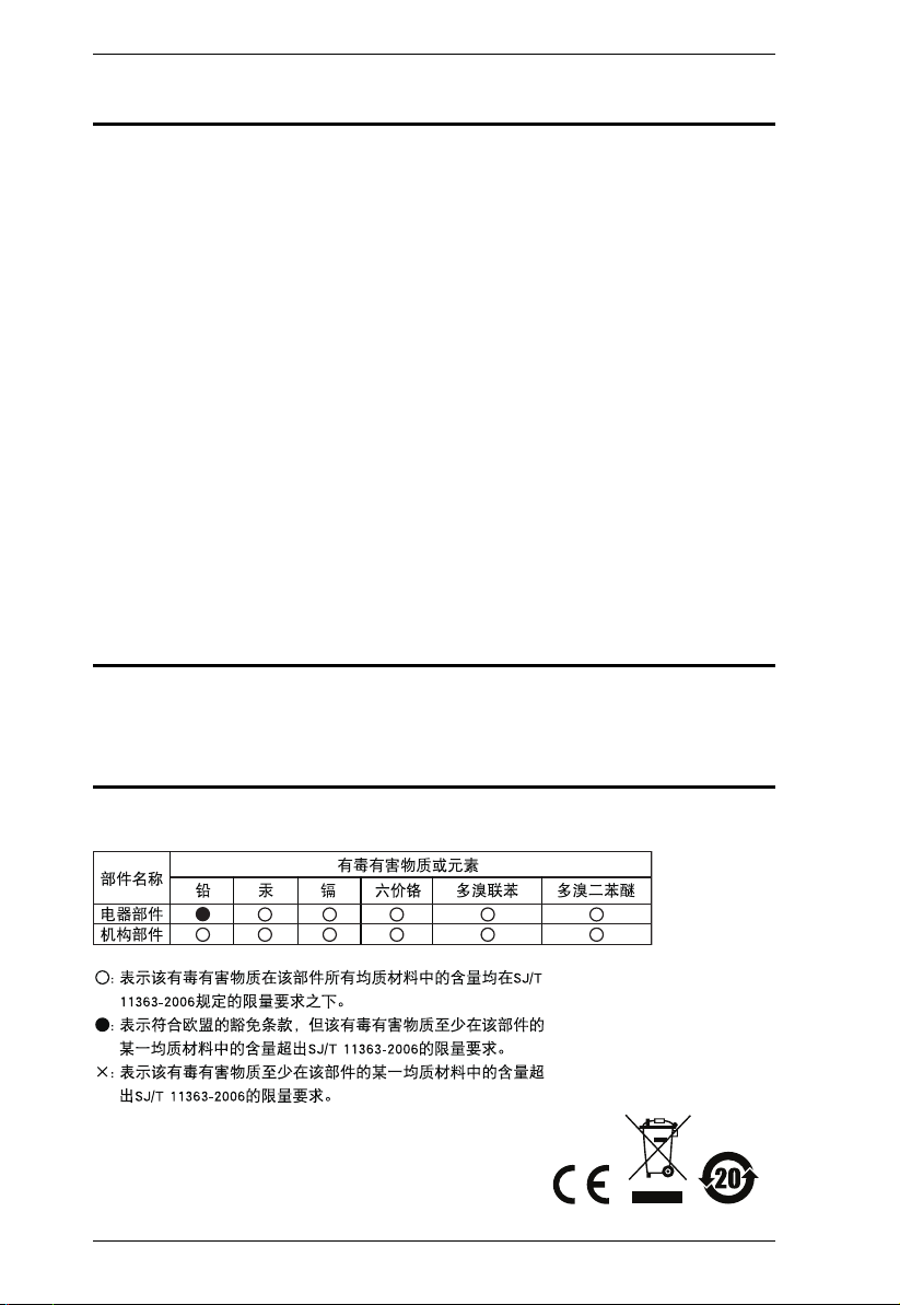
SJ/T 11364-2006. . . . . . . . . . . . . . . . . . . . . . . . . . . . . . . . . . . . . . . . . . . . . ii
User Information . . . . . . . . . . . . . . . . . . . . . . . . . . . . . . . . . . . . . . . . . . . . .iii
Online Registration . . . . . . . . . . . . . . . . . . . . . . . . . . . . . . . . . . . . . . . .iii
Telephone Support . . . . . . . . . . . . . . . . . . . . . . . . . . . . . . . . . . . . . . . .iii
User Notice . . . . . . . . . . . . . . . . . . . . . . . . . . . . . . . . . . . . . . . . . . . . . .iii
PE Device Safety Notice . . . . . . . . . . . . . . . . . . . . . . . . . . . . . . . . . . . .iii
Package Contents . . . . . . . . . . . . . . . . . . . . . . . . . . . . . . . . . . . . . . . . . . iv
Conventions . . . . . . . . . . . . . . . . . . . . . . . . . . . . . . . . . . . . . . . . . . . . . . . ix
Product Information . . . . . . . . . . . . . . . . . . . . . . . . . . . . . . . . . . . . . . . . . . x
Chapter 1.
Introduction
Overview . . . . . . . . . . . . . . . . . . . . . . . . . . . . . . . . . . . . . . . . . . . . . . . . . . . 1
PE7216r / PE7234r / PE8216r / PE8324r / PE9216r / PE9324r Compar-
ison Chart . . . . . . . . . . . . . . . . . . . . . . . . . . . . . . . . . . . . . . . . . . . . . . . 3
Features . . . . . . . . . . . . . . . . . . . . . . . . . . . . . . . . . . . . . . . . . . . . . . . . . . . 4
Power Distribution . . . . . . . . . . . . . . . . . . . . . . . . . . . . . . . . . . . . . . . . 4
Remote Access . . . . . . . . . . . . . . . . . . . . . . . . . . . . . . . . . . . . . . . . . . . 4
Operation. . . . . . . . . . . . . . . . . . . . . . . . . . . . . . . . . . . . . . . . . . . . . . . . 4
Management . . . . . . . . . . . . . . . . . . . . . . . . . . . . . . . . . . . . . . . . . . . . . 5
Security . . . . . . . . . . . . . . . . . . . . . . . . . . . . . . . . . . . . . . . . . . . . . . . . . 5
eco Sensors Energy Management Software* . . . . . . . . . . . . . . . . . . . .6
Proactive Overload Protection (POP) (PE9 series). . . . . . . . . . . . . . . . 6
Requirements . . . . . . . . . . . . . . . . . . . . . . . . . . . . . . . . . . . . . . . . . . . . . . . 7
Optional Accessories . . . . . . . . . . . . . . . . . . . . . . . . . . . . . . . . . . . . . . . . .8
Sensors . . . . . . . . . . . . . . . . . . . . . . . . . . . . . . . . . . . . . . . . . . . . . . . . 8
Cable Holders . . . . . . . . . . . . . . . . . . . . . . . . . . . . . . . . . . . . . . . . . . . . 8
Components . . . . . . . . . . . . . . . . . . . . . . . . . . . . . . . . . . . . . . . . . . . . . . . . 9
PE7216r / PE8216r / PE9216r . . . . . . . . . . . . . . . . . . . . . . . . . . . . . . .9
PE7324r / PE8324r / PE9324r . . . . . . . . . . . . . . . . . . . . . . . . . . . . . .11
Port and LED Panel . . . . . . . . . . . . . . . . . . . . . . . . . . . . . . . . . . . . . .13
Chapter 2.
Hardware Setup
Before You Begin . . . . . . . . . . . . . . . . . . . . . . . . . . . . . . . . . . . . . . . . . . . 15
Rack Mounting . . . . . . . . . . . . . . . . . . . . . . . . . . . . . . . . . . . . . . . . . . . . .15
PDU Placement . . . . . . . . . . . . . . . . . . . . . . . . . . . . . . . . . . . . . . . . . . . . 16
Single Stage Installation . . . . . . . . . . . . . . . . . . . . . . . . . . . . . . . . . . . . . . 17
Single Stage Installation Diagram . . . . . . . . . . . . . . . . . . . . . . . . . . .18
Daisy Chaining . . . . . . . . . . . . . . . . . . . . . . . . . . . . . . . . . . . . . . . . . . . . . 19
Securing the Cables . . . . . . . . . . . . . . . . . . . . . . . . . . . . . . . . . . . . . . 20
Securing the Sensors . . . . . . . . . . . . . . . . . . . . . . . . . . . . . . . . . . . . . 21

eco PDU PE Series User Manual
vi
Chapter 3.
Basic Operation and
First Time Setup
Operation Methods . . . . . . . . . . . . . . . . . . . . . . . . . . . . . . . . . . . . . . . . . . 23
Browser . . . . . . . . . . . . . . . . . . . . . . . . . . . . . . . . . . . . . . . . . . . . . . . 23
eco Sensors . . . . . . . . . . . . . . . . . . . . . . . . . . . . . . . . . . . . . . . . . . . . 23
SNMP . . . . . . . . . . . . . . . . . . . . . . . . . . . . . . . . . . . . . . . . . . . . . . . . . 23
First Time Setup . . . . . . . . . . . . . . . . . . . . . . . . . . . . . . . . . . . . . . . . . . . 24
Network Configuration . . . . . . . . . . . . . . . . . . . . . . . . . . . . . . . . . . . . 25
Changing the Administrator Login . . . . . . . . . . . . . . . . . . . . . . . . . . . 26
Moving On . . . . . . . . . . . . . . . . . . . . . . . . . . . . . . . . . . . . . . . . . . . . . . . . 26
Chapter 4.
Logging In
Logging In . . . . . . . . . . . . . . . . . . . . . . . . . . . . . . . . . . . . . . . . . . . . . . . . . 27
The eco PDU Main Page . . . . . . . . . . . . . . . . . . . . . . . . . . . . . . . . . . . . . 28
Page Components . . . . . . . . . . . . . . . . . . . . . . . . . . . . . . . . . . . . . . . 29
Chapter 5.
Outlet Access
Outlet Access . . . . . . . . . . . . . . . . . . . . . . . . . . . . . . . . . . . . . . . . . . . . . . 31
Connections . . . . . . . . . . . . . . . . . . . . . . . . . . . . . . . . . . . . . . . . . . . . 31
Station Level . . . . . . . . . . . . . . . . . . . . . . . . . . . . . . . . . . . . . . . . . . . 32
Outlet Level . . . . . . . . . . . . . . . . . . . . . . . . . . . . . . . . . . . . . . . . . . . . 34
Outlet Group Level . . . . . . . . . . . . . . . . . . . . . . . . . . . . . . . . . . . . . . . 36
User Preferences . . . . . . . . . . . . . . . . . . . . . . . . . . . . . . . . . . . . . . . . 37
Sessions . . . . . . . . . . . . . . . . . . . . . . . . . . . . . . . . . . . . . . . . . . . . . . . 38
Access . . . . . . . . . . . . . . . . . . . . . . . . . . . . . . . . . . . . . . . . . . . . . . . . 38
Outlet Level . . . . . . . . . . . . . . . . . . . . . . . . . . . . . . . . . . . . . . . . . . . . 39
Configuration . . . . . . . . . . . . . . . . . . . . . . . . . . . . . . . . . . . . . . . . . . . 40
Outlet Level Configuration . . . . . . . . . . . . . . . . . . . . . . . . . . . . . . . . . 44
Chapter 6.
User Management
Overview. . . . . . . . . . . . . . . . . . . . . . . . . . . . . . . . . . . . . . . . . . . . . . . . . . 49
Users . . . . . . . . . . . . . . . . . . . . . . . . . . . . . . . . . . . . . . . . . . . . . . . . . . . . 50
Adding Users . . . . . . . . . . . . . . . . . . . . . . . . . . . . . . . . . . . . . . . . . . . 50
Modifying User Accounts . . . . . . . . . . . . . . . . . . . . . . . . . . . . . . . . . . 53
Deleting User Accounts . . . . . . . . . . . . . . . . . . . . . . . . . . . . . . . . . . . 53
Moving On . . . . . . . . . . . . . . . . . . . . . . . . . . . . . . . . . . . . . . . . . . . . . 53
Groups . . . . . . . . . . . . . . . . . . . . . . . . . . . . . . . . . . . . . . . . . . . . . . . . . . . 54
Creating Groups . . . . . . . . . . . . . . . . . . . . . . . . . . . . . . . . . . . . . . . . . 54
Modifying Groups . . . . . . . . . . . . . . . . . . . . . . . . . . . . . . . . . . . . . . . . 56
Deleting Groups . . . . . . . . . . . . . . . . . . . . . . . . . . . . . . . . . . . . . . . . . 56
Users and Groups . . . . . . . . . . . . . . . . . . . . . . . . . . . . . . . . . . . . . . . . . . 57
Assigning Users to a Group From the Accounts Page . . . . . . . . . . . . 57

eco PDU PE Series User Manual
vii
Removing Users From a Group From the Accounts Page . . . . . . . . . 58
Assigning Users to a Group From the Groups Page . . . . . . . . . . . . . 59
Removing Users From a Group From the Groups Page . . . . . . . . . . 60
Device Assignment . . . . . . . . . . . . . . . . . . . . . . . . . . . . . . . . . . . . . . . . . 61
Assigning Device Permissions From the Accounts Menu . . . . . . . . . . 61
Assigning Device Permissions From the Groups Page . . . . . . . . . . . 62
Chapter 7.
Device Management
Device Management . . . . . . . . . . . . . . . . . . . . . . . . . . . . . . . . . . . . . . . . . 63
Device Configuration . . . . . . . . . . . . . . . . . . . . . . . . . . . . . . . . . . . . . . 63
Date/Time . . . . . . . . . . . . . . . . . . . . . . . . . . . . . . . . . . . . . . . . . . . . . . 69
Security . . . . . . . . . . . . . . . . . . . . . . . . . . . . . . . . . . . . . . . . . . . . . . . . . . 71
Login String . . . . . . . . . . . . . . . . . . . . . . . . . . . . . . . . . . . . . . . . . . . . . 72
IP and MAC Filtering . . . . . . . . . . . . . . . . . . . . . . . . . . . . . . . . . . . . . 72
Account Policy . . . . . . . . . . . . . . . . . . . . . . . . . . . . . . . . . . . . . . . . . . 75
Login String / IP Filter / Mac Filter . . . . . . . . . . . . . . . . . . . . . . . . . . . 76
Authentication & Authorization . . . . . . . . . . . . . . . . . . . . . . . . . . . . . . 79
Private Certificate . . . . . . . . . . . . . . . . . . . . . . . . . . . . . . . . . . . . . . . . 81
Chapter 8.
Log
Log . . . . . . . . . . . . . . . . . . . . . . . . . . . . . . . . . . . . . . . . . . . . . . . . . . . . . . 83
The System Log Event List . . . . . . . . . . . . . . . . . . . . . . . . . . . . . . . . 84
Notification Settings . . . . . . . . . . . . . . . . . . . . . . . . . . . . . . . . . . . . . . . . . 85
Chapter 9.
Maintenance
Maintenance . . . . . . . . . . . . . . . . . . . . . . . . . . . . . . . . . . . . . . . . . . . . . . . 87
Firmware File. . . . . . . . . . . . . . . . . . . . . . . . . . . . . . . . . . . . . . . . . . . . 87
Backup/Restore . . . . . . . . . . . . . . . . . . . . . . . . . . . . . . . . . . . . . . . . . 89
Chapter 10.
Remote Terminal Operation
Overview . . . . . . . . . . . . . . . . . . . . . . . . . . . . . . . . . . . . . . . . . . . . . . . . . . 91
Telnet . . . . . . . . . . . . . . . . . . . . . . . . . . . . . . . . . . . . . . . . . . . . . . . . . . . . 91
Logging In . . . . . . . . . . . . . . . . . . . . . . . . . . . . . . . . . . . . . . . . . . . . . . 91
SSH . . . . . . . . . . . . . . . . . . . . . . . . . . . . . . . . . . . . . . . . . . . . . . . . . . . . . 93
Terminal Session (Linux): . . . . . . . . . . . . . . . . . . . . . . . . . . . . . . . . . . 93
Third Party Utility (Windows): . . . . . . . . . . . . . . . . . . . . . . . . . . . . . . . 94
Appendix
Safety Instructions. . . . . . . . . . . . . . . . . . . . . . . . . . . . . . . . . . . . . . . . . . . 95
General . . . . . . . . . . . . . . . . . . . . . . . . . . . . . . . . . . . . . . . . . . . . . . . . 95
Rack Mounting . . . . . . . . . . . . . . . . . . . . . . . . . . . . . . . . . . . . . . . . . . 97
The eco PDU’s Main Power Cord . . . . . . . . . . . . . . . . . . . . . . . . . . . 97
Securing the Power Cables . . . . . . . . . . . . . . . . . . . . . . . . . . . . . . . . 97

eco PDU PE Series User Manual
viii
Technical Support . . . . . . . . . . . . . . . . . . . . . . . . . . . . . . . . . . . . . . . . . . 98
International . . . . . . . . . . . . . . . . . . . . . . . . . . . . . . . . . . . . . . . . . . . . 98
North America . . . . . . . . . . . . . . . . . . . . . . . . . . . . . . . . . . . . . . . . . . 98
IP Address Determination . . . . . . . . . . . . . . . . . . . . . . . . . . . . . . . . . . . . 99
Specifications . . . . . . . . . . . . . . . . . . . . . . . . . . . . . . . . . . . . . . . . . . . . . 101
Basic Comparison . . . . . . . . . . . . . . . . . . . . . . . . . . . . . . . . . . . . . . . 101
PE7216rB / PE8216rB / PE9216rB . . . . . . . . . . . . . . . . . . . . . . . . . 102
PE7216rG / PE8216rG / PE9216rG . . . . . . . . . . . . . . . . . . . . . . . . . 103
PE7324rB/rJ/ PE8324rB/rJ / PE9324rB/rJ . . . . . . . . . . . . . . . . . . . . 104
PE7324rG / PE8324rG / PE9324rG . . . . . . . . . . . . . . . . . . . . . . . . . 105
Administrator Login Failure . . . . . . . . . . . . . . . . . . . . . . . . . . . . . . . . . . 106
Limited Warranty . . . . . . . . . . . . . . . . . . . . . . . . . . . . . . . . . . . . . . . . . . 107

eco PDU PE Series User Manual
ix
Conventions
This manual uses the following conventions:
Monospaced Indicates text that you should key in.
[ ] Indicates keys you should press. For example, [Enter] means
to press the Enter key. If keys need to be chorded, they
appear together in the same bracket with a plus sign
between them: [Ctrl+Alt].
1. Numbered lists represent procedures with sequential steps.
♦Bullet lists provide information, but do not involve sequential
steps.
→Indicates selecting the option (on a menu or dialog box, for
example), that comes next. For example, Start →Run
means to open the Start menu, and then select Run.
Indicates critical information.

eco PDU PE Series User Manual
x
Product Information
For information about all NRGence products and how they can help you save
money in the data center, visit NRGence on the Web or contact an ATEN
Authorized Reseller. Visit ATEN on the Web for a list of locations and
telephone numbers
International – http://www.aten.com
North America – http://www.aten-usa.com

1
Chapter 1
Introduction
Overview
As part of its NRGence line, ATEN has developed a new generation of green
energy power distribution units (eco PDUs) to effectively increase the
efficiency of data center power usage. The NRGence PE7216r / PE7234r /
PE8216r / PE8324r / PE9216r / PE9324r eco PDUs are intelligent PDUs that
contain 16 or 24 AC outlets and are available in various IEC or NEMA socket
configurations. Models in the advanced PE9 range feature a dedicated 8-outlet
bank for critical load devices, as well as NRGence’s proactive overload
protection, which automatically powers off the last outlet that caused the
current overload.
NRGence eco PDUs provide secure, centralized, intelligent, power
management (power on, off, cycle) of data center IT equipment (servers,
storage systems, KVM switches, network devices, serial data devices, etc.), as
well as the ability to monitor the center's health environment via sensors*. The
basic characteristics of each model are shown in the table on page 3.
NRGence eco PDUs offer remote power control combined with real-time
power measurement – allowing you to control and monitor the power status of
devices attached to the PDUs, either at the PDU device, bank, or outlet level,
depending on the model, from practically any location via a TCP/IP
connection*.
The power status of each outlet can be set individually, allowing users to switch
each device On/Off. The eco PDU also offers comprehensive power analysis
reports which can separate departments and locations, providing precise
measurements of current, voltage, power and watt-hour in a real-time display.
Installation and operation is fast and easy: plugging cables into their
appropriate ports and user-friendly browser-based configuration and
management is all that is entailed. Since the eco PDU firmware is upgradeable
over the Net, you can stay current with the latest functionality improvements
simply by downloading updates from our website as they become available.
NRGence eco PDU supports any 3rd party V1, V2, V3 SNMP Manager
Software and NRGence eco Sensors (eco PDU Manager Software). eco
Sensors provides you with an easy method for managing multiple devices,
offering an intuitive and user-friendly Graphical User Interface that allows you

eco PDU PE Series User Manual
2
to configure a PDU device and monitor power status of the equipment
connected to it.
With its advanced security features and ease of operation, the eco PDU is the
most convenient, most reliable, and most cost effective way to remotely
manage power access for multiple computer installations and allocate power
resources in the most efficient way possible.
Note: 1. Sensors are optional accessories. A sensor-enabled installation is
required to generate a more complete energy-efficient data and chart.
Higher sensor installation density is helpful to generate more accurate
data. See Optional Accessories, page 8, for further information.
2. eco PDUs are primarily designed for access via Intranet; extra
network security protection is suggested for Internet access usage.
3. Not all models support all features. See PE7216r / PE7234r /
PE8216r / PE8324r / PE9216r / PE9324r Comparison Chart, page 3,
and Specifications, page 101, for full details.

Chapter 1. Introduction
3
PE7216r / PE7234r / PE8216r / PE8324r / PE9216r / PE9324r
Comparison Chart
Note: For the complete specifications of individual models, including bank-
by-bank outlet details, please reference Specifications, page 101.
Model Inlet / Cord Outlets Metering
Level
Outlet
Switching
PE7216rB NEMA 6-20P 16 14 x IEC 320 C13 +
2 x IEC 320 C19
PDU /
1 x Bank /
Outlet
No
PE8216rB Yes 16/16
PE9216rB Yes 8/16
PE7216rG IEC 60320 C20 No
PE8216rG Yes 16/16
PE9216rG Yes 8/16
PE7324rB /
PE7324rJ
NEMA L6-30P 24 21 x IEC 320 C13 +
3 x IEC 320 C19
PDU /
2 x Bank /
Outlet
No
PE8324rB /
PE8324rJ
Yes 24/24
PE9324rB /
PE9324rJ
Yes 16/24
PE7324rG IEC 60309 32A No
PE8324rG Yes 24/24
PE9324rG Yes 16/24

eco PDU PE Series User Manual
4
Features
Power Distribution
Space saving 0U rack mount design with rear mounting
IEC or NEMA outlet models
2 digit 7-segment front panel LED shows Station / Bank / Outlet ID
3 digit 7-segment front panel LED shows Current / Voltage / Power
Dissipation and readings from up to 4 environment sensors
Safe shutdown support
Daisy chain up to 5 additional stations
Separate power for the unit's own power and its power outlets – the user
interface is still accessible even when an overload condition trips the
devices' circuit breaker
Dedicated 8-outlet bank for critical load devices (PE9 models only) –
always powered on
Proactive overload protection (POP) (PE8 and PE9 models only) –
automatically powers off the last outlet that caused the current overload
(see Proactive Overload Protection (POP) (PE9 series), page 6)
Remote Access
Remote power control via TCP/IP and a built in 10/100 Ethernet port
Network Protocols: TCP/IP, UDP, HTTP, HTTPS, SSL, SMTP, DHCP,
NTP, DNS, auto sense, Ping
Out of Band operation via modem access
Remote users can monitor outlet status via web pages on their browsers
eco PDU Power Management software – eco Sensors
Supports SNMP Manager V1, V2 & V3
Operation
Remote power outlet control (On, Off, Power Cycle) by individual outlets
(PE8 / PE9 models)
Outlet group support – the same action can be performed on specified
groups of outlets at the same time
Supports multiple power control methods – Wake on LAN, System after
AC Back, Kill the Power

Chapter 1. Introduction
5
Power-on sequencing – set the power on sequence and delay time for each
outlet to allow equipment to be powered on in the correct order
Easy setup and operation via a browser-based user interface
Multibrowser support (IE, Mozilla, Firefox, Chrome, Safari, Opera,
Netscape)
RTC support to keep the timer running during times of no power
Up to 8 user accounts and 1 administrator account
Management
Power metering and monitoring at the PDU / Bank / Outlet level
LED indicators for current, voltage, power dissipation at the PDU / Bank /
Outlet levels
Real-time aggregate current, voltage, and power and power dissipation
displayed in a browser-based UI for monitoring at the PDU, bank and
outlet level (16-port models offer 1 bank metering; 24-port models offer 2
bank metering)
Alert notification for selected events (On, Off, Recycle, Failure, exceeding
threshold settings, etc.), via blinking LEDs (locally), SMTP, SNMP trap
notification, and digital output
Supports Management Information Base (MIB) files for SNMP
Environment monitoring – supports external temperature / humidity /
differential pressure sensors for rack environment monitoring
Current and voltage threshold setting
Naming support for outlets and outlet groups
User outlet access assignment on an outlet-by-outlet basis
Event logging and syslog support
Upgradeable firmware
Multilanguage support – English, Traditional Chinese, Simplified
Chinese, Japanese, German, Italian, Spanish, French, Russian, Korean,
Portuguese
Security
Two-level password security
Strong security features include strong password protection and advanced
encryption technologies – 128 bit SSL
Remote authentication support: RADIUS

eco PDU PE Series User Manual
6
eco Sensors Energy Management Software*
Automatic discovery of all PE devices within the same intranet
Remote real-time power measurement and monitoring
Real-time environment sensor monitoring
Plotting/monitoring of all PE devices
Exceed threshold alert through SMTP and System log
Power Analysis report
Note: eco Sensors is designed to work with NRGence PDUs, and is bundled
with all PE series packages.
Proactive Overload Protection (POP) (PE9 series)
The PE9216r and PE9324r models feature NRGence’s exclusive Proactive
Overload Protection (POP) technology. Effective on outlets 9–16, this added
safety feature automatically powers off the last outlet that caused the current
overload.
POP mode is engaged when the Bank 1 current exceeds the set threshold
maximum value, powering off the outlet. The LED display shows POP and a
beeper sounds. Press any button for two seconds to clear POP modem and
power the outlet back on.

Chapter 1. Introduction
7
Requirements
Browsers accessing the eco PDU unit must support SSL 128 bit
encryption.
For cold booting of attached computers, the computer's BIOS must
support Wake on LAN or System after AC Back.
For Safe Shutdown:
The computer must be running Windows (Windows 2000 or higher) or
Linux.
The Safe Shutdown program (available by download from our website
or on the software CD included), must be installed and running on the
computer.

eco PDU PE Series User Manual
8
Optional Accessories
Sensors
For complete energy management of an instrumented data center with the use
of the eco PDU and eco Sensors software, you should install 4 sensors for each
of the racks in your data center in order to generate a complete energy-efficient
data chart. Higher sensor installation density is helpful to generate more
accurate data. 8/16-port models have 4 sensor ports. Higher sensor installation
density is helpful to generate more accurate data.
To get the most complete eco Sensors Dashboard data, the recommended 4-
sensor setup is show in the table, below:
Sensor Management
Sensors can be managed via the eco PDU’s built-in graphical user interface
(GUI) or with the NRGence eco Sensors software that can be downloaded from
the ATEN website. The download link can be found on the software CD
provided with the eco PDU package.
Cable Holders
Cable holders are optional accessories. For added safety, use ATEN Lok-U-
Plug cable holders to secure the cables from your attached devices in place on
the eco PDU unit. Use only the ATEN Lok-U-Plug cable holders that have
been specifically designed to work with the eco PDU. Using any other kind of
cable securing device could be highly dangerous.
Port Location Part Number Sensor
Sensor 1 Intake EA1140 or
EA1240
Temperature or
Temperature / Humidity
Sensor 2 Intake
Sensor 3 Exhaust
Sensor 4 Exhaust
or Floor EA1340 Differential Pressure
Part Number Description
2X-EA07 Lok-U-Plug Cable Holder (10 pcs)
2X-EA08 Lok-U-Plug Installation Tool (4 pcs)

Chapter 1. Introduction
9
Components
PE7216r / PE8216r / PE9216r
Note: The PE7216r / PE8216r / PE9216r unit components are identical except
for the outlet LEDs – the PE7216r has none; the PE8216r has 16; and
the PE9216r has 8, as shown by number 9 above.
1
2
5
3
4
155
PE7216r PE8216r PE9216r

eco PDU PE Series User Manual
10
Note: Holes for ATEN Lok-U-Plug cable holders are located around the
outlets. See Securing the Cables, page 20, for further information.
No. Item Description
1 Power Outlets* 16 in total (14 x IEC 320 C13 + 2 x IEC 320 C19)
Bank 1-1: Outlet 1–8: 7 C13; 1 x C19
Bank 1-2: Outlet 9–16: 7 x C13; 1 x C19
2 Port and LED Panel The Port and LED panel contains:
Readout Section and LEDs
Sensor Ports
LAN and Modem Ports
Console/PON In and PON Out Ports
Digital Output Port
Reset Switch
Full details of this section are provided on
page 13.
3 Circuit Breaker
Pushbutton
As a safety measure, if there is an overcurrent
situation regarding the device’s power, the circuit
breakers will trip. Press the button to recover
normal operation.
4 Power Inlet The power cord that connects the unit to an AC
power source plugs into this socket.
B models connect to a NEMA 6-20P source
G models connect to an IEC 60309 32A source
5 Outlet Status LEDs PE8216r (x 16) and PE9216r (x 8) only.
These LEDs indicate outlet status.
Lights ORANGE for powered on.
Off for powered off.
This manual suits for next models
5
Table of contents
Other ATEN Power Distribution Unit manuals

ATEN
ATEN PG98230 Series User manual

ATEN
ATEN PE1216 User manual

ATEN
ATEN Altusen PN7212 User manual

ATEN
ATEN PE7216 User manual

ATEN
ATEN NRGence PE5108 User manual

ATEN
ATEN NRGence PE Series User manual

ATEN
ATEN eco PDU PE5216 User manual

ATEN
ATEN PE5216 User manual

ATEN
ATEN PE4104G User manual

ATEN
ATEN PE7216 User manual

ATEN
ATEN NRGence PE5-8108 User manual

ATEN
ATEN PE5220s User manual

ATEN
ATEN NRGence PE5-8108 User manual

ATEN
ATEN NRGence PE5108 User manual

ATEN
ATEN PG Series User manual

ATEN
ATEN PE5340SL User manual

ATEN
ATEN eco PDU PE Series User manual

ATEN
ATEN NRGence PE5221T User manual

ATEN
ATEN PE Series User manual

ATEN
ATEN NRGence PE0112 User manual