manuals.online logo
Brands
  1. Home
  2. •
  3. Brands
  4. •
  5. Atmel
  6. •
  7. Microcontroller
  8. •
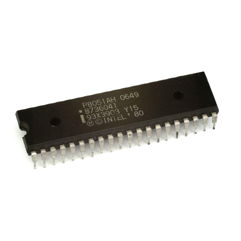
  9. Atmel 80C51 Installation and operating instructions

Atmel 80C51 Installation and operating instructions

Other manuals for 80C51

1

Other Atmel Microcontroller manuals

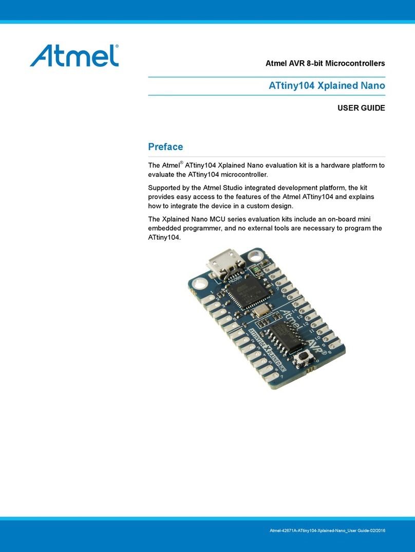
Atmel ATtiny104 Xplained Nano User manual
Atmel

Atmel ATtiny104 Xplained Nano User manual

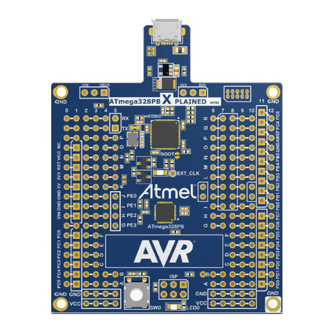
Atmel ATmega328PB Xplained Mini Installation and operating instructions
Atmel

Atmel ATmega328PB Xplained Mini Installation and operating instructions

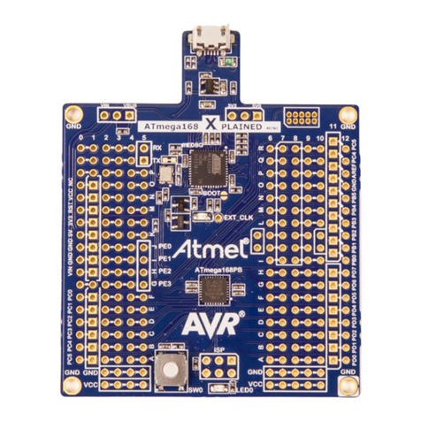
Atmel ATmega168PB Xplained Mini User manual
Atmel

Atmel ATmega168PB Xplained Mini User manual

Atmel 8051 User manual

Atmel

Atmel 8051 User manual
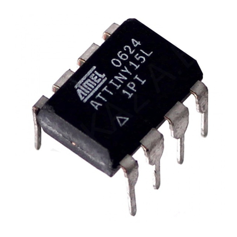
Atmel AVR ATtiny15L User manual

Atmel

Atmel AVR ATtiny15L User manual
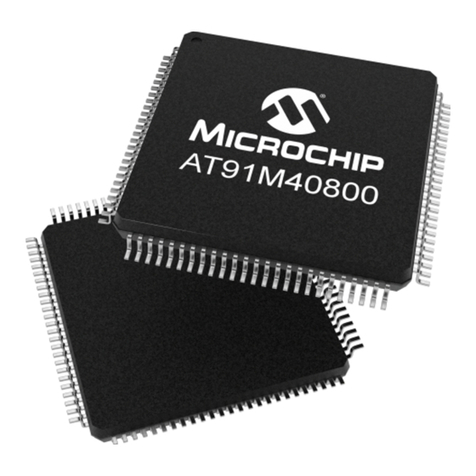
Atmel AT91 Series User manual

Atmel

Atmel AT91 Series User manual
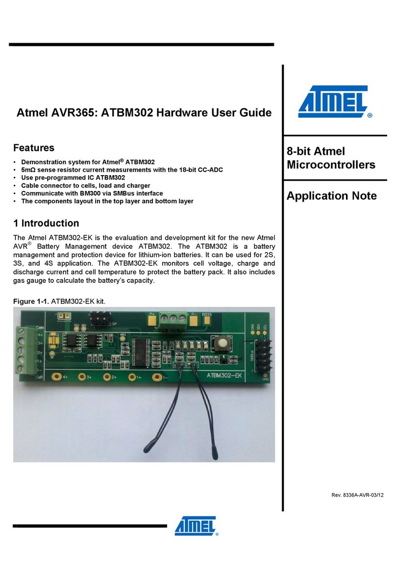
Atmel AVR365 User manual

Atmel

Atmel AVR365 User manual
Atmel AT89STK-03 Installation manual

Atmel

Atmel AT89STK-03 Installation manual
Atmel AT90PWM2 User manual

Atmel

Atmel AT90PWM2 User manual
Atmel AVR ATtiny22 Instruction Manual

Atmel

Atmel AVR ATtiny22 Instruction Manual

Atmel AT43DK325 User manual

Atmel

Atmel AT43DK325 User manual
Atmel AT89RFD-10/EVLB002 User manual

Atmel

Atmel AT89RFD-10/EVLB002 User manual
Atmel AT18F-DK3 User manual

Atmel

Atmel AT18F-DK3 User manual
Atmel AVR042 Installation and operating instructions
Atmel

Atmel AVR042 Installation and operating instructions

Atmel ATmega32M1 User manual

Atmel

Atmel ATmega32M1 User manual

Atmel AT90USB162 User manual

Atmel

Atmel AT90USB162 User manual
Atmel AT90S4433-8AC User manual

Atmel

Atmel AT90S4433-8AC User manual
Atmel QTouch Installation and operating instructions

Atmel

Atmel QTouch Installation and operating instructions

Atmel ATF15 DK2 Series User manual

Atmel

Atmel ATF15 DK2 Series User manual
Atmel AVR32 STK1000 User manual

Atmel

Atmel AVR32 STK1000 User manual

Atmel AVR180 Installation and operating instructions

Atmel

Atmel AVR180 Installation and operating instructions

Atmel AVR2060 User manual

Atmel

Atmel AVR2060 User manual

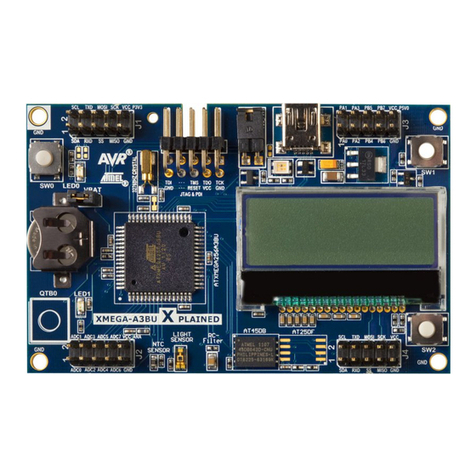
Atmel AVR XMEGA-A3BU Installation and operating instructions

Atmel

Atmel AVR XMEGA-A3BU Installation and operating instructions

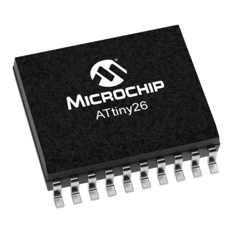
Atmel ATtiny26 User manual

Atmel

Atmel ATtiny26 User manual

Popular Microcontroller manuals by other brands

Microsemi IGLOO nano Starter Kit user guide

Microsemi

Microsemi IGLOO nano Starter Kit user guide

GOWIN DK START GW1NSR-LV4CQN48PC7I6 V 1.1 user guide

GOWIN

GOWIN DK START GW1NSR-LV4CQN48PC7I6 V 1.1 user guide

HETRONIC ERGO-S Service manual

HETRONIC

HETRONIC ERGO-S Service manual

Laird BL654PA user guide

Laird

Laird BL654PA user guide

Novatek NT6861 manual

Novatek

Novatek NT6861 manual

Lantronix Intrinsyc Open-Q 865XR SOM user guide

Lantronix

Lantronix Intrinsyc Open-Q 865XR SOM user guide

Nuvoton ISD61S00 ChipCorder Design guide

Nuvoton

Nuvoton ISD61S00 ChipCorder Design guide

STMicrolectronics ST7 Assembler Linker user manual

STMicrolectronics

STMicrolectronics ST7 Assembler Linker user manual

Texas Instruments Chipcon CC2420DK user manual

Texas Instruments

Texas Instruments Chipcon CC2420DK user manual

NEC 78GK0S/K 1+ Series Application note

NEC

NEC 78GK0S/K 1+ Series Application note

Mikroe SEMITECH N-PLC Click Application note

Mikroe

Mikroe SEMITECH N-PLC Click Application note

Intel Agilex user guide

Intel

Intel Agilex user guide

DIGITAL-LOGIC MICROSPACE manual

DIGITAL-LOGIC

DIGITAL-LOGIC MICROSPACE manual

Texas Instruments TMS320F2837 D Series Workshop Guide and Lab Manual

Texas Instruments

Texas Instruments TMS320F2837 D Series Workshop Guide and Lab Manual

CYPRES CY14NVSRAMKIT-001 user guide

CYPRES

CYPRES CY14NVSRAMKIT-001 user guide

Espressif Systems ESP8266EX Programming guide

Espressif Systems

Espressif Systems ESP8266EX Programming guide

Abov AC33M8128L user manual

Abov

Abov AC33M8128L user manual

Silicon Laboratories C8051F800 user guide

Silicon Laboratories

Silicon Laboratories C8051F800 user guide
manuals.online logo
manuals.online logoBrands
  • About & Mission
  • Contact us
  • Privacy Policy
  • Terms and Conditions

Copyright 2025 Manuals.Online. All Rights Reserved.

1
Analyzing the Behavior of an Oscillator and
Ensuring Good Start-up
This application note explains how an oscillator functions and which methods can be
used to check if the oscillation conditions are met in order to ensure a good start-up
when power is applied.
Oscillator Fundamentals
A microcontroller integrates on-chip an oscillator to generate a stable clock used to
synchronize the CPU and the peripherals.
Figure 1. Basic Oscillator Architecture
The basic architecture of an oscillator (regardless of its structure) is shown in Figure 1
and built around an amplifier, a feed-back and noise applied on Xtal1 input. The role of
each elements is explained hereafter:
•Amplifier: Used to amplify the signal applied on Xtal1 and to lock the oscillations
exhibit Xtal2. The class A structure is the most popular but new ones are currently
used in order to optimize the consumption or other criterion,
•Feed-back loop: Used to filter the output signal and to send it to the Xtal1 input.
The oscillator stability is linked to the bandwidth of the loop. The narrower the
filter, the more stable the oscillator. Crystals or ceramic resonators are generally
used because they have the narrowest bandwidth and efficiency for the stability of
the frequency.
Amplifier
Feed-back
Loop
Noise +G(f)
H(f)
Xtal1 Xtal2
80C51 MCU’s
ApplicationNote
Rev. 4363A–80C51–07/04
24363A–80C51–07/04
•Noise: Thanks to the noise an oscillator is able to startup. This noise has different
origins:
–thermal noise due to the transistor junctions and resistors,
–RF noise: a wide band noise is present in the air and consequently on all the
pins of the chip and in particular on Xtal1 input of the amplifier. The noise
origin can be industrial, astronomic, semiconductor, ...
–transient noise during the power-up.
The noise is coupled to the amplifier from the inside and outside of the chip through the
package, the internal power rails, ....
Figure 2 shows the typical oscillator structure used in most microcontroller chips. An on-
chip amplifier connected to an external feed-back consists in a crystal or a resonator
and two capacitors (a). Sometimes a resistor is inserted (b) between the amplifier output
and the crystal in order to limit the power applied, avoiding the destruction of the crystal.
Figure 2. Typical Oscillator Structures
a) b)
Xtal1 Xtal2 Xtal1 Xtal2
3
4363A–80C51–07/04
Typical Oscillator
Operation The process involved in start-up and locking of oscillator is explained hereafter (see Fig-
ure 3):
•Biasing process. The power-up is applied and the amplifier output follows the
power until it reaches its biasing level where it can amplify the noise signal on its
input.
•Oscillation. The amplified noise on the output (Xtal2) is filtered by the feed-back
loop which has a pass-band frequency corresponding to the nominal oscillator
frequency. The filtered output noise is amplified again and starts to increase. The
oscillation level continue to grow and reaches the non-linear area.
•Lock. In the non-linear area both the gain and the oscillation level starts to reduce.
•Steady State. A stabilization point is found where the closed-loop gain is
maintained with the unity.
Figure 3. Process Needed to Reach a Stable Oscillation
Each element plays a role and their electrical characteristics have to be understood. The
next sections explain this matter.
Crystal Model and
Operation Crystal and ceramic resonators are piezoelectric devices which transform voltage
energy to mechanical vibrations and vice-versa. At certain vibrational frequencies, there
is a mechanical resonance. Main resonances are called: fundamental, third, fifth, ...
overtones. Overtones are not harmonics but different mechanical vibrational modes.
This crystal is an efficient pass-band filter which exhibits a good frequency stability. The
equivalent model, shown in Figure 4, consists of two resonant circuits:
•C1,L1 and R1 is a series resonant circuit (fs),
• In addition the series circuit, C0 in parallel forms a parallel circuit which has a
parallel resonance frequency (fa) .
Vxtal2
Start Oscillation Steady State
VDD
t
Lock
Biasing
Bias Level
44363A–80C51–07/04
Figure 4. Crystal Models.
Figure 5 plots the module and phase of the impedance crystal and shows both the
series and parallel resonance frequencies.
Figure 5. Phase and Module Versus the Frequency
The behavior of the crystal depends on the frequency and is summarized in Table 1.
Table 1. Nature of the Impedance Versus the Frequency
Frequency f < fs f=fs fs < f < fa f=fa f>fa
Z(f) Capacitive
C1 Resistance
R1 Inductive
L1 Resistance
Rp Capacitive
C0
Phase(°) -90 0 +90 0-90
Q2Q1 R1 L1 C1
C0
9.998
.
10
6
9.999
.
10
6
1
.
10
7
1.0001
.
10
7
1.0002
.
10
7
1.0003
.
10
7
1.0004
.
10
7
1.0005
.
10
0
25
50
75
100
9
6.034
0
f()
)
11
×
9.998 10
6
⋅
f
6 6 7 7 7 7 7 7
90
45
0
45
90
90
90
−
)) 360
6.28
⋅
Parallel
Z(f)
dB
φ(f)
d
egree
f
f
C1
R1
L1
Rp C0
fs
fa
Series
fs 1
6.28 C1 L1
⋅⋅
:=
fa fs 1 C1
C0
+⋅:=
5
4363A–80C51–07/04
The impedance phase is related to the frequency and each elements of the model plays
a role in specific frequency ranges. The main electrical characteristics of these elements
are summarized hereafter.
Table 2 gives some typical crystal characteristics.
Note: 1. Fundamental Mode
2. Third Overtone Mode
“Series” Versus
“Parallel” Crystal There is no such thing as a “series cut” crystal as opposed to a “parallel cut” crystal.
Both modes exist in a crystal. Only the oscillator structures (Pierce, Colpitts, ..) will oscil-
late the crystal close to the fs or between fs and fa resonance frequencies. The first
structure is called a series resonant oscillator and the second a parallel resonant
oscillator. It should be noted that no oscillator structure is able to oscillate at the exact
fa frequency. This is due to the high quality factor at fa and the difficulty to stabilize an
oscillator at this frequency.
Table 2. Examples of Crystal Characteristics
Frequency
MHz R1
ohms L1
mH C1
fF C0
pF fs
MHz fp
MHz Qs Qp
32 35 11.25 2.2 7 32 32.005 646k 3.11
30(2) 20 11 2.6 6 30 30.0065 102k 6.14
30(1) 40 33.94 0.83 3.8 30 30.00328 160k 3.48
20 50 20 3.2 10 20 20.0032 497k 2.98
16 80 11.641 8.5 3 16 16.022 146k 3.42
10 20 0.025 10 20 10 10.00025 159.2k 80
8 7 0.0862 4.6 40 8 8.00026 618k 17.4
6 8 0.0848 8.3 40 6 6.000356 533k 37
2 100 520 12 4 2 2.003 66K 198
fs 1
6.28 C1 L1
⋅⋅
:=
Series resonance
frequency Quality factor
Qs L1 6.28
⋅
fs
⋅
R1
:=
Parallel resonance
frequency Quality factor
ESR
Qp 1
C0 6.28
⋅
fp
⋅
R1
⋅
:=
fa fs 1 C1
C0
+⋅:=
ESR R1 1 C0
CL
+





2
⋅:=
fp fs 1 C1
2C0 CL
+
()
⋅
+





⋅:=
Qp 1
CL 6.28
⋅
fp
⋅
ESR
⋅
:=
With External Load, CL
frequency
Quality factor
64363A–80C51–07/04
Overtone or
Fundamental Mode Vibrational mode is used to reduce the crystal cost. Above 20MHz it is costly to produce
such crystals tuned on the fundamental mode. To avoid that, an overtone mode is used
to tune the oscillation frequency. To work properly, this vibrational mode needs a spe-
cific schematic where a frequency trap is installed on the oscillator output to short-circuit
the fundamental mode and force the overtone mode. The trap is an LC filter installed
between the Xtal2 and the ground. The frequency on this filter is calculated on the fun-
damental mode using the Thomson equation (see Figure 6).
Figure 6. A LC trap is Used for an Overtone Oscillator
Drive Level The characteristics of quartz crystals are influenced by the drive level. In particular,
when the drive level increases, the frequency and the resistance change through non-
linear effects. In extreme cases an inharmonic mode may replace the main mode as the
selective element and cause the frequency of the oscillator jump to a different fre-
quency. With an overdrive level, the crystal substrate itself may be damaged. Typical
characteristic of frequency vs. drive levels is shown in Figure 7.
Figure 7. Frequency Shift vs. Drive Level
Drive level is a measurement of the total power dissipated through the crystal operating
in the circuit. Typical drive levels are between 50 uW and 1000 uW (1 mW). Drive levels
should be kept at the minimum level that will initiate and maintain oscillation. It should be
less than half of the maximum drive level. Excessive drive may cause correlation difficul-
ties, frequency drift, spurious emissions, "ringing" wave forms, excessive ageing, and/or
fatal structural damage to the crystal.
Ftrap
1
2π×
Ltrap Ctrap
××
-----------------------------------------------------------=
0
X1
C1 C2 Ctrap
Ltrap
Xtal1 Xtal2
7
4363A–80C51–07/04
The maximum drive, PMax, is specified by the crystal manufacturer. The maximum
RMS current which can flow in the crystal and it is given by the following expression:
where ESR is equivalent resistance at the parallel frequency, fp.
For example, 0.1 Watt Maximum power with an ESR of 32 ohms gives a 56mA maxi-
mum RMS current.
The RMS voltage across the crystal can be evaluated in the same manner:
where UMrms is the maximum RMSvalue.
For example, if PMrms is 0.1Watt and ESR =32Ohms, the maximum RMS voltage
accross the crystal is 1.8V. In case of overdrive power, a resistor must be connected
between the amplifier output and the crystal as shown in Table 2.
Class-A Amplifier Figure 8 gives an example of a class-A amplifier. Resistance Rf is used to bias the out-
put stage to VDD/2. Cxtal1 and Cxtal2 are the parasitic capacitors due to input and
output amplifier pads plus the parasitic capacitances of the package. Rout is the equiv-
alent output resistance of the amplifier. The equivalent schematic is true only for the
linear area of the gain and for small signal conditions. This linear operation occurs dur-
ing the startup when the power is applied. The transfer function is often first order and
low-pass filter type.
Figure 8. (a) Typical structure of a class-A amplifier. (b) Equivalent schematic. (c) Gain
response.
Next section explains the two specific amplifier areas needed to startup and lock an
oscillator.
IMrms PMrms
ESR
:=
PMrms ESR IMrms
2
⋅:=
UMrms PMrms ES
R
⋅:=
VDD
VSS
Rf
G(f)
f
VSS
G0
Cxtal1 Cxtal2
Rout
vin vout
a) b) c)
G0
Xtal1 Xtal2
Xtal1 Xtal2
84363A–80C51–07/04
The Two Operating Areas Figure 9 illustrates the transfer function of a CMOS amplifier. An amplifier such as that
shown in Figure 8 has two operating regions. These regions determine the oscillator
operation at start-up and during steady state while oscillations are stabilized. Figure 9
shows these two regions:
•Region A, is the linear region. The gain is constant, and vout is proportional to
vin:
The dynamic range of this linear region is typically +/- 1 volt around the quiescent
point Q at 5v VDD.
•Region B, is the non-linear region. The gain is no longer linear, and becomes
dependent on the vout level.The higher the vout, the lower the gain. The
amplification is automatically reduced while the output oscillation increases until a
stabilization point is found (amplitude limitation).
Figure 9. Gain Curve and the Two Amplification Region
The oscillations start gradually. The noise on its input is amplified until the level reaches
VDD. If conditions (gain and phase) as specified above are fulfilled, startup is normally
guaranteed at circuit power-on time. Indeed, during power-on, noise over a large spec-
trum appears and is sufficient to start-up the system. Only a few microvolts or millivolts
are needed but the startup time is inversely proportional to this level. Typical waveform
of an oscillation is shown in Figure 10.
Figure 10. Start and Lock of a Feedback Oscillator
vout f
()
Gf
()
vin f
)()×
=
A
ve
vs
VDD/2
VDD/2
Linear region
Non-Linear region
Non-Linear Region
B
B
Vxtal2
Start and lock Steady State
9
4363A–80C51–07/04
Series and Parallel
Oscillators Some oscillator architectures force the crystal to operate around the series frequency
and some others to work around the parallel frequency. This section gives information
about these working modes.
series resonant
oscillator This structure used a non inverted amplifier to force oscillation at its the natural series
resonant frequency fs. The crystal phase is zero, the resistance is minimum (R1) and
the current flow is maximum.
Figure 11. Series Resonant Structure
The feedback (X1) filters the oscillation frequency and send this signal in phase to Q1
input.
Parallel Resonant
Oscillator This structure used an inverted amplifier to force oscillation between fs and fa reso-
nance frequencies where the crystal impedance appears inductive (L1). This structure is
called Pierce. To have this frequency resonant, fp, the imaginary part of the crystal
impedance must be zero. So only capacitive reactance can cancel the inductive one.
This is why the C1 and C2 capacitors are added on Xtal1 and Xtal2 (see Figure 12).
Figure 12. Parallel Resonant Structure
The resonance frequency is given hereafter:
where CL is the capacitive load equivalent to the C1 in parallel to C2.
The equivalent series resistance (ESR) is a little higher than for fs and is given with the
next expression:
Considering the expression of fp, CL plays an important role to have the required oscil-
lation frequency. CL is the loading capacitor used during the crystal calibration by the
crystal manufacturer to tune the oscillator frequency. If an accurate frequency is
Q2Q1
X1
Q
2
Q1 R1
Xtal1 Xtal2 Xtal2
Xtal1
Q2Q1 CL
L1
ESR
Q2Q1
X1
C1 C2
Xtal1 Xtal2
Xtal1 Xtal2
fp fs 1 C1
2C0 CL
+
()
⋅
+





⋅:=
ESR R
11
C
0
CL
-------+


×2
CL C
1
C
2×
C
1
C
2
+
---------------------=,=
10 4363A–80C51–07/04
required CL must be respected. Here are some standard values are 13, 20, 24,30, and
32 pF.
Analysis Method Two methods of oscillator analysis are considered in this application note. One method
involves the open-loop gain and phase response versus frequency. A second method
considers the amplifier as a one-port with negative real impedance to which the filter is
attached. The second one will be preferred for very low frequency (32KHz).
The next sections explains the basics of these two methods and how to use them.
Open-loop Gain and
Phase This first method analyzes the product of the gain of the amplifier and the feed-back
loop.
Figure 13. Basic Oscillator Architecture
The general equation to start-up the oscillation process is shown hereafter. Let’s
express vout(f):
the transfer function between vout(f) and vn(f) is:
the start-up condition can now be evaluated with the Barkhausen criteria:
and lock condition can be expressed:
This start-up condition depends on the product of the gain and feed-back but also on the
frequency. The lock condition is controlled by the non-linear area of the amplifier output.
The gain is automatically reduced while the output oscillation increased until a stabiliza-
tion point is found.
Amplifier
Feed-back
Loop
Noise +G(f)
H(f)
vout(f)
vin(f)
vn(f)
vout f
()
Gf
()
Hf f
()×
vout f
()×
Gf
()
vn f
()×
+=
vout f
()
vn f
()
------------------
Gf
()
1
Gf
()
Hf
()×
–
--------------------------------------=
Gf
()
Hf
()×1>
Φ
Gf
()
Hf
()×()0
=
Gf
()
Hf
()×1
=