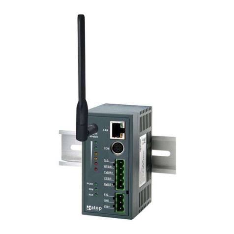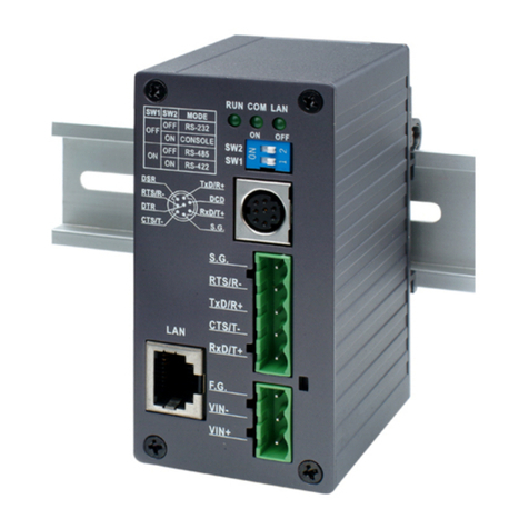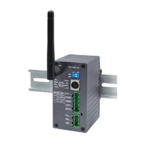
SW5501 –SW5502
Wireless Serial Server
Figure 4.28 Basic Settings for Wireless Connection when Wireless Profile is Disabled........................................39
Figure 4.29 Results of network scanning when uses “scan network” buttons........................................................41
Figure 4.30 Result when there is no wireless network available in the area..........................................................41
Figure 4.31 Wireless Advanced Settings Page when Wireless Profile is Disabled and Topology is set to
infrastucture..............................................................................................................................................................42
Figure 4.32 Wireless Advanced Settings Page when Wireless Profile is Enabled................................................43
Figure 4.33 COM 1 Port Setting Page ...................................................................................................................44
Figure 4.34 Serial Settings Part of COM Port........................................................................................................45
Figure 4.35 Advanced COM Port Settings Page ...................................................................................................46
Figure 4.36 SNMP/Alert Settings Page..................................................................................................................49
Figure 4.37 E-mail Settings Page ..........................................................................................................................51
Figure 4.38 Sending Test E-mail Failed ..................................................................................................................51
Figure 4.39 System Log Settings Page..................................................................................................................52
Figure 4.40 COM Log Settings Page.....................................................................................................................53
Figure 4.41 Event Log Page ..................................................................................................................................54
Figure 4.42 COM Datalog Page.............................................................................................................................55
Figure 4.43 Date/Time Settings Page....................................................................................................................56
Figure 4.44 Admin Settings Page ..........................................................................................................................57
Figure 4.45 Firmware Upgrade Page.....................................................................................................................58
Figure 4.46 Backup/Restore Setting Page.............................................................................................................59
Figure 4.47 Management List Page.......................................................................................................................59
Figure 4.48 Successful Ping with No Packet Loss.................................................................................................60
Figure 4.49 Unsuccessful Ping with 100% Packet Loss........................................................................................60
Figure 4.50 Reboot Page.......................................................................................................................................61
Figure 4.51 Pop-up Windows while Rebooting SW550X with Reloading Countdown in Seconds .........................61
Figure 5.1 Link Mode Options for COM 1 Port.......................................................................................................62
Figure 5.2 An Example of TCP Server Link Mode.................................................................................................62
Figure 5.3 Connection Settings for TCP Server Link Mode...................................................................................63
Figure 5.4 TCP Server Link Mode Settings under COM 1 Page ...........................................................................64
Figure 5.5 An Example of TCP Client Link Mode ..................................................................................................66
Figure 5.6 Connection Settings for TCP Client Link Mode ....................................................................................66
Figure 5.7 TCP Client Link Mode Settings under COM 1 Page.............................................................................67
Figure 5.8 An Example of UDP Link Mode ............................................................................................................68
Figure 5.9 Connection Setting for UDP Link Mode................................................................................................69
Figure 5.10 UDP Link Mode Settings under COM 1 Page.....................................................................................69
Figure 5.11 Virtual COM Application in TCP Server Link Mode ............................................................................71
Figure 5.12 Virtual COM Application in TCP Client Link Mode..............................................................................72
Figure 5.13 Pair Connection Master Application in TCP Server Link Mode.........................................................73
Figure 5.14 Pair Connection Slave Application in TCP Client Link Mode.............................................................74
Figure 5.15 Reverse Telnet Application in TCP Server Link Mode ......................................................................75
Figure 5.16 An Example of Network Topology for Multi-Point Pair Connection in UDP Link Mode.....................76
Figure 5.17 Setting of Multiple TCP Connection Application via Maximum Connection Option...........................77
Figure 5.18 An Example of Network Topology for Multi-Point Pair Connection in TCP Link Mode......................78
Figure 5.19 Wireless Ad-Hoc Peer Settings for SW550X....................................................................................79
Figure 5.20 Wireless Client with WPA2-PSK Security Settings for SW550X......................................................81
Figure 5.21 Wireless Client with PEAP Security Settings for SW550X ...............................................................83
Figure 6.1 Enabled Virtual COM Application in TCP Server Link Mode.................................................................84
Figure 6.2 Enabled Virtual COM Application in TCP Client Link Mode..................................................................84
Figure 6.3 An Example Diagram of Virtual COM Application over TCP/IP Network ...........................................85
Figure 6.4 Enable Virtual COM Application for COM 2 in TCP Server Link Mode ..............................................87
Figure 6.5 Serial/IP Tray Icon on Windows Notification Area ...............................................................................88
Figure 6.6 A Pop-up Window for Selecting Virtual COM Ports...........................................................................88
Figure 6.7 Serial/IP Control Panel Window ...........................................................................................................89
Figure 6.8 Configuring Virtual COM 2 Port as TCP Client...................................................................................90
Figure 6.9 Configuration Wizard Window for COM 1...........................................................................................91
Figure 6.10 Timeout Warning on VCOM Connection ..........................................................................................92
