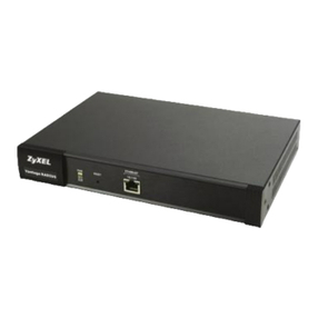
SE59XX Industrial Device Server
Series
Figure 2.1 An Application of SE59XX Industrial Serial Device Server with Multiple Devices .................................... 10
Figure 4.1 List of Device in Device Management Utility............................................................................................... 17
Figure 4.2 Pull-down Menu of Configuration and Network.......................................................................................... 18
Figure 4.3 Pop-up Window of Network Setting ............................................................................................................ 18
Figure 4.4 Authorization for Change of Network Settings........................................................................................... 18
Figure 4.5 Pop-up Notification Window after Authorization ....................................................................................... 19
Figure 4.6 Pop-up Notification Window when there is the same IP address in the network..................................... 19
Figure 4.7 Authentication Required for Accessing Web Interface .............................................................................. 20
Figure 4.8 Warning Pop-up Window for Changing or Resetting Password from Default Value................................ 20
Figure 4.9 Overview Web Page of SE59XX Industrial Serial Device Server. ............................................................... 21
Figure 4.10 Map of Configuring Web Page on SE59XX Industrial Serial Device Server ............................................ 21
Figure 4.11 Overview Web Page.................................................................................................................................... 22
Figure 4.12 Network Settings Web Page ...................................................................................................................... 24
Figure 4.13 Serial Menu ................................................................................................................................................. 25
Figure 4.14 COM 1 Port Settings Web Page................................................................................................................. 26
Figure 4.15 Serial Settings Part of COM 1 Port ............................................................................................................ 27
Figure 4.16 Serial Settings for COM 1 of SE5901B (Note that it supports only RS-232 and RS-485)....................... 28
Figure 4.17 COM 1 Advanced Settings Web Page ....................................................................................................... 29
Figure 4.18 An example of Host-to-Host Connection ................................................................................................. 32
Figure 4.19 Roadwarrior Application using Host-to-Subnet Connection ................................................................... 33
Figure 4.20 Gateway Application using Host-to-Subnet Connection......................................................................... 33
Figure 4.21 An example of network application using a subnet-to-subnet connection via the SE59XX and a peer
device.............................................................................................................................................................................. 33
Figure 4.22 An example of host-network application via the subnet-to-subnet connection.................................... 34
Figure 4.23 An example of host-host application via the subnet-to-subnet connection.......................................... 34
Figure 4.24 IPsec Tunnels Web Page under IPsec Setting Menu ............................................................................... 35
Figure 4.25 IPsec VPN Tunnel with Host-to-Host Topology........................................................................................ 42
Figure 4.26 General Settings for Host-to-Host with Static Peer.................................................................................. 43
Figure 4.27 General Settings for Host-to-Host with Dynamic Peer............................................................................. 43
Figure 4.28 IPsec VPN Tunnel with Host-to-Network Topology ................................................................................. 44
Figure 4.29 General Settings for Host-to-Network with Static Peer............................................................................ 44
Figure 4.30 General Settings for Host-to-Network with Dynamic Peer....................................................................... 45
Figure 4.31 SNMP/Alert Settings Web Page ................................................................................................................ 46
Figure 4.32 E-mail Setting Web Page ........................................................................................................................... 48
Figure 4.33 Log Settings Menu ..................................................................................................................................... 49
Figure 4.34 Log Settings Web Page under Log Settings ............................................................................................. 49
Figure 4.35 COM Log Settings Web Page under System Setup .................................................................................. 50
Figure 4.36 System Log Web Page under System Setup............................................................................................. 51
Figure 4.37 COM Datalog Web Page under Log Settings ............................................................................................ 52
Figure 4.38 System Setup Menu ................................................................................................................................... 52
Figure 4.39 Date/Time Settings Web Page under System Setup ................................................................................ 53
Figure 4.40 Admin Settings Web Page under System Setup....................................................................................... 54
Figure 4.41 Firmware Upgrade Web Page under System Setup ................................................................................. 55
Figure 4.42 Backup/Restore Settings Web Page under System Setup....................................................................... 56
Figure 4.43 Ping Web Page under System Setup ......................................................................................................... 57
Figure 4.44 Unreachable Ping Example ........................................................................................................................ 57
Figure 4.45 Reboot Web Page ....................................................................................................................................... 59
Figure 5.1 Link Mode Options for COM1 Port .............................................................................................................. 60
Figure 5.2 SE59XX is set as a TCP Server Link Mode.................................................................................................. 61
Figure 5.3 Connection Settings for TCP Server Link Mode ........................................................................................ 61
Figure 5.4 TCP Server Link Mode Settings under COM 1 Page................................................................................... 62
Figure 5.5 Example of SE59XX Configured as TCP Client Link Mode ........................................................................ 64
Figure 5.6 Connection Settings for TCP Client Link Mode .......................................................................................... 64
Figure 5.7 Setting in TCP Client Link Mode .................................................................................................................. 65
