Functions and Controls
1
6
12
13
23
7
4
910
11
5
8
Functions and Controls
1
5
6
7
4
2
3
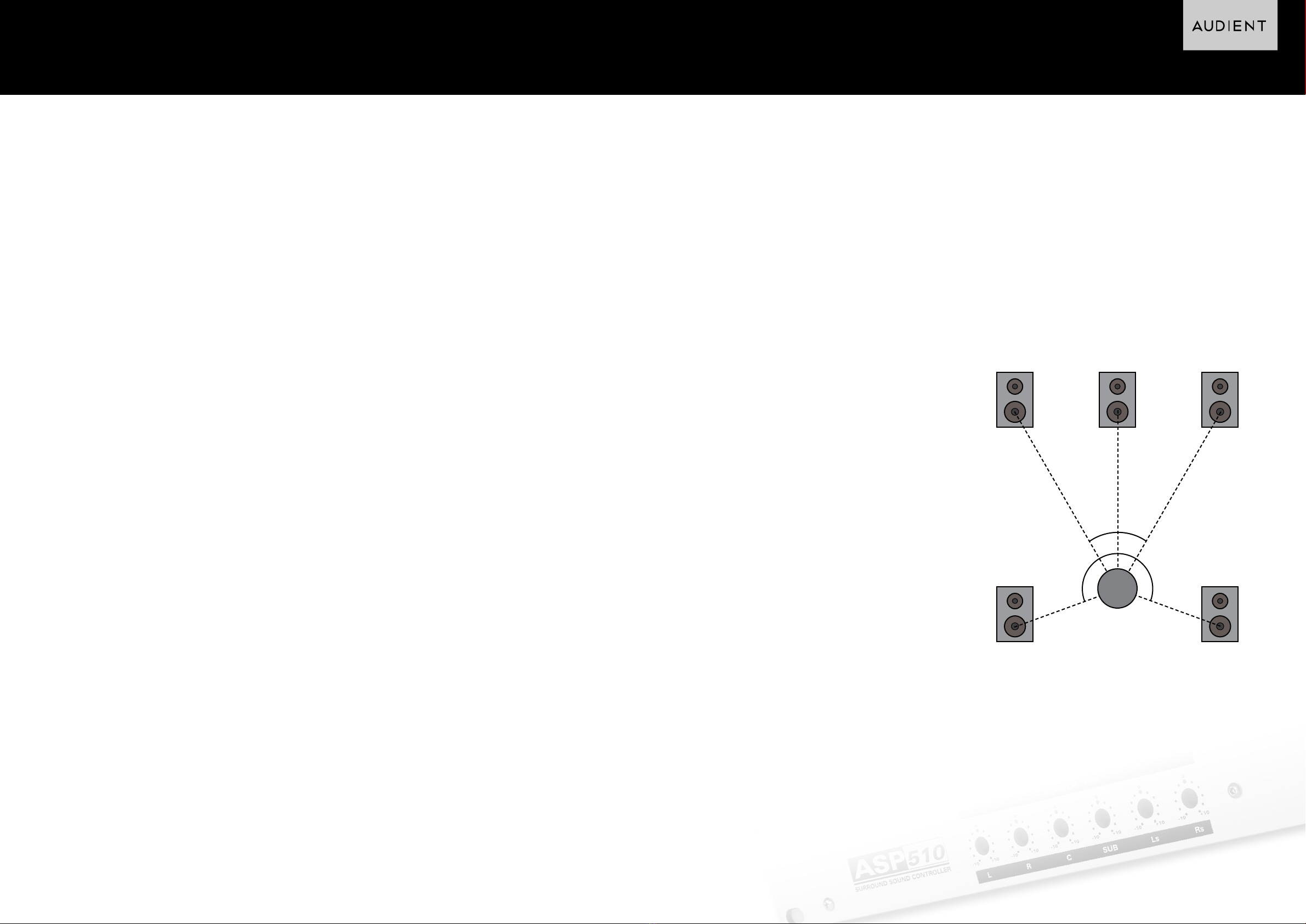
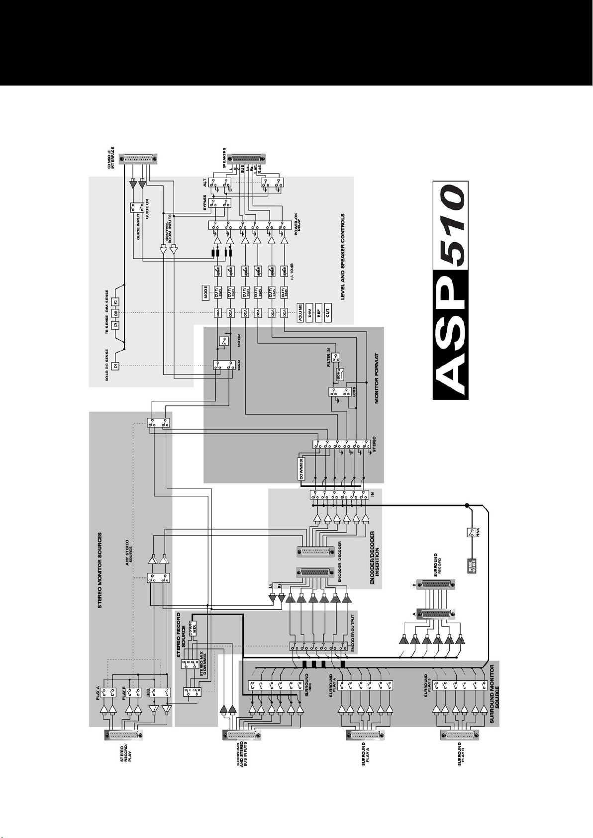
The ASP510 enables the user to select
any one of 5 primary monitor formats:
5.1, LCRS, Stereo, Mono or Bypass.
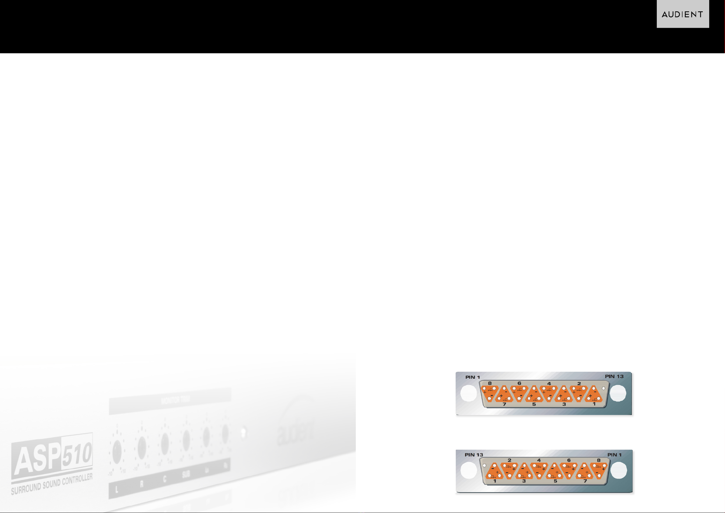
A switchable 120Hz filter is provided for
the sub- bass monitor path (see page
12).
A 5.1FILM mode is also implemented
with the Left surround and Right
surround monitor channels attenuated
by 3dB.
Switching for alternate Left and Right
speakers is provided along with a Bypass
mode enabling monitoring direct from
the mixing console or DAW.
If the logic sense ports have been
connected to the host mixing console
the ASP510 will automatically detect and
action console Solo, Dim and talkback
commands.
The main Volume control operates via
high precision Digital Attenuators to
adjust the level of all speaker outputs.
Cut and Dim controls are also provided
with the Dim level being user settable.
The monitors may also be set to a user
predetermined reference level using the
REF switch - the volume control is then
bypassed.
Each of the six speaker outputs has an
individual twin mode illuminated switch.
These can be set to operate either as
Isolate or Cut switches by using the
associated mode switch.
To make system setup straight forward
the ASP510 has a built in Pink Noise
generator.
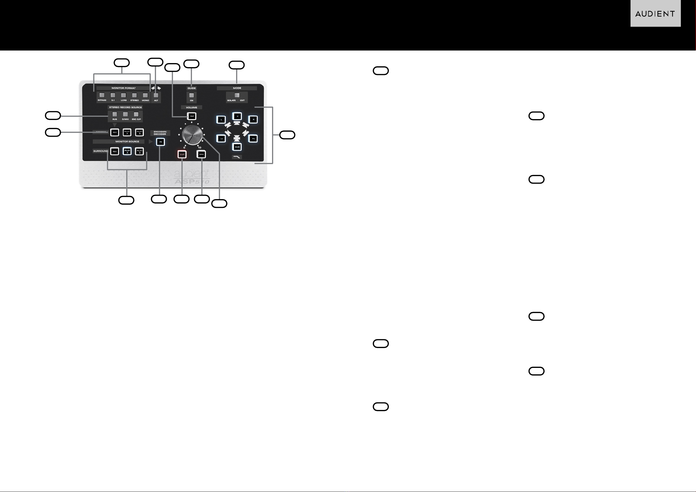
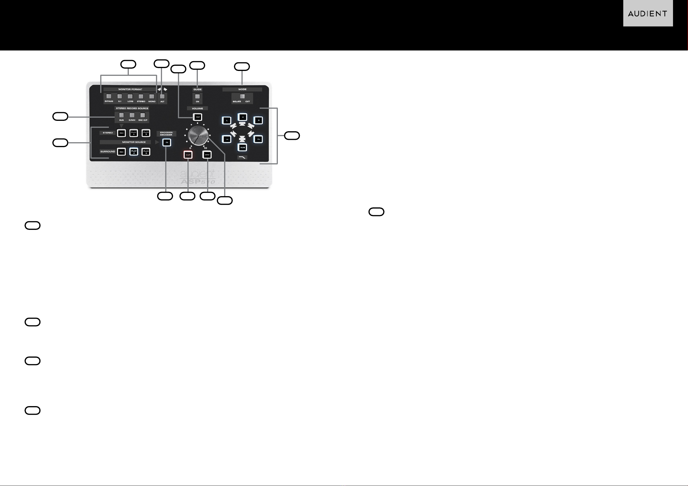
Monitor Level Trim Controls
MONITOR FORMAT is selected using
these five switches. An illuminated legend
displays the selected choice from 5.1,
LCRS, Stereo, Mono and Bypass. All of these
format selection buttons are interlocked
to automatically cancel the previous
selection except Bypass which operates
independently.
To set the 5.1 format to FILM mode hold
down the 5.1 button until it flashes and then
release. To cancel this mode hold down the
5.1 button until it stops flashing.
Bypass sets the entire ASP510 into stereo
mode connecting the console control
room outputs directly to the Left and Right
speakers.
Bypass disables all ASP510 functions other
than the Alternate speaker switching (see
below).To exit from Bypass mode push the
button again.
To restore factory default settings hold
down the Bypass button until it flashes and
then release it.
Alt Monitor Switch
ALT switches the main Left and Right
speaker outputs from the main monitors
to the Alternate (usually small near-field)
monitors.
Ref Button
The Reference button sets all monitor
levels to a user-definable reference level
independent of the volume control setting.
To set the Reference Level hold down the
REF button until it flashes, release it, set
the required level using the main Volume
Control and then push REF again to store
the setting.
Guide
Pressing this button allows a guide track
to be input directly to the main Left and
Right monitors. An associated ON legend is
illuminated when the Guide input is active.
Mode
MODE sets the six illuminated speaker
switches to act in either ISOLATE or CUT
mode.
An illuminated legend shows which mode is
active. The 120Hz low pass filter in the sub-
woofer path is activated by holding down
the illuminated SUB speaker switch until the
filter legend illuminates.
To bypass the filter push again until the
legend is extinguished.
Monitor Switches
Allows the individual outputs to be isolated
or cut depending on the mode selected
using the Mode button above.
Volume Control
Allows to control the output level to all the
monitors.