List of Figures
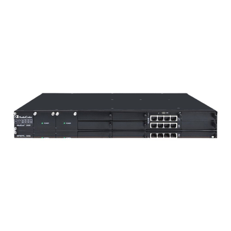
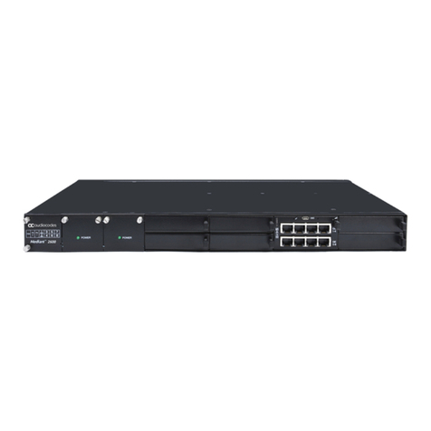
Figure 3-1: Front Panel..........................................................................................................................13
Figure 3-2: SBC Module Ports...............................................................................................................15
Figure 3-3: SBC Module LEDs ..............................................................................................................16
Figure 3-5: Rear Panel...........................................................................................................................18
Figure 4-1: Rubber Feet Locations........................................................................................................20
Figure 4-2: Rear-Mounting Brackets Attached to Rear-Rack Posts (60 cm).........................................23
Figure 4-3: Rear-Mounting Brackets Attached to Rear-Rack Posts (80 cm).........................................23
Figure 4-4: Attaching Rear-Mounting Flange to Chassis' Rear-Side Mounting Holes (60 cm).............24
Figure 4-5: Attaching Rear-Mounting Flange to Chassis' Rear-Side Mounting Holes (80 cm).............24
Figure 4-6: Sliding the Rear-Mounting Flanges into the Rear-Mounting Brackets (60 cm)...................25
Figure 4-7: Sliding the Rear-Mounting Flanges into the Rear-Mounting Brackets (80 cm)...................25
Figure 4-8: Fastening Rear-Mounting Flange to Rear-Mounting Bracket (60 cm)................................26
Figure 4-9: Fastening Rear-Mounting Flange to Rear-Mounting Bracket (80 cm)................................26
Figure 4-10: Front-Mounting Brackets Flush and Aligned with Front-Rack Posts (60 cm)...................26
Figure 4-11: Front-Mounting Brackets Flush and Aligned with Front-Rack Posts (80 cm)...................27
Figure 5-1: Grounding the Device..........................................................................................................28
Figure 5-2: Connecting the LAN Interface.............................................................................................29
Figure 5-3: Ethernet Port Pairs..............................................................................................................30
Figure 5-4: Cabling for 1+1 Ethernet-Port Redundancy (Example).......................................................30
Figure 5-5: Cabling for High Availability (Example)...............................................................................31
Figure 5-6: Serial Interface Cable Adapter and Connector Pinouts ......................................................32
Figure 5-7: Connecting the Serial Interface...........................................................................................32
Figure 5-8: Connecting to Power...........................................................................................................34
Figure 6-1: Connecting ESD Wrist Strap to Chassis ESD Lug..............................................................37
Figure 6-2: Module Handle Partially Pulled Out (Top View)..................................................................37
Figure 6-3: Module Handle Pushed In (Top View) ................................................................................38
List of Tables
Table 3-1: Physical Dimensions ............................................................................................................13
Table 3-2: Front-Panel Description........................................................................................................14
Table 3-3: Power Supply Module LED Description ...............................................................................15
Table 3-4: SBC Module Ports Description.............................................................................................16
Table 3-5: SBC Module LEDs Description.............................................................................................16
Table 3-7: Rear-Panel Description ........................................................................................................18
Table 5-1: RJ-45 Connector Pinouts .....................................................................................................29
Table 5-2: Power Specifications ............................................................................................................33


