•
• Transmission coupler
• Spatter protection cover
•
Connections
•
•
•
LOAD
LOAD
Brown
Blue
•
•
•
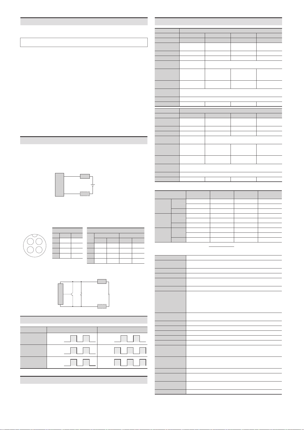
2
3
1
4
Pin Color Func.
- -
- -
Blue 0 V
+V
IEC standards
Pin Normally close
Color Func. Color Func.
+V +V
- - Blue 0 V
- - - -
Blue 0 V - -
Inner circuit
CIRCUIT
LOAD
LOAD
PRD T- -
A: Spatter-resistant type
CM: Connector type
L: Long
O: Normally open
C: Normally closed
V: Oil resistant
IV: Oil resistant
Normally closed
Presence Presence
Nothing Nothing
Load Operation Operation
Return Return
indicator (red)
ON ON
OFF OFF
2 to 100 mA
01)
Protection circuit
polarity protection
Insulation resistance
Vibration
Shock
Ambient humidity
Protection structure
Connection
02)
M12 connector
Material
Spatter-resistant
Installation
General
-
side
2 mm 4 mm 7 mm
Hysteresis
distance
Standard
iron
frequency 01)
Indicator
Installation
General
side
4 mm 14 mm
Hysteresis
distance
Standard
iron
frequency 01)
Indicator
01) Ø 12 mm Ø 30 mm
Cable Normal
-
-
Cable
connector
Normal
-
- - -
Connector Normal
-
- -
Spatter-resistant type
order


