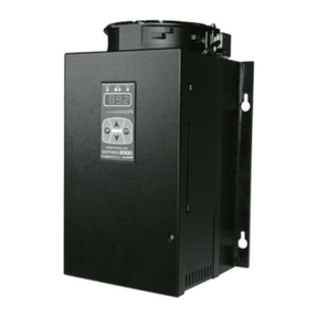
1 Product Introduction
10 © Copyright Reserved Autonics Co., Ltd.
6.2.2 MV High/Low-limit value settings [PAR2 →H-MV / L-MV] ......................... 66
6.2.3 Ramp settings [PAR2 →RAMU/ RAMD/ rUNT] ............................................ 67
6.2.4 Auto/Manual control settings ...................................................................... 69
6.2.5 Output settings ........................................................................................... 72
6.3 Temperature control ................................................................................................ 73
6.3.1 Temperature control mode [PAR3 →C-MD] ............................................... 73
6.3.2 ON/OFF control [PAR3 →C-MD →ONOF] .................................................. 74
6.3.3 PID control [PAR3 →C-MD →PID] ............................................................ 75
6.3.4 Auto-tuning ................................................................................................. 77
6.4 Alarm output ............................................................................................................ 79
6.4.1 Alarm operation [PAR4 →AL-1/AL-2/AL-3]............................................ 79
6.4.2 Alarm output options [PAR4 →AL!T/AL@T] .............................................. 81
6.4.3 Alarm SV settings [PAR1 →AL!L/AL!H/AL@L/AL@H/AL#L/AL#H].......... 82
6.4.4 Alarm output hysteresis [PAR4 →A!HY/A@HY/A#HY] ............................... 82
6.4.5 Alarm N.O./N.C. [PAR4 →A!N/A@N/A#N].................................................. 83
6.4.6 Alarm output delay settings
[PAR4 →A!ON / A!OF/ A@ON / A@OF/ A#ON / A#OF].................................. 84
6.4.7 Loop break alarm(LBA) [PAR4 →AL-1/AL-2/AL-3 →LBA] .................... 85
6.4.8 Sensor break alarm [PAR4 →AL-1/AL-2/AL-3 →SBA] .......................... 87
6.4.9 Heater burnout alarm [PAR4 →AL-1/AL-2/AL-3 →HBA] ....................... 88
6.4.10 Alarm output deactivation [PAR5 →DI-K→AlRE] .................................... 89
6.4.11 Alarm output examples............................................................................... 90
6.5 Analog transmission ................................................................................................ 93
6.5.1 Analog transmission output value settings [PAR4 →AoM1/AoM2]............ 93
6.5.2 Transmission output high/low-limit value settings
[PAR4 →FsL1/FsH1→FsL2/FsH2].......................................................... 93
6.6 Communication settings .......................................................................................... 95
6.6.1 Unit address settings [PAR4 →ADRS]........................................................ 95
6.6.2 BPS (bits per second) settings [PAR4 →BPS] ........................................... 95
6.6.3 Communication parity bit [PAR4 →PRTY].................................................. 96
6.6.4 Communication stop bit settings [PAR4 →STP]......................................... 96
6.6.5 Response wait time settings [PAR4→RSwT].............................................. 96
6.6.6 Enable/Disable communication write[PAR4→COMW] ................................. 97
6.6.7 USB to Serial communication connection .................................................. 97
6.7 Additional features................................................................................................... 98
6.7.1 Monitoring................................................................................................... 98
6.7.2 RUN/STOP [PAR1 →R-S] ......................................................................... 99
6.7.3 Multi SV .................................................................................................... 100
6.7.4 Digital input............................................................................................... 101
6.7.5 Error.......................................................................................................... 103
6.7.6 User level setting [PAR5 →USER]............................................................ 104
6.7.7 Lock settings ............................................................................................ 104
6.7.8 Parameter reset [INIT] ........................................................................... 105
6.7.9 Password settings [PAR5 →PWD]............................................................. 105
7Setting group parameter description ....................................................107
7.1 Setting group [ SV ] ............................................................................................... 107
7.2 MV monitoring/manual control setting group [ MV ] ............................................... 107
7.3 Parameter 1 setting group [ PAR1 ]....................................................................... 108
